Well UPS-HEATST-COMMANDER Series User manual

Operation Manual
UPS-HEATST-COMMANDER300-1600W-WL
UPS-HEATST-SPRINTEN300-600W-WL
UPS-HEATST-EVOLUTION1000W-WL

~ - 1 -~
Table of Contents
1 Safety Information .................................................................................- 0 -
2 Product Overview ...............................................................................- 1 -
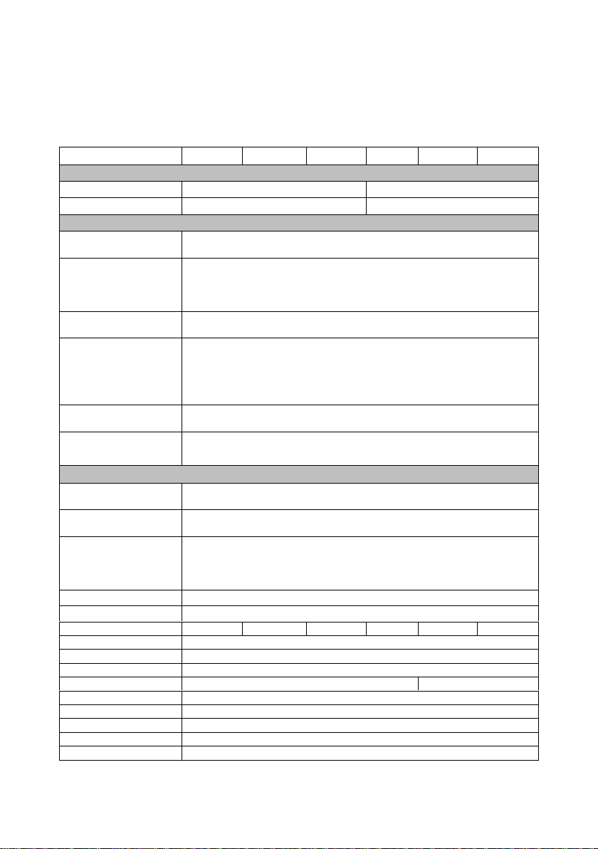
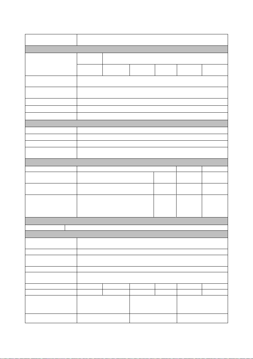
2.1 Specifications................................................................................- 1 -
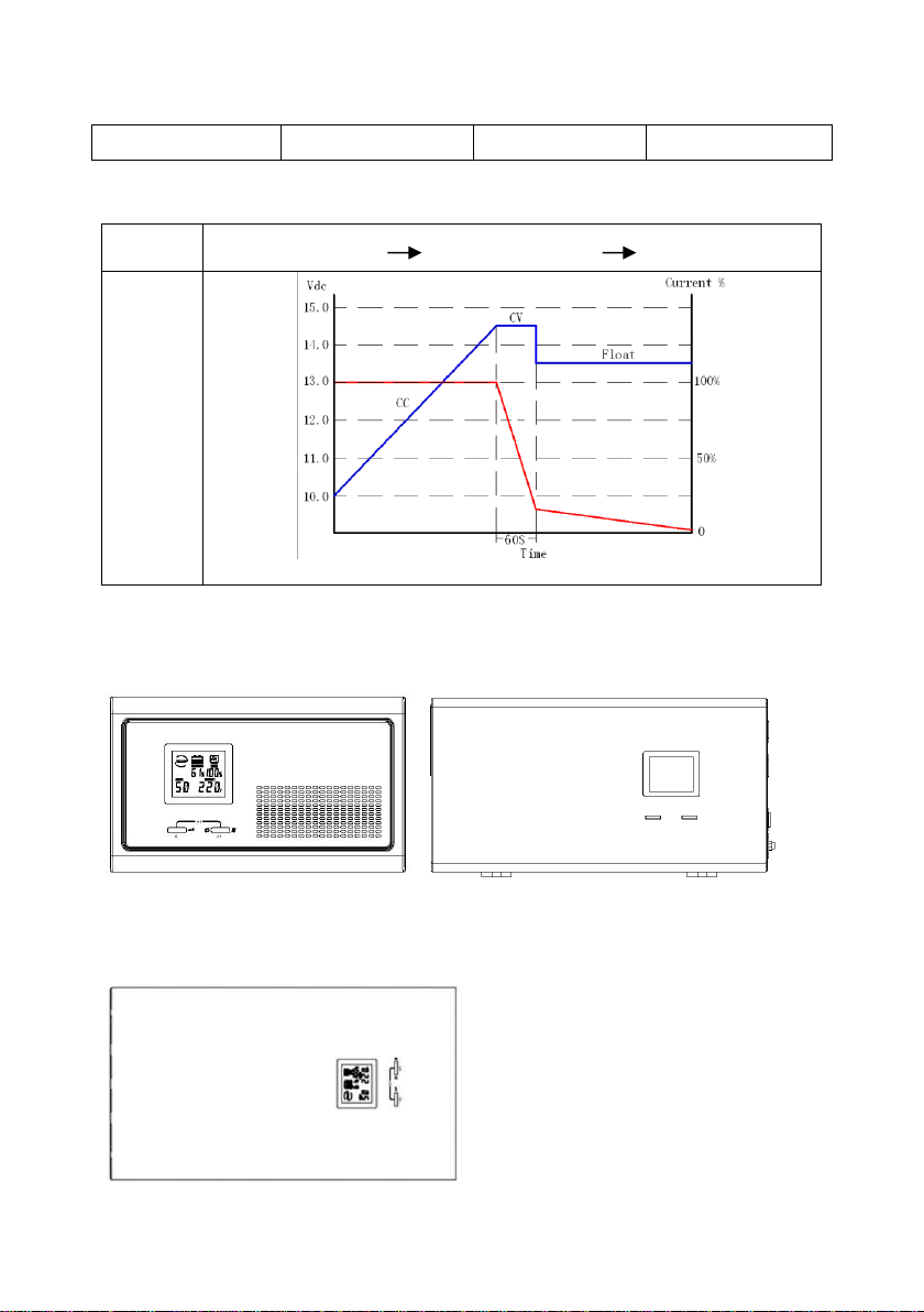
2.2 Front panel features......................................................................- 3 -
2.3 Rear panel features.......................................................................- 4 -
3 Installation Instructions......................................................................- 5 -
3.1 Unpacking inspection ....................................................................- 5 -
3.2 Installation ....................................................................................- 5 -
4 Operations ..........................................................................................- 7 -
4.1 Turn the inverter On / Off...............................................................- 7 -
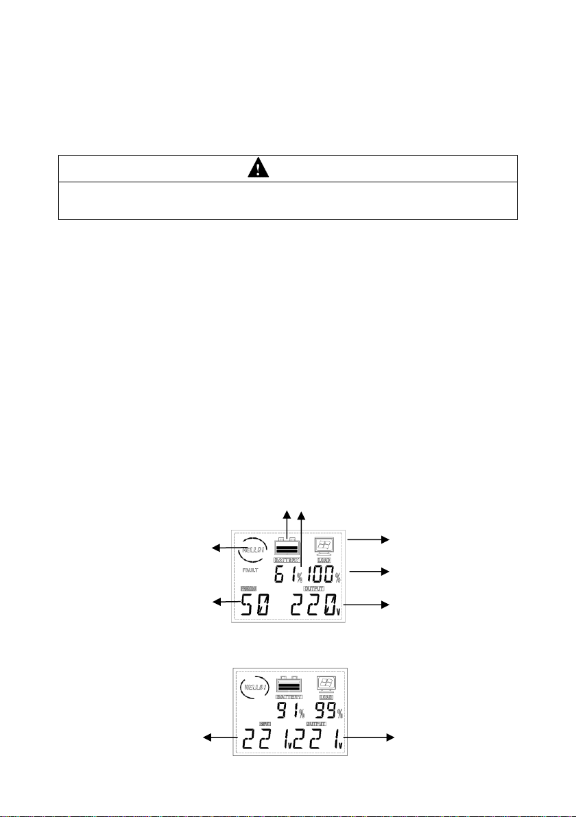
4.2 Display interface ...........................................................................- 7 -
4.3 MPPT & DC modules (Optional) status indicators...........................- 8 -
4.4 Settings ........................................................................................- 8 -
5 Troubleshooting................................................................................ - 11 -

Thank you for choosing WELL. Please read carefully the following
instructions and keep them within reach.
1 Safety Information
CAUTION
Non-qualified electricians are forbidden to open the case due to hazard of
electrical shock.
Consulting the dealer is required before using for below equipment. Its application,
configuration, management and maintenance must be specially considered and designed.
Not recommended for below special applications.
Medical equipment which is directly related to patients’life
Elevator and other equipment which may endanger personal safety
Apply to traffic system
Apply to nuclear, power system
Apply to aviation and aerospace
Other special usages.
Safety and General Information
Read all safety information and operating instructions carefully before attempting
to install, operate, service or maintain the inverter.
Do not disassemble this inverter. Contact your local service center if maintenance
or repair is needed.
Disconnect all connection wiring before maintenance or cleaning to avoid the risk
of electric shock.
Do not use liquid extinguisher if there is a fire, a dry powder extinguisher is
recommended.
Do not dispose of the batteries with fire. The batteries may explode.
Do notopen or mutilatebatteries.Released electrolyte inside is harmful to theskin
and eyes, and maybe toxic.
Do not connect the positive pole and negative pole directly, otherwise it will cause

~ - 1 - ~
electric shocks or will be on fire.
2 Product Overview
2.1 Specifications
MODEL
300 W
600 W
1000 W
1600 W
2500 W
3500 W
DC Input (the inverter must be connected to batteries to work properly)
Nominal input voltage
12 V
24 V
DC input range
10 ~ 15 V
20 ~ 30 V
AC Input
Bypass input range
0 ~ 264 Vac for 220 Vac / 230 Vac / 240 Vac,
0 ~ 132 Vac for 100 Vac / 110 Vac / 115 Vac / 120 Vac
Mains input range
150 ~ 282 Vac for 220 Vac; 156 ~ 294 Vac for 230 Vac;
163 ~ 307 Vac for 240 Vac; 68 ~ 128 Vac for 100 Vac;
75 ~ 141 Vac for 110 Vac; 79 ~ 148 Vac for 115 Vac;
82 ~ 154 Vac for 120 Vac.
Input frequency range
50 Hz / 60 Hz (Auto-sense & Settable: 5% ~ 15%,default 15%),
42.5 ~ 57.5 Hz for 50 Hz, 51 ~ 69 Hz for 60 Hz
Input range of the
generator
99 ~ 282 Vac for 220 Vac; 104 ~ 294 Vac for 230 Vac;
108 ~ 307 Vac for 240 Vac; 45 ~ 128 Vac for 100 Vac;
50 ~ 141 Vac for 110 Vac; 52 ~ 148 Vac for 115 Vac;
54 ~ 154 Vac for 120 Vac. No AVR in
generator mode
Input frequency range
of the generator
40 ~ 70 Hz
Input power matching
of the generator
Rated power 10% ~ 150%,
regulating step 10%,default 120%
Output
Inverter output range
220 Vac / 230 Vac / 240 Vac ± 5% or
100 Vac / 110 Vac / 115 Vac / 120 Vac ± 5% (settable)
Bypass output range
0 ~ 264 Vac for 220 V / 230 V / 240 V,
0 ~ 132 Vac for 100 V / 110 V / 115 V / 120 V
Mains output range
174 ~ 242 Vac for 220 Vac; 182 ~ 253 Vac for 230 Vac;
190 ~ 264 Vac for 240 Vac; 79 ~ 109 Vac for 100 Vac;
87 ~ 121 Vac for 110 Vac; 93 ~ 125 Vac for 115 Vac;
95 ~ 133 Vac for 120 Vac.
Output frequency
50 Hz / 60 Hz ± 0.3 (Auto-sense & settable)
Output waveform
Pure sine wave
Output power
300 W
600 W
1000 W
1600 W
2500 W
3500 W
Efficiency
Max. 95% (Mains mode); Max. 80% (Inverter mode)
ECO mode
Settable, load < 3%,enter in 80 s
No-load shutdown
Settable, time can be set (1 ~ 99 min), load can be set (3% ~ 50%)
Transfer time
≤ 10 ms
≤ 15 ms
Power factor
1.0
THDV
< 5% (linear load)
Inductive load
Yes
Motor load
Yes
Rectifier load
Yes

~ - 2 - ~
Overload capability
Mains mode: 110% 120 s; 125% 60 s; 150% 10 s (switch to bypass)
Inverter mode: 110% 60 s; 125% 10 s; 150% 10 s (shut down)
Battery
Charging current
(selectable)
Default
10 A
Default 20 A, regulating step 1 A (< 10 A) / 5 A (> 10 A)
Max. 15 A
Max. 30
A
Max. 40 A
Max.
40 A
Max. 50
A
Max. 60 A
Equalizing charge
voltage
Single battery 14.4 Vdc (default), 13.6 ~ 15 Vdc settable
Floating charge
voltage
Single battery 13.7 Vdc (default), 13.2 ~ 14.6 Vdc settable
DOD
Single battery 10.8 Vdc (default), 9.6 ~ 13 Vdc settable
EOD
Single battery 10.2 Vdc (default), 9.6 ~ 11.5 Vdc settable
Reverse warning
Buzzer
Alarm
Switch on / off
Continuous beep 2 s
Low battery
Beep 0.2 s at interval of 0.4 s
Overload
Beep 2 s at interval of 2.5 s
Mains power
abnormal
Beep 0.3 s at interval of 5 s
MPPT Modules (Optional)
Model
10 A / 20 A / 30 A / 40 A
/
/
Max. PV input voltage
(Voc)
40 V
60 V
/
/
PV optimum operating
voltage (Vmp)
18 V ~ 32 V
29 V ~
48 V
/
/
Max.PV power
120 W / 240 W /
360 W / 480 W
240 W /
480 W /
720 W /
960 W
/
/
DC Modules (Optional)
Model
5 V (2 A), 9 V / 12 V (1 A), 15 V / 24 V (1 A), 12 V / 24 V (10 A)
Others
Protections
Overload –short-circuit –overvoltage –undervoltage –overcharge –
overtemperature –excessive low battery –missing insert
Interface
LCD & BUZZER
Operating
temperature
0℃~ 40℃
Operating humidity
Relative humidity ≤ 93%
Altitude
< 1000 m, (above 1000 m, derating 1% for each additional 100 m),
4000 m max.
Net weight (kg)
8.0/8.5/7.4
10.9/11.4/11
14.0/14.6
18.0/18.5
32.0
36.0
Gross weight (kg)
9.0/9.5/8.4
11.9/12.4/12
15.0/15.6
19.0/19.5
34.0
38.0
Dimensions (W×D×H)
mm
280×258×120 (w/o option)
293×280×160 (w/ option)
400×210×127 (Wall
mounted)
293×280×160
302×479×209
Packaged dimensions
330×352×200 (w/o option)
370×355×235 (w/ option)
370×355×235
353×582×287

~ - 3 - ~
(W×D×H) mm
490×290×195 (Wall
mounted)
Note: Specifications are subject to change without notice.
Charging features
Charging
process
Three-stage:
CC (constant current) CV (constant voltage) Float (floating charge)
Process
diagram
Constant voltage charging time: 60 S
2.2 Front panel features
300 W ~ 1600 W front panel
Tower type Wall mounted type
2500 W ~ 3500 W front panel

~ - 4 - ~
2.3 Rear panel features
300 W ~ 1600 W rear panel ①AC input socket
②Output sockets
③Overcurrent protector
④Buzzer for battery reverse
⑤Battery wiring
⑥Battery breaker
⑦Fan
Tower type
Wall mounted type
⑧DC output fuse
⑨MPPT (optional)
⑩DC output (optional)
Optional model (with MPPT / DC modules)
2500 W ~ 3500 W rear panel
① nput/output terminal block
②Overcurrent protector
③Battery breaker
④Buzzer for battery reverse
⑤Battery wring terminal
⑥Fan

~ - 5 - ~
3 Installation Instructions
3.1 Unpacking inspection
Inspect the contents upon receipt. Notify the carrier and dealer if the unit is
damaged.
300 W ~ 1600 W package contents
300 W ~ 1600 W Inverter
AC input power cords
Operation manual
2500 W ~ 3500 W package contents
2500 W ~ 3500 W Inverter
Operation manual
3.2 Installation
CAUTION
The inverter is designed for indoor use. Do not operate this UPS in direct
sunlight, in contact with fluids, or where there is excessive dust or humidity.
Place batteries in sound ventilation environment.
Use insulated tools to reducethe risk of short-circuit when installing or working with
the inverter, the batteries, or other equipments attached to this unit.
Be sure that the ground terminal has been connected with the ground.
3.2.1 Installation information
Inspect whether the battery voltage and Mains voltage are correct or not.
Connect the inverter with batteries, utility power and loads. Be sure all wiring is
correct, terminals are screwed tightly and terminal cover is locked.
Open the battery breaker, press ON button, then the inverter starts up in 3
seconds, and then check if the load has problem (overload, short-circuit ect.). If it

~ - 6 - ~
does, check and correct until confirmingit is normal, and then connect to the utility
power.
3.2.2 Connect external battery
300 W / 600 W / 1000 W inverter battery connection
Optional model (with MPPT modules)
(Notethat thered cableis connected to thepositive terminal, black cable is connected
to the negative terminal)
1600 W inverter battery connection
Optional model (with MPPT modules)
(Notethat thered cableis connected to thepositive terminal, black cable is connected
to the negative terminal)
2500 W / 3500 W inverter battery connection
(Note that the red cable is connected to the positive terminal, black cable is

~ - 7 - ~
connected to the negative terminal, and 2500 W battery cable is more than 35 mm2,
3500 W battery cable is more than 50 mm2)
4 Operations
CAUTION
Turn on the inverter in battery mode first. Be sure that the load has no problem
(overload, short-circuit ect.) before connecting to utility power.
4.1 Turn the inverter On / Off
Without connecting to utility power, press and hold “ON”button for 3 seconds,
release it until the buzzer beeps, the inverter starts up. In the process of the
inverter running, press and hold “OFF”button for 3 seconds, release it until the
buzzer beeps, the inverter is shut down.
When the inverter works in mains power / AC mode, press and hold “OFF”button for 3
seconds, release it until the buzzer beeps, the inverter goes to bypass mode.
When the inverter works in bypass mode, press and hold “ON”button for 3
seconds, release it until the buzzer beeps, the inverter goes to AC mode.
4.2 Display interface
Inverter mode
Mains power mode
Load
Battery capacity
Inverter output voltage
Fan swing
Inverter output frequency
Input voltage
Output voltage
Load

~ - 8 - ~
4.3 MPPT & DC modules (Optional) status indicators
Modules
Status
LED Indicators
Action
MPPT
Module
Normal PV charging
Yellow and green indicators
are lit continuously
Operating is normal
MPPT over-
temperature
Red indicator is lit
continuously
MPPT charging is
turned off
PV low voltage
Green indicator extinguishes
MPPT charging is
turned off
PV high voltage
Green indicator flashes
MPPT charging is
turned off
Battery overvoltage
protection
Yellow indicator flashes
MPPT charging is
turned off
DC
Module
DC module output
overload
Red indicator is lit
continuously
Fuse of DC module
is blown out, and
output is interrupted
4.4 Settings
4.4.1 Setting operation
In normal mode, press and hold “ON”+ “OFF”button at the same time for 3
seconds to go to Setup mode.
In Setupmode, press andhold “ON”+ “OFF”buttonatthesame timefor3 seconds
to exit from Setup mode, and the setting are not saved.
In Setup mode, press “ON”button for page turning to select configuration options.
In Setup mode, press “OFF”button to configure current settings.
In Setup mode, press “ON”button to turn to page “Save & Exit”interface, press
“OFF”button and select “Y”, then press “ON”button to confirm to save datas and
exsit from Setup mode.
After the setting is configured, shut down and restart the inverter before the
settings takes effect.
In normal mode and starting state, press “OFF”button to mute.

~ - 9 - ~
If there is failure and failure is solved, press “OFF”button first and release it to
press “ON”button, and restart the inverter for normal use.
4.4.2 General settings
Configure these settings at any time, using the display interface.
No.
Parameters
Default
Value
Options
LCD Display
1
OUT: Rated output voltage of the
inverter (option)
220V
220V / 230V
/ 240V
2
INP: Input power matching of the
generator (option)
120%
10% ~ 120%
(based on
rated power)
3
HZ: Rated output frequency of the
inverter (option)
50HZ
50HZ / 60HZ
4
RANG: Input frequency range
setting (option)
± 5%
± 5% ~ ±
15%
5
B: Equalizing charge voltage
(option)
14.1V
13.6V ~
15.0V
6
F: Floating charge voltage (option)
13.5V
13.2V~14.6V
7
A: Battery low voltage alarm point
setting (option)
10.8V
9.6V ~ 13.0V
8
E: End of discharge voltage
(option)
10.2V
9.6V ~ 11.5V

~ - 10 - ~
9
CUR: Charging current (option)
10A
(300W )
20A
(600W
~3500W)
0 ~ 60A
10
IECO: Inverter no-load ECO mode
Note: If select “Y”, check whether
the configured load rate in
“Inverter shutdown load rate”is
correct or not, if not, change it.
(option)
N
Y / N
11
INLS: Inverter no-load shutdown
function
Note: If select “Y”, check whether
the configured load rate in
“Inverter shutdown load rate”is
correct or not, if not, change it.
(option)
N
Y / N
12
INLS: Setting of the load rate of
UPS auto-shutdown, The load rate
of shutdown needed on the scene
shall prevail during application.
(Shall be taken as valid only when
DC supply power) (option)
3 %
3 % ~ 50 %
13
INLS: Setting of the delay time of
UPS auto-shutdown, When load ≤
setting value, the system will shut
down after the configured time.
(Shall be taken as valid only in
battery mode) (option)
1 min
1 ~ 99 min
14
ACAU: AC self-starting function
(option)
Y
Y / N
15
DCAU: DC auto restart function
Note: If select “Y”, check whether
the configured time in “DC auto
restart time”is correct or not, if not,
change it. (option)
N
Y / N

~ - 11 - ~
16
T: DC auto restart time (option)
1H
0.5H ~ 8.0H
17
ITR: Input voltage display setting ,
displays the current rated voltage
of the system; If select “100 /…/
240”, the input voltage displays
“100V /…/ 240V”, the transformer
variable is the configured voltage
value: rated voltage value. (option)
OFF
200 - 240V
UPS: OFF /
100 / 110 /
115 / 120;
100 - 120V
UPS: OFF /
200 / 220 /
230 / 240
18
OTR: Output voltage display
setting, displays the current rated
voltage of the system; If select “100
/…/ 240”, the output voltage
displays “100 V/…/240 V”, the
transformer variable is the
configured voltage value: rated
voltage value. (option)
OFF
200 - 240V
UPS: OFF /
100 / 110 /
115 / 120;
100 - 120V
UPS: OFF /
200 / 220 /
230 / 240
19
SAVE: Save and Exit
Y / N
5 Troubleshooting
This section lists the status and alarm messages that the UPS might display. A
suggested corrective action is listed with each display message to help you
troubleshoot problems.
No.
Problem
Description
Display
Message
Corrective Action
1
AC output short
circuit
Check if the load is short circuited.

~ - 12 - ~
2
AC output
voltage is too
high
Contact the dealer or supplier from whom it
was purchased.
3
AC output
voltage is too low
Contact the dealer or supplier from whom it
was purchased.
4
Output overload
Check the load.
5
Relay fault
Contact the dealer or supplier from whom it
was purchased.
6
MOSFET over-
current
Contact the dealer or supplier from whom it
was purchased.
7
MOS
overtemperature
Decrease the operating load. Contact the
dealer or supplier if the problem persists.
8
Connection of
heat sink and
temperature
sensor abnormal
Contact the dealer or supplier from whom it
was purchased.
9
Transformer
overtemperature
Decrease the operating load. Contact the
dealer or supplier if the problem persists.
10
Inverter AC
output voltage is
too high
Contact the dealer or supplier from whom it
was purchased.
11
Inverter AC
output voltage is
too low
Contact the dealer or supplier from whom it
was purchased.

~ - 13 - ~
12
Soft-start fault
Contact the dealer or supplier from whom it
was purchased.
13
BUS voltage is
too high (Battery
is overcharged)
Check the battery voltage. Contact the
dealer or supplier if the problem persists.
14
Charging over-
current
Contact the dealer or supplier from whom it
was purchased.
15
Battery voltage is
too high
Check the battery voltage.
16
Battery over-
discharge
protection
Check the battery voltage
17
Fault self-locking
Wait for auto clearance or manually shut
down and restart the inverter
18
CT fault
Check the CT signal line
For DC module (optional) failure, replace the DC output fuse if the red LED indicator
on the DC module is illuminated.

~ - 14 - ~
Ecological information:
Waste electrical and electronic equipment are a special waste category, collection ,
storage, transport , treatment and recycling are important because they can avoid
environmental pollution and are harmful to health. Submitting waste electrical and
electronic equipment to special collection centers makes the waste to be recycled
properly and protecting the environment. Do not forget ! Each electric appliance that
arrive at the landfill, the field , pollute the environment!
Importer & distributor:
SC VITACOM ELECTRONICS SRL
CIF: RO 214527
Tel. 0264-
438401*
sales@vitacom.ro
www.vitacom.ro

~ - 15 - ~
Manual de utilizare
UPS-HEATST-COMMANDER300-1600W-WL
UPS-HEATST-SPRINTEN300-600W-WL
UPS-HEATST-EVOLUTION1000W-WL

~ - 16 - ~

~ - 17 - ~
Cuprins
1 Informații de siguranță...............................................................- 0 -
2 Prezentarea produsului............................................................- 1 -
2.1 Specificații.............................................................................- 1 -
2.2 Caracteristici ale panoului frontal ........................................- 3 -
2.3 Caracteristici ale panoului posterior ....................................- 4 -
3 Instrucțiuni de montaj..............................................................- 5 -
3.1 Inspecția la despachetare .....................................................- 5 -
3.2 Montaj....................................................................................- 5 -
4 Utilizare.....................................................................................- 7 -
4.1 Pornirea și oprirea invertorului.............................................- 7 -
4.2 Interfața de afișare ................................................................- 7 -
4.3 Indicatori de stare pentru MPPT și modulele DC (opțional) - 8 -
4.4 Reglaje...................................................................................- 8 -
5 Depanare ................................................................................ - 11 -
This manual suits for next models
6
Table of contents
Languages:
Other Well Inverter manuals
Popular Inverter manuals by other brands

BARRON
BARRON EXITRONIX Tucson Micro Series installation instructions

Baumer
Baumer HUBNER TDP 0,2 Series Mounting and operating instructions

electroil
electroil ITTPD11W-RS-BC Operation and Maintenance Handbook

Silicon Solar
Silicon Solar TPS555-1230 instruction manual

Mission Critical
Mission Critical Xantrex Freedom SW-RVC owner's guide

HP
HP 3312A Operating and service manual