welldana 46-100200 User manual

Installation
&
operating instruction.
Welldana® Machine unit with cartridge filter.
Type 46-100200 – Household model.
Welldana A/S reserves the right to make product changes without notice.
Copyright. Welldana A/S
Edition 1.2 03-2002. language: GB.

2
Contents
Standards.......................................... 3
Welldana® Machine unit components.. 3
Electrical data…................................. 3
Filter data…........................................ 3
Pump data, etc ….............................. 3
Conversion time…............................. 3
Technical equipment room layout… 4
Welldana® Machine unit installation… 4
Accompanying manuals…................. 5
Fig. 1. ….............................................. 5
Starting and operating the spa…...... 6
Cleaning & maintenance…................ 7
Safety precautions….......................... 7
Serial number…................................. 7
Electrical control panel.

3
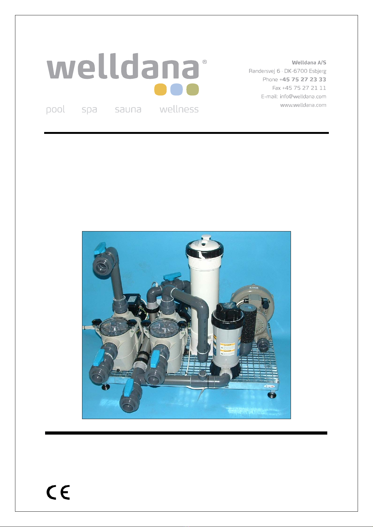
Congratulations on your new Welldana® Machine Unit.
Please read this manual carefully before installing and operating the unit.
On receipt of the unit, please check for transport damage immediately.
Never lift the Machine unit by the pipes or other components. Always lift it by the grid.
This manual is mainly concerned with the Machine unit, although the spa tub will also be mentioned.
For further information on controls, filter, etc, see the accompanying manuals.
Standards.
Welldana® Machine Units comply with current rules and standards on safety.
The product complies with: EN 292-1, EN 294, EN 349, EN 60204-1, EN 50081-2
EN 60 335-2-41, EN 50582-2, EN 55014, MC: EN 50082-1. IP X4.
(Electric heater and 3-function control: EN 60335-2-60: 2000)
The product is CE marked.
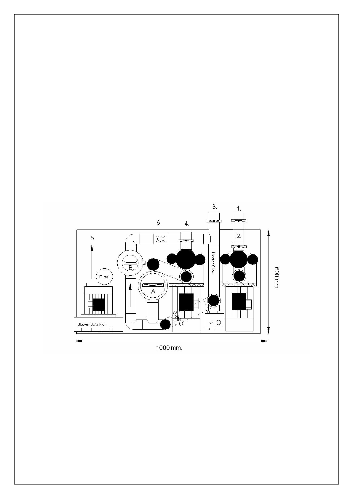
Welldana® Machine Unit incorporates:
1-pcs. 36-202050 Filter pump 2-pcs. 41-700069 Cartridge filters.
1-pcs. 34-110409 Electric heater 1-pcs. 30-001394 Chlorinator
1-pcs. 36-202113 Hydro-jet pump 1-pcs. 34-015040 Tub control panel
1-pcs. 64-112031-1 3-function control
1-pcs. 64-350150 Transformer 1-pcs. 34-140312 Contactor for electric heater
2-pcs. 64-108225 Level sensor 1-pcs. 66-112075 Regenerative fan
1-pcs. 34-190120 Pressure switch 1-pcs. 34-015041 Remote control unit for
temperature regulation and digital temperature display.
1-pcs. assembly steel grid 600•800 mm
Electrical data.
Power cable 1 4 G 1,5 mm² PKAJ cable; 2 • 230 N + earth.
Power cable 2 4 G 1,5mm² PKAJ cable; 3 • 400 + earth. (electric heater)
Total wattage 12 kW (including 9 kW electric heater)
Voltage 3 • 400 V AC 50-60 Hz
Fuse group 16 A 3-phase group switch (2-pcs)
Filter data.
Filter 6,9 m². Cartridge filter
Filter flow Max 21 m³/hour.
Filter part. Spare part cartridge, type 48-709068.
Pump data, etc.
Filter pump 0.55 kW; 230 V; IP 54; 3,5 A; nominal 13,5 m³ at 8 m
Hydro-jet pump 1.10 kW; 230 V; IP 54; 7.0 A; nominal 23 m³ at 8 m
Regenerative fan 0.75 kW; 230 V; IP 54; 5.8 A
Transformer - lighting 230/12 V AC; 60 VA IP 25
Kontakterboks. 3-poled; coil voltage (A1-A2) 230 V; load 20 A AC3
Klorinator. Inline with controls; uses slowly dissolving chlorine tablets
Conversion time.
The machine unit is suitable for use with the following spa tubs or similar.
The quantity of water in the spa tub should not exceed 1100 litres.
Conversion time for 1100 litre spa to above machine unit = 0.12 hours.
26-221840 Octave. 26-222040 Classic. 26-221800 Victoria.
26-221370 Catalina. 26-221855 Janette.

4
Technical equipment room layout.
Overall, the desired location of the machine unit plus filter and the spa tub, the relative heights of the
two units and the distance between them must be decided.
A. The technical equipment room must have a drain of sufficient capacity.
B. The technical equipment room should be concrete floored.
C. The technical equipment room must be equipped with two 16 A 3-phased principal groups.
D. The technical equipment room must have a cold water tap and stop cock. ¾ ".
E. The technical equipment room must have a ventilation shaft.
F. The technical equipment room must have a floor area of at least 1.36 m² (1.70 • 0.80 m).
G. The technical equipment room should have at least 1.80 m to the ceiling.
Important. As installation requires the connection of water and electricity, this work must only be
performed by an authorised plumber/authorised electrician.
Image® Machine Unit installation.
Overall, the desired location of the Machine unit and filter must be decided.
Important: An air loop must be inserted between fan/blower and the spa tub. The air loop must be at
least 30 cm above tub water level.
A ball valve for emptying the tub must be installed between spa tub and air loop.
Ball valve not provided.
Mount electrical panel on wall. Position electrical panel to the left of Machine unit. Mount electrical
panel with 150 cm from floor to upper edge of panel. Use screws and plugs provided.
Install 3-function touch pad and two level sensors. One of the sensors is a safety sensor for the 3-
function panel. The other is a level sensor for the tub control panel level control. See fig. 2.
Run power cables 1 and 2 to main switch. The Machine unit must be connected to an electricity
supply with high-sensitivity earth fault current breaker. The Machine unit is equipped with screw
(located on the side of the grid) for potential equalisation connection.
Install ¾" filling valve on filter pump outlet (tee-piece with ¾" thread). The required cable is pre-
attached. Filling valve not provided. For some OEM customer is the valve and filter mounted. The
valve has a ½” thread connection.
Important.
The pressure switch may require adjustment in order to prevent the water level in the tub from
activating it. To adjust pressure switch, turn screw located in centre of switch.
Adjust pressure switch so that only filter pump pressure can activate it.
Accompanying manuals.
Tub control panel
Remote control
Filter pump KS - Koral
Therapy pump KS – Koral
Fan/blower
3-function panel and touch pad
Electric heater
Chlorinator

5
Fig. 1.
Starting and operating the spa.
Wash the spa with warm water. Close drain valve. Turn on main switch.
Water will then be added until the skimmer is ½ to ¾ covered. After filling, start filter pump using the
on/off switch on the side of the tub control panel. The system is now in operation. Remember to
aerate the sand filter using the screw on the side of the multi-port valve.
The electric heater is turned on and off automatically depending on the temperature set on the remote
control. The actual temperature in the tub is displayed on the remote control.
The chlorinator constantly adds chlorine.
Check pH daily. A pH of 7.2-7.6 is recommended.
To lower pH, add pH-minus directly to the water in the spa. Add only a little at a time.
Check chlorine level daily. A CL value of 1.0 is recommended. If chlorine level rises, turn down
chlorinator. Similarly, if chlorine level falls, turn up chlorinator. Adjust chlorinator using knob on its
side. The chlorinator can be set on a scale from 0 to 8.
Important:
The chlorinator must only be serviced when the filter pump is switched off and when the ball valves
located ahead of the filter pump and after the electric heater are closed. Remember to re-open valves
after service work is completed.
Heating and chlorination occur only when filter pump is operating.
Heating 1100 litres takes approx. 130 min. Delta-T 8°C -38°C.
This does not, however, take heat emission in the technical equipment room into account.
The ball valve ahead of the electric heater must never be closed,but is only used for directing water
over the chlorinator.
A water temperature of 38°C is recommended.
Therapy function
Start/stop the therapy pump with touch pad.
Start/stop the fan with touch pad.
Switch spa lighting on/off with touch pad.
Only the fan/blower can be started if the water level in the spa is lower than the safety level sensor.

6
Cleaning and maintenance.
Clean the spa tub with ordinary bathroom cleaning materials.
However, never use scouring powder, alcohol or methylated spirits.
The spa should be completely emptied at least every six months, or earlier if necessary.
If pH and chlorine levels are not always in order, the sides and bottom of the tub may become
slippery and the water may appear greenish or milky. If so, water should be replaced.
The tub should be cleaned whenever it is emptied.
Using a thermal cover on your spa can reduce heat loss and evaporation when not in use.
The tub surface may become scratched. If so, polish the surface with ordinary abrasive-free car
polish.
Safety precautions.
Persons who have consumed alcohol, drugs or medications should not use the spa.
Persons with heart disorders or pregnant women should only use the spa after consulting their doctor.
Children should only use the spa under supervision.
Never attempt to block the jet nozzles.
Top view.
1. Suction from spa bottom outlet. ( Therapy pump )
2. Return to jets pipe system.
3. Return to bottom inlet. ( Filter pump )
4. Suction from spa outlet and skimmer.
5. Fan / blower output to bottom air channels. ( Over the air loop )
6. Connection for water valve input. ( not inc. )
A. Cartridge filter.
B. Chlorinator.

7
Serial number.
Date for purchase:
Filter pump no.:
Hydro-jet pump no.:
Fan/blower no.:
Unit no.:
Date of production:______________________
Stamp
Table of contents
Other welldana Plumbing Product manuals
Popular Plumbing Product manuals by other brands

Mirabelle
Mirabelle MIRPT9009CP quick start guide

Blanco
Blanco BlancoRados 157-093 Specification sheet

Hans Grohe
Hans Grohe Square 15862 1 Series Installation/User Instructions/Warranty

Grohe
Grohe Ondus 36 070 installation instructions

American Standard
American Standard Townsend 0555.104 Features & dimensions

Pfister
Pfister McAllen RT6-5MCA Quick installation guide