Wellpro WP9038ADAM User manual
WP9038ADAM User’s Manual V1.42
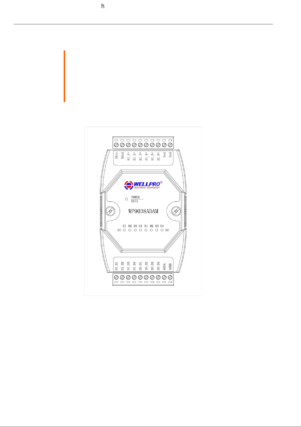
WP9038ADAM
User’s Manual
Version 1.42
https://www.wy-international.com/
https://www.ebay.com/str/tiamofaye/
WP9038ADAM User’s Manual V1.42
1
、
Product description
6 c single terminal analog input (DC 0-20mA/4-20mA),using independent 12 bit industrial AD collection c ip
4 c optoelectronic isolation digital input and output (NPN transistor open collector output)
Using RS485 MODBUS RTU communication standard. It can be netted wit configuration software, PLC and industry
touc pad
Communication, input and output status LED
Communication circuit designed for lig tening protection and interference immunity
Could be used for signal collection and control of Industrial field apparatus
3 Year’s quality assurance for normal use
2
、
Specification
Analog input c annel 6 c single terminal
Analog input type DC 0-20mA/4-20mA
Analog input accuracy ±0.02mA
Digital input c annel 4 c (active low)
Digital output c annel 4 c (NPN transistor open collector output, 500mA)
Working Temperature -20
~
70
℃
External power supply DC 9V
~
30V/2W
Isolation protect 1500VDC
Installation met od Standard DIN slide rail or screw
Dimension 125×73×35mm
3
、
Interface definition
AVcc External PSU positive terminal input
AGnd External PSU negative terminal input
AI_1+ Positive terminal of 1
st
analog input
AI_2+ Positive terminal of 2
nd
analog input
AI_3+ Positive terminal of 3
rd
analog input
AI_4+ Positive terminal of 4
t
analog input
AI_5+ Positive terminal of 5
t
analog input
AI_6+ Positive terminal of 6
t
analog input
Gnd signal ground, connect to negative terminal of analog input
Gnd signal ground, connect to negative terminal of analog input
DI_01 1
st
digital input
DI_02 2
nd
digital input
DI_03 3
rd
digital input
DI_04 4
t
digital input
DO_01 1
st
digital output
DO_02 2
nd
digital output
DO_03 3
rd
digital output
DO_04 4
t
digital output
485A RS485 signal A+
485B RS485 signal B-
4
、
Digital/analog application diagram
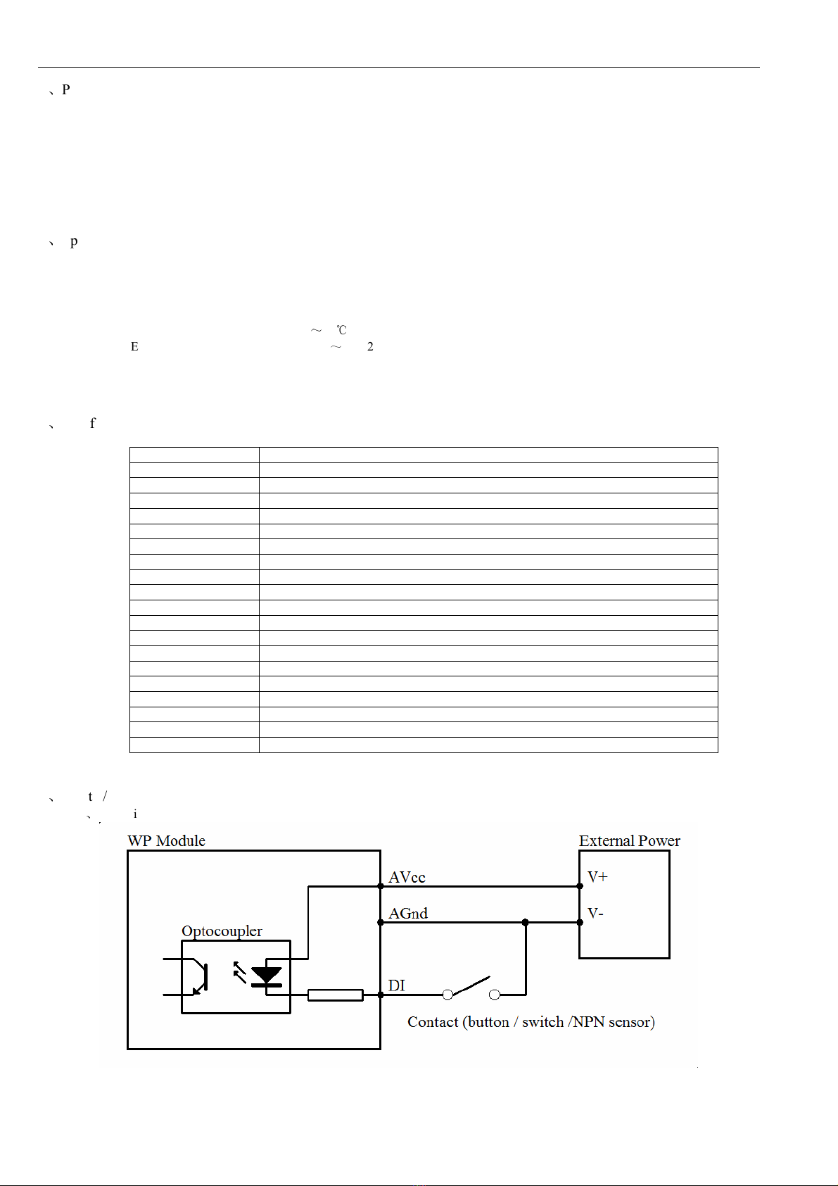
4.1
、
digital input diagram
WP9038ADAM User’s Manual V1.42
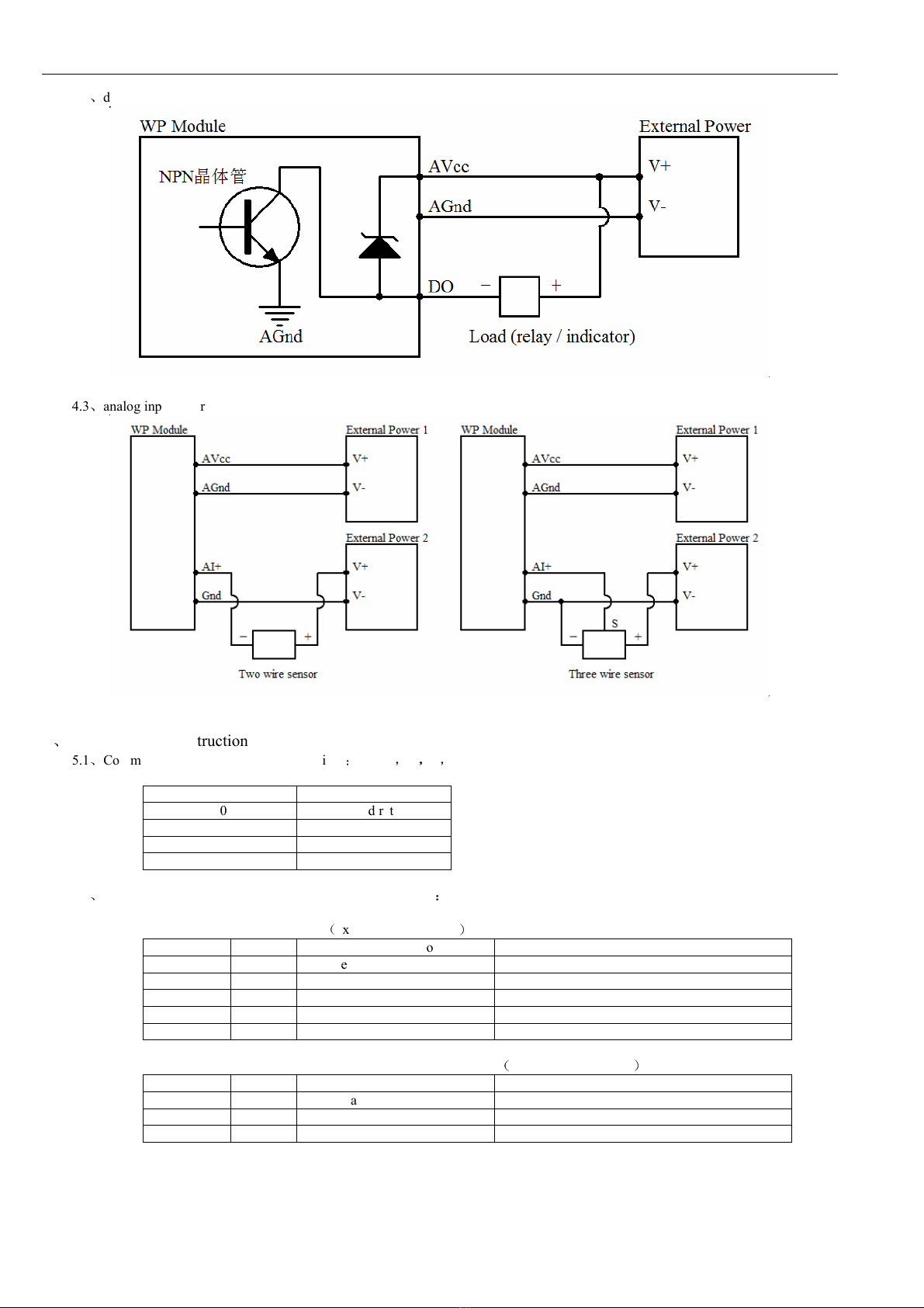
4.2
、
digital output diagram
4.3
、
analog input diagram
5
、
Communication Instruction
5.1
、
Communication parameter (default setting)
:
9600
,
N
,
8
,
1
Parameter Description
9600 baud rate
N(no c eck) c eck bit
8 data bit
1 stop bit
5.2
、
Command for collecting t e input signal of analog quantity
:
Send: 01 03 00 00 00 06 C5 C8
(
example/ exadecimal
)
data byte data description remark
01 1 module address address range:01-FE
03 1 function code 03-read register
0000 2 register address (4x mode) 0000-analog input address of first register
0006 2 reading lengt 0006-read 6 registers
C5C8 2 CRC c eck code CRC c eck code for all data
Receive: 01 03 0C 07 69 00 00 00 00 00 00 00 00 00 00 B6 26
(
example/ exadecimal
)
data byte data description remark
01 1 module address address range:01-FE
03 1 function code 03-read register
0C 1 byte numbers 0C-read 12 bytes

WP9038ADAM User’s Manual V1.42
0769
0000
0000
0000
0000
0000
16 read data 0769-read data from t e first analog input
0000-read data from t e second analog input
0000-read data from t e t ird analog input
0000-read data from t e fourt analog input
0000-read data from t e fift analog input
0000-read data from t e sixt analog input
B626 2 CRC c eck code CRC c eck code for all data
T e recieved command means t e data of t e first analog input is “0769”,and it is equal to 1897 in decimal,t en substitute into
t e fomula: I=(DATA*20)/4095=(1897*20)/4095≈9.26mA.T e current in t e ot er c annel is 0mA.
5.3
、
Command for digital input collection
:
Send: 01 02 00 00 00 04 79 C9
(
example/ exadecimal
)
data byte data description remark
01 1 module address Address range 01-FE
02 1 function code 02-read input bit
0000 2 input address(1x mode) 0000-initial address of input bit
0004 2 read lengt of input bit 0004-read 4 input bits
79C9 2 CRC c eck code CRC c eck code for all data
Receive: 01 02 01 05 61 8B
(
example/ exadecimal
)
data byte data description remark
01 1 module address Address range 01-FE
02 1 function code 02-read input bit
01 1 byte numbers 01-read one byte lengt
05 1 read data 05-read input bit status
618B 2 CRC c eck code CRC c eck code for all data
Converting reading data “05” to 2 exadecimal results “00000101”, last 4 numbers are active. From left to rig t, it represents
t e 4 digital input c annel status DI_04~ DI_01. Here it means DI_03
、
DI_01 ave input but ot ers no.
5.4
、
Command for digital output (several controls)
:
Send: 01 0F 00 00 00 04 01 03 7E 97
(
example/ exadecimal
)
data byte data description remark
01 1 module address Address range 01-FE
0F 1 function code 0F-write multiple coil
0000 2 coil address(0x mode) 0000-initial address of coil
0004 2 write coil lengt 0004-write 4 coils
01 1 write data byte 01-write one byte data
03 2 data writing 03-write output state of 4 coil
7E97 2 CRC c eck code CRC c eck code for all data
Receive: 01 0F 00 00 00 04 54 08
(
example/ exadecimal
)
Converting reading data “03” to 2 exadecimal results “0000 0011”, last 4 numbers are active. From left to rig t, it represents
t e 4 digital output c annel status DI_04 ~ DI_01. Here it means DO_02
、
DO_01 ave output but ot ers no. W en module
receives correct command, it will make corresponding actions and send response back to t e master. T is is successful
communication.
5.5
、
Command for digital output (single control)
:
Send: 01 05 00 00 FF 00 8C 3A
(
example/ exadecimal
)
data byte data description remark
01 1 module address Address range 01-FE
05 1 function code 05-write single coil
0000 2 coil address(0x mode) 0000-digital output(DO_01)coil address
0001-digital output(DO_02)coil address
0002-digital output(DO_03)coil address
0003-digital output(DO_04)coil address
FF00 2 data writing FF00-coil open
,
0000-coil close
8C3A 2 CRC c eck code CRC c eck code for all data
Receive: 01 05 00 00 FF 00 8C 3A
(
example/ exadecimal
)

WP9038ADAM User’s Manual V1.42
W en module receives correct command, it will make corresponding actions and send response back to t e master. T is is
successful communication.
5.6
、
Command for state collection of digital output
:
Send: 01 01 00 00 00 04 3D C9
(
example/ exadecimal
)
data byte data description remark
01 1 module address Address range 01-FE
01 1 function code 01-read coil state
0000 2 coil address(0x mode) 0000-initial address of coil
0004 2 read coil lengt 0004-read 4 coils state
3DC9 2 CRC c eck code CRC c eck code for all data
Receive: 01 01 01 03 11 89
(
example/ exadecimal
)
data byte data description remark
01 1 module address Address range 01-FE
01 1 function code 01-read coil state
01 1 byte numbers 01-read one byte data
03 1 read data 03-read coil state
1189 2 CRC c eck code RC c eck code for all data
Converting reading data “03” to 2 exadecimal results “0000 0011”. From left to rig t, it represents t e 4 digital output c annel
status DI_04 ~ DI_01. Here it means DO_02
、
DO_01 ave output but ot ers no.
5.7
、
command for module address setting
:
Send
:
00 06 00 64 00 01 08 04
(
example/ exadecimal
)
date byte data description remark
00 1 module address 00-group sending
06 1 function code 06-write single register
0064 2 register address (4x mode) 0064-modify module address
0001 2 data writing set new address for module, range 0001-00FE
0804 2 CRC c eck code CRC c eck code for all data
Receive
:
00 06 00 64 00 01 08 04
(
example/ exadecimal
)
T is command means to send a code to a module, set t e module address as 01, t is setting could be saved w en power off;
default address of module is 01,eac module address could be assigned separately w en using multiple modules for
network.Attentions is required t at only one module could be used in 485 network w en using multiple address sending,
ot erwise all t e modules will s are t e same address in 485 network. W en module receives correct command, it will make
corresponding actions and send response back to t e master. T is is successful communication.
5.8
、
Command for communication parameter setting
:
Send
:
01 06 00 65 00 02 18 14
(
example/ exadecimal
)
data byte data description remark
01 1 module address address range:01-FE
06 1 function code 06-write single register
0065 2 register address (4x mode) 0065-modify communication parameter
0002 2 data writing 0001-set communication parameter 4800,N(no
c eck) ,8,1
0002-set communication parameter 9600,N(no
c eck) ,8,1
0003-set communication parameter 19200,N(no
c eck) ,8,1
0004-set communication parameter 38400,N(no
c eck) ,8,1
0005-set communication parameter 4800,E(even
c eck) ,8,1
0006-set communication parameter 9600,E(even
c eck) ,8,1
0007-set communication parameter 19200,E(even
c eck) ,8,1
0008-set communication parameter 38400,E(even
c eck) ,8,1
1814 2 CRC c eck code CRC c eck code for all data
WP9038ADAM User’s Manual V1.42
Receive
:
01 06 00 65 00 02 18 14
(
example/ exadecimal
)
T is command means to send a code to t e module and set t e communication parameter as “9600, N (No c eck), 8, 1”.T is
setting could be saved w en power off. T e default communication parameter is “9600, N (no c eck), 8, 1”. Attention is
required, w en electing t e correct communication parameter in communication setting and restarting t e communication
terminal, setting will be done.Normally, t e lower of baud rate, t e lower of t e transaction speed but t e ig er of transaction
stability. T e opposite is also true.W en module receives correct command, corresponding action will be taken and response
will be sent back to t e master. T is is successful communication.
6
、
Indicator LED description
W en module powered on, Led is green.
W en module is under communication, LED is twinkling.
w en module receive correct command, LED is green.
w en module receive incorrect command or command for ot er modules, LED is red.
7
、
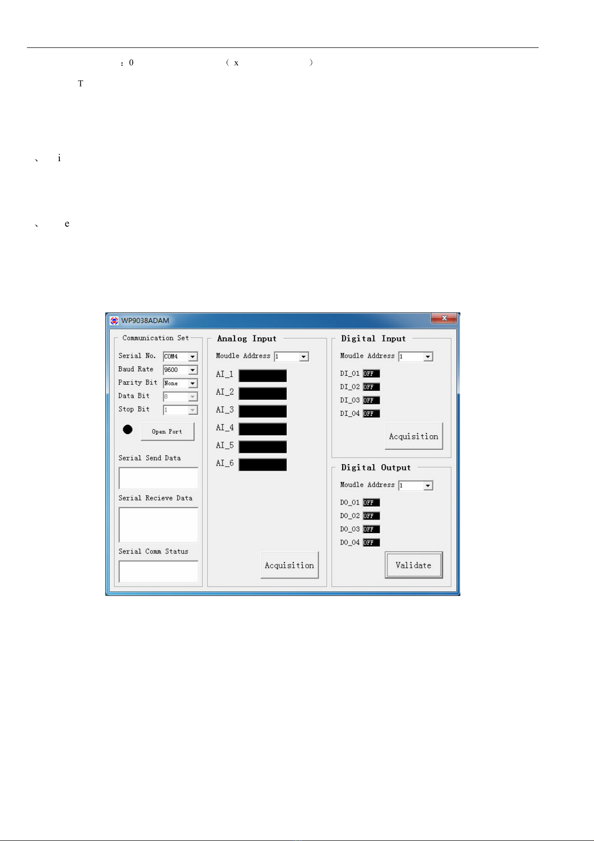
PC debugging instruction
T is module provides software for parameter setting and function test. Please follow t e steps below:
Connect t e module and computer using RS485 converter.
Connect 12V or 24V power wit module and power on. To avoid any unnecessary damage, please make sure t e power
positive & negative terminals are correctly connected before power on.
Open t e software, select t e correct module number, you will see t e window of function test or parameter setting.
Set correct parameter, open communication interface.
Select corresponding setting, collection and control items.

WP9038ADAM User’s Manual V1.42
8
、
RS485 network diagram
https://www.wy-international.com/
https://www.ebay.com/str/tiamofaye/
Email: [email protected]
Table of contents
Other Wellpro Control Unit manuals

Popular Control Unit manuals by other brands

Festo
Festo Compact Performance CP-FB6-E Brief description

Elo TouchSystems
Elo TouchSystems DMS-SA19P-EXTME Quick installation guide

JS Automation
JS Automation MPC3034A user manual

JAUDT
JAUDT SW GII 6406 Series Translation of the original operating instructions

Spektrum
Spektrum Air Module System manual

BOC Edwards
BOC Edwards Q Series instruction manual

KHADAS
KHADAS BT Magic quick start

Etherma
Etherma eNEXHO-IL Assembly and operating instructions

PMFoundations
PMFoundations Attenuverter Assembly guide

GEA
GEA VARIVENT Operating instruction

Walther Systemtechnik
Walther Systemtechnik VMS-05 Assembly instructions

Altronix
Altronix LINQ8PD Installation and programming manual


