Wen 4280 User manual

8-INCH VARIABLE SPEED
BENCH GRINDER
Instruction Manual
IMPORTANT: Your new tool has been engineered and manufactured to WEN’s highest standards for dependability,
ease of operation, and operator safety. When properly cared for, this product will supply you years of rugged,
trouble-free performance. Pay close attention to the rules for safe operation, warnings, and cautions. If you use
your tool properly and for its intended purpose, you will enjoy years of safe, reliable service.
NEED HELP? CONTACT US!
Have product questions? Need technical support? Please feel free to contact us:
For replacement parts and the most up-to-date instruction manuals, visit WENPRODUCTS.COM
MODEL 4280, BG4280

CONTENTS
WELCOME 3
Introduction ..................................................................................................... 3
Specifications................................................................................................... 3
SAFETY 4
General Safety Rules........................................................................................ 4
Bench Grinder Safety Warnings ....................................................................... 6
Electrical Information....................................................................................... 8
BEFORE OPERATING 9
Unpacking & Packing List.................................................................................9
Know Your Bench Grinder.............................................................................. 10
Assembly & Adjustments............................................................................... 11
OPERATION & MAINTENANCE 12
Operation ....................................................................................................... 12
Maintenance....................................................................................................13
Troubleshooting Guide................................................................................... 15
Exploded View & Parts List.............................................................................16
Warranty Statement ........................................................................................18
To purchase accessories and replacement parts for your tool, visit WENPRODUCTS.COM
Cast Iron Bench Grinder Stand (Model 4288T)
2

SPECIFICATIONS
INTRODUCTION
Thanks for purchasing the WEN Bench Grinder. We know you are excited to put your tool to work, but first, please
take a moment to read through the manual. Safe operation of this tool requires that you read and understand this
operator’s manual and all the labels affixed to the tool. This manual provides information regarding potential safety
concerns, as well as helpful assembly and operating instructions for your tool.
NOTE: The following safety information is not meant to cover all possible conditions and situations that may occur.
WEN reserves the right to change this product and specifications at any time without prior notice.
At WEN, we are continuously improving our products. If you find that your tool does not exactly match this manual,
please visit wenproducts.com for the most up-to-date manual or contact our customer service at 1-800-232-1195.
Keep this manual available to all users during the entire life of the tool and review it frequently to maximize
safety for both yourself and others.
Indicates danger, warning, or caution. The safety symbols and the explanations with them deserve your
careful attention and understanding. Always follow the safety precautions to reduce the risk of fire, electric shock
or personal injury. However, please note that these instructions and warnings are not substitutes for proper ac-
cident prevention measures.
Model Number 4280, BG4280
Motor 120V, 60 Hz, 5A
Wheel Speed 2000 - 3400 RPM
Grinding Wheel Size 3 in. x 1 in,
Arbor Size 5/8 Inch
Arbor Thread M16-2.0
Wheel Grits #36 and #80
Product Weight 41 Pounds
Product Dimensions 17 in. x 18.1 in. x 13 in.
3

GENERAL SAFETY RULES
WORK AREA SAFETY
1. Keep work area clean and well lit. Cluttered or dark
areas invite accidents.
2. Do not operate power tools in explosive atmo-
spheres, such as in the presence of flammable liquids,
gases or dust. Power tools create sparks which may ig-
nite the dust or fumes.
3. Keep children and bystanders away while operating
a power tool. Distractions can cause you to lose control.
ELECTRICAL SAFETY
1. Power tool plugs must match the outlet. Never mod-
ify the plug in any way. Do not use any adapter plugs
with earthed (grounded) power tools. Unmodified plugs
and matching outlets will reduce risk of electric shock.
2. Avoid body contact with earthed or grounded surfac-
es such as pipes, radiators, ranges and refrigerators.
There is an increased risk of electric shock if your body
is earthed or grounded.
3. Do not expose power tools to rain or wet conditions.
Water entering a power tool will increase the risk of elec-
tric shock.
4. Do not abuse the cord. Never use the cord for car-
rying, pulling or unplugging the power tool. Keep cord
away from heat, oil, sharp edges or moving parts.
Damaged or entangled cords increase the risk of electric
shock.
5. When operating a power tool outdoors, use an ex-
tension cord suitable for outdoor use. Use of a cord
suitable for outdoor use reduces the risk of electric
shock.
6. If operating a power tool in a damp location is un-
avoidable, use a ground fault circuit interrupter (GFCI)
protected supply. Use of a GFCI reduces the risk of elec-
tric shock.
PERSONAL SAFETY
1. Stay alert, watch what you are doing and use com-
mon sense when operating a power tool. Do not use a
power tool while you are tired or under the influence
of drugs, alcohol or medication. A moment of inatten-
tion while operating power tools may result in serious
personal injury.
2. Use personal protective equipment. Always wear
eye protection. Protective equipment such as a respira-
tory mask, non-skid safety shoes and hearing protection
used for appropriate conditions will reduce the risk of
personal injury.
3. Prevent unintentional starting. Ensure the switch is
in the off-position before connecting to power source
and/or battery pack, picking up or carrying the tool.
Carrying power tools with your finger on the switch or
energizing power tools that have the switch on invites
accidents.
4. Remove any adjusting key or wrench before turning
the power tool on. A wrench or a key left attached to a
rotating part of the power tool may result in personal
injury.
5. Do not overreach. Keep proper footing and balance
at all times. This enables better control of the power
tool in unexpected situations.
6. Dress properly. Do not wear loose clothing or jew-
elry. Keep your hair and clothing away from moving
parts. Loose clothes, jewelry or long hair can be caught
in moving parts.
Safety is a combination of common sense, staying alert and knowing how your item works. The term “power tool”
in the warnings refers to your mains-operated (corded) power tool or battery-operated (cordless) power tool.
SAVE THESE SAFETY INSTRUCTIONS.
WARNING! Read all safety warnings and all instructions. Failure to follow the warnings and instructions may
result in electric shock, fire and/or serious injury.
4

GENERAL SAFETY RULES
7. If devices are provided for the connection of dust
extraction and collection facilities, ensure these are
connected and properly used. Use of dust collection
can reduce dust-related hazards.
POWER TOOL USE AND CARE
1. Do not force the power tool. Use the correct power
tool for your application. The correct power tool will
do the job better and safer at the rate for which it was
designed.
2. Do not use the power tool if the switch does not turn
it on and off. Any power tool that cannot be controlled
with the switch is dangerous and must be repaired.
3. Disconnect the plug from the power source and/or
the battery pack from the power tool before making
any adjustments, changing accessories, or storing
power tools. Such preventive safety measures reduce
the risk of starting the power tool accidentally.
4. Store idle power tools out of the reach of children
and do not allow persons unfamiliar with the power
tool or these instructions to operate the power tool.
Power tools are dangerous in the hands of untrained us-
ers.
5. Maintain power tools. Check for misalignment or
binding of moving parts, breakage of parts and any
other condition that may affect the power tool’s opera-
tion. If damaged, have the power tool repaired before
use. Many accidents are caused by poorly maintained
power tools.
6. Keep cutting tools sharp and clean. Properly main-
tained cutting tools with sharp cutting edges are less
likely to bind and are easier to control.
7. Use the power tool, accessories and tool bits, etc.
in accordance with these instructions, taking into ac-
count the working conditions and the work to be per-
formed. Use of the power tool for operations different
from those intended could result in a hazardous situa-
tion.
8. Use clamps to secure your workpiece to a stable
surface. Holding a workpiece by hand or using your
body to support it may lead to loss of control.
9. KEEP GUARDS IN PLACE and in working order.
SERVICE
1. Have your power tool serviced by a qualified repair
person using only identical replacement parts. This
will ensure that the safety of the power tool is main-
tained.
CALIFORNIA PROPOSITION 65 WARNING
Some dust created by power sanding, sawing, grinding,
drilling, and other construction activities may contain
chemicals, including lead, known to the State of Califor-
nia to cause cancer, birth defects, or other reproductive
harm. Wash hands after handling. Some examples of
these chemicals are:
• Lead from lead-based paints.
• Crystalline silica from bricks, cement, and other
masonry products.
• Arsenic and chromium from chemically treated
lumber.
Your risk from these exposures varies depending on
how often you do this type of work. To reduce your ex-
posure to these chemicals, work in a well-ventilated area
with approved safety equipment such as dust masks
specially designed to filter out microscopic particles.
Safety is a combination of common sense, staying alert and knowing how your item works. The term “power tool”
in the warnings refers to your mains-operated (corded) power tool or battery-operated (cordless) power tool.
SAVE THESE SAFETY INSTRUCTIONS.
WARNING! Read all safety warnings and all instructions. Failure to follow the warnings and instructions may
result in electric shock, fire and/or serious injury.
5

BENCH GRINDER SAFETY
1. This bench grinder is designed for sharpening and
honing cutting tools, using the appropriate accessories.
Using the machine for any other purpose for which it
is not designed may result in serious injuries, machine
damage and voiding of the warranty.
2. Grinding wheel safety:
• Only use grinding wheels rated for a speed higher
than 3450 RPM (maximum RPM of the tool).
• Inspect wheels for cracks or fragments before start-
ing the machine. Replace damaged wheels immedi-
ately. Never use a questionable grinding wheel, as
the RPM of the machine can send broken wheel frag-
ments flying at high speeds.
• Do not use a wheel that vibrates. If a wheel vibrates,
it may be that the bearings of the shaft need replac-
ing.
• Check that the grinding stone can rotate smoothly
before starting the machine.
• The grinding wheel is for grinding. Never attempt to
cut anything with the grinding wheel.
3. The use of accessories or attachments not recom-
mended by the manufacturer may result in a risk of per-
sonal injury.
4. DANGER! Fire Hazard. Do not grind or polish magne-
sium or magnesium alloys.
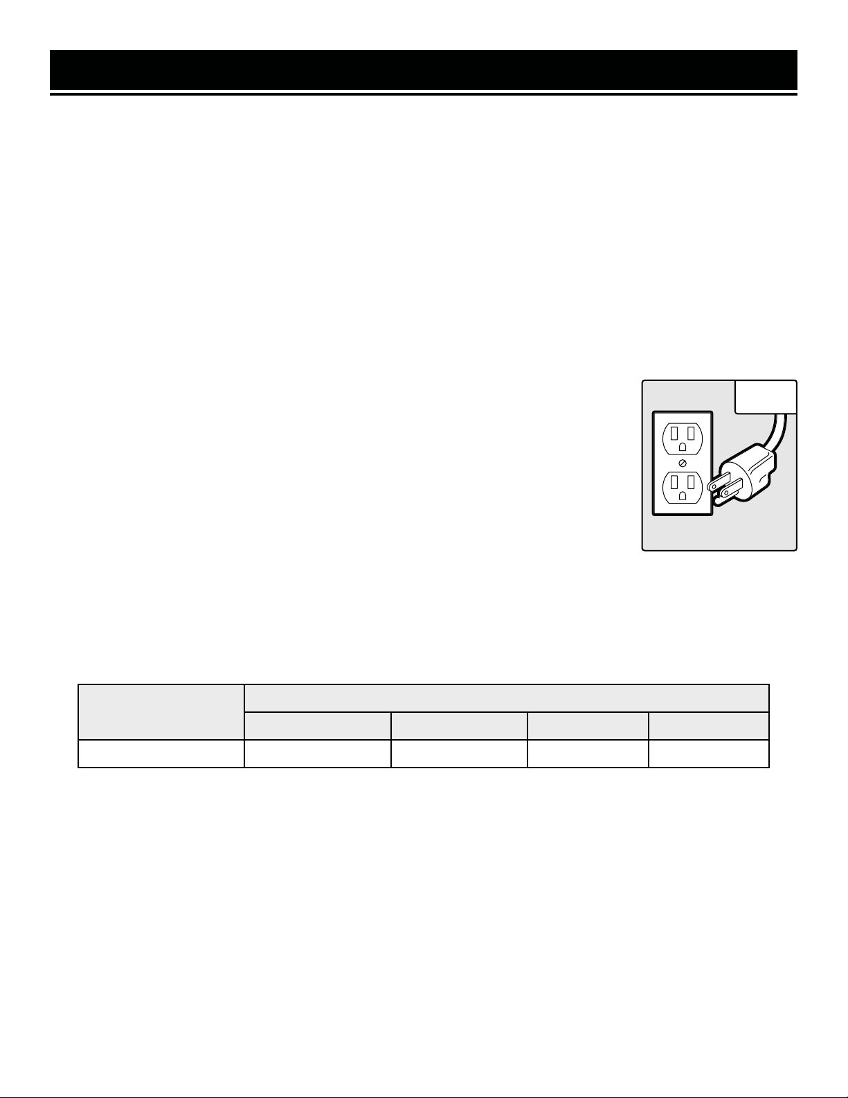
5. Preventing accidental starting. Make sure the power
switch is in the OFF position prior to plugging in the ma-
chine. Always make sure the power switch is in the OFF
position and the machine is unplugged when doing any
cleaning, adjustments, assembly, setup operations, or
when not in use.
PERSONAL SAFETY
1. Operate in a well ventilated area. Keep the floor
area around the bench grinder level and free of
slippery substances or other tripping hazards.
2. Wear ANSI-approved safety goggles to protect your
eyes from sparks and chips. Use hearing protection to
protect yourself from hearing loss.
3. DO NOT wear loose clothing or jewelry as they might
get drawn in by the tool. Tie back long hair.
4. People with pacemakers should consult their
physician(s) before use. Electromagnetic fields in close
proximity to pacemakers could cause pacemaker inter-
ference or pacemaker failure.
5. Chips are harmful to your health. Use NIOSH-approved
dust masks or other respiratory protection during opera-
tion and cleaning.
6. Always turn off and unplug the bench grinder before
making any adjustments or repair tasks. Never adjust the
bench grinder or the workpiece while the tool is running.
PREPARING THE BENCH GRINDER
When transporting the bench grinder, carry it by the
base. Never carry the device by its guards or its acces-
sories.
1. Examine the bench grinder for any damaged or miss-
ing parts. Replace or repair damaged parts before op-
eration. Periodically check that all nuts, bolts and other
fasteners are properly tightened.
2. Do not operate this tool until it is completely assem-
bled and installed according to the instructions. Make
sure all adjustments are correct and all connections are
tight. Keep all guards in place.
DURING OPERATION
1. Never start the machine with any load already applied
to either grinding wheel. Stand to the side of the bench
grinder during start-up. Switch it ON and let the bench
grinder reach full speed for roughly one minute to warm
up the wheel and to ensure proper operation.
2. Never grind on a cold wheel. Run the bench grinder
for one full minute before applying the workpiece. Cold
wheels have an increased likelihood of chipping during
operation.
3. Only grind on the face of the grinding wheel. Do not
grind on the side of the wheel.
BENCH GRINDER SAFETY WARNINGS
WARNING! Do not operate the power tool until you have read and understood the following instructions and
the warning labels.
6

BENCH GRINDER SAFETY WARNINGS
WARNING! Do not operate the power tool until you have read and understood the following instructions and
the warning labels.
DURING OPERATION (CONT.)
4. Keep clear of moving parts. Keep arms, hands and
other vital appendages away from the grinding and hon-
ing wheel. Do not reach behind or beneath the rotating
wheel. Avoid awkward operation and hand positions. An
accident could easily send the operator’s hand into the
wheel.
5. If you are interrupted when operating the bench grind-
er, complete the process and switch the bench grinder
off before looking up.
6. Always hold the workpiece firmly against the tool rest.
7. Never attempt to cut anything with the grinding wheel.
8. Do not use the bench grinder unless all guards are in
place. Do not operate with any guard disabled, damaged,
or removed. Moving guards must move freely and close
instantly.
9. Disconnect the power source and allow the wheels to
come to a complete stop before making any adjustments
to either the machine or the grinding wheels.
10. Clean the machine thoroughly when changing ma-
terial types in workpieces. Combining certain materials
can increase the chances of an explosion or fire hazard.
11. Should any component of your bench grinder be
missing/damaged or fail in any way, shut off the switch
and remove the plug from power supply outlet. Have a
certified technician replace the missing, damaged, or
failed parts using only identical replacement parts before
resuming operation.
7

ELECTRICAL INFORMATION
AMPERAGE REQUIRED GAUGE FOR EXTENSION CORDS
25 ft. 50 ft. 100 ft. 150 ft.
5A 18 gauge 16 gauge 16 gauge 14 gauge
3. Check
with a licensed electrician or service personnel if you do not completely
understand the grounding instructions or whether the tool is properly grounded.
4. Use only three-wire extension cords
that have three-pronged plugs and outlets
that accept the tool’s plug (INSERT CR). Repair or replace a damaged or worn cord
immediately.
CAUTION!
In all cases, make certain the outlet in question is properly grounded. If
you are not sure, have a licensed electrician check the outlet.
GUIDELINES AND RECOMMENDATIONS FOR EXTENSION CORDS
GROUNDING INSTRUCTIONS
In the event of a malfunction or breakdown
, grounding provides the path of least resistance for an electric
current and reduces the risk of electric shock. This tool is equipped with an electric cord that has an
equipment grounding conductor and a grounding plug. The plug MUST be plugged into a matching outlet
that is properly installed and grounded in accordance with ALL local codes and ordinances.
1. Do not modify the plug provided.
If it will not fit the outlet, have the proper outlet installed by a licensed
electrician.
2. Improper connection
of the equipment grounding conductor can result in electric shock. The conductor
with the green insulation (with or without yellow stripes) is the equipment grounding conductor. If repair or
replacement of the electric cord or plug is necessary, DO NOT connect the equipment grounding conductor
to a live terminal.
1. Examine extension cord before use. Make sure your extension cord is properly wired and in good condition.
Always replace a damaged extension cord or have it repaired by a qualified person before using it.
2. Do not abuse extension cord. Do not pull on cord to disconnect from receptacle; always disconnect by pulling on
plug. Disconnect the extension cord from the receptacle before disconnecting the product from the extension cord.
Protect your extension cords from sharp objects, excessive heat and damp/wet areas.
3. Use a separate electrical circuit for your tool. This circuit must not be less than a 12-gauge wire and should be
protected with a 15A time-delayed fuse. Before connecting the motor to the power line, make sure the switch is in
the OFF position and the electric current is rated the same as the current stamped on the motor nameplate. Running
at a lower voltage will damage the motor.
Fig. 1
When using an extension cord, be sure to use one heavy enough to carry the current your product will draw. An un-
dersized cord will cause a drop in line voltage resulting in loss of power and overheating. The table below shows the
correct size to be used according to cord length and ampere rating. When in doubt, use a heavier cord. The smaller
the gauge number, the heavier the cord.
8

UNPACKING & PACKING LIST
UNPACKING
With the help of a friend or trustworthy foe, carefully remove the Bench Grinder from the packaging. Make sure to
take out all contents and accessories. Do not discard the packaging until everything is removed. Check the packing
list below to make sure you have all of the parts and accessories. If any part is missing or broken, please contact
PACKING LIST
WARNING! Do not plug in or turn on the tool until it is fully assembled according to the instructions. Failure
to follow the safety instructions may result in serious personal injury.
Accessories
Components
Bench Grinder
Tool Rest Support
Lock Knobs
Right Tool Rest
Support
Left Tool Rest
Support
Right Tool Rest
Left Tool Rest
Drill Bit
Sharpening Rest
Left Spark Arrestor
Right Spark Arrestor
Wheel Dresser
Right Eye Guard
Left Eye Guard
Eye Shield Knobs
Hardware
1. M5x10 Screw Assemblies...................................4
2. M6x12 Square Neck Bolts...................................2
3. D6 Flat Washers..................................................4
9
Wire Wheel Spacer

KNOW YOUR BENCH GRINDER
Eye Shield
TOOL PURPOSE
Sharpen bits, drill bits, chisels, gouges, and other cutting tools all with your WEN Bench Grinder. Refer to the fol-
lowing diagrams to become familiarized with all the parts and controls of your bench grinder. The components will
be referred to later in the manual for assembly and operation instructions.
Grinding Wheel
Wheel Dresser
Tool Rest
Variable Speed Knob
Quenching Pot
Power Switch
Drill Bit
Sharpening Rest
Eye Shield
Work Lamp
10

1
2
3
4
5
6
1
2
3
4
5
6
TOOL RESTS
Two different tool rests are included with this bench
grinder.
To install these tool rests:
1. Attach the tool rest support (Fig. A - 1) to the in-
side surface of the wheel cover using a flat washer
(Fig. A - 2) and a hex head screw (Fig. A - 3).
2. Attach the tool rest (Fig. A - 4) to the tool rest
support (Fig A - 1) using a flat washer (Fig. A - 5)
and an adjustment knob (Fig. A - 6).
3. Adjust each tool rest until its inside edge is 1/16
of an inch from the grinding wheel. Tighten the hex
head screws holding the supports in place.
4. If you are wanting to sharpen drill bits, there
is also a drill bit sharpening plate included in this
package. Attach it to the tool rest support in the
same way as you would the regular tool rests. The
divot running diagonally down the center of the tool
rests allows for easy sharpening of the tips of bits.
Only use this plate for sharpening drill bits.
SPARK ARRESTORS AND EYE SHIELDS
1. Attach the spark arrestors (Fig. B - 1) to the inside
surface of the wheel covers using two screws and
washers (Fig. B - 2).
2. Position said spark arrestors so that the lower
edge is 1/16 of an inch from the grinding wheel.
Firmly tighten the hex head screws.
3. Attach the eye shields (Fig. B - 3) to the spark ar-
restor by inserting a carriage head screw (Fig. B - 4)
through the eye shield and the spark arrestor.
4. Position the eye shield into its desired position.
Assemble the flat washer (Fig. B - 5) and lock knob
(Fig. B - 6) to the carriage head screw and tighten
until the eye shield no longer moves.
ASSEMBLY & ADJUSTMENTS
Fig. A
Fig. B
2
11

WORKLIGHT
The bench grinder provided has a flexible work light to maximize visibility during operation. A light bulb for the
flexible work light is not included. Use a 120 Volt, 40 watt or less track light bult (type R20, medium base) for the
onboard lamp. Make sure the bulb does not protrude past the rim of the light’s housing.
The flexible work light can be positioned in whatever direction you choose. Using the switch located on the top of
the housing will turn the light on and off.
ASSEMBLY & ADJUSTMENTS
WARNING! The light’s housing will remain hot for a few minutes after operation. Make sure to not touch
either the bulb or the housing during or directly after use.
PERMANENT MOUNTING
Firmly attach the grinder to a reliable work surface using the mounting pads and the included holes along the base
of the grinder (mounting hardware not included). This will prevent the possibility of vibration, walking or tipping
during operation.
WARNING! Do not operate this machine without first attaching the base to a reliable surface.
1. Turn the variable speed knob to its lowest setting before turning on the bench grinder.
2. To operate the bench grinder, always wear safety glasses and turn the tool on while standing to the side of the
grinder (as opposed to in front). Allow it to reach full speed before grinding.
3. Once the grinder is up and running, set the grinder to your desired speed. The lowest speed setting should be
used for light grinding, sharpening, and paint/rust removal. The highest speed should be used for deburring, mate-
rial removal and other heavier grinding tasks.
4. Hold the work piece firmly against the tool rest. Hold very small pieces with pliers or other suitable clamps.
5. Feed the work piece smoothly and evenly into the grinding wheel. Move it back and forth as to not burn any one
area of the surface and also to make for even grinding.
6. Move the work piece slowly and avoid jamming the work piece against the wheel. If the wheel tends to slow down
from excessive force, you should occasionally release the pressure to let the wheel return to full speed.
7. Grind only on the face of the grinding wheel; never the side of it
8. Place the hot end of the workpiece into the quenching tray to cool it off if you so choose.
9. Once grinding operations are complete, return the variable speed knob to its lowest setting. Once the wheels have
reached their new low speed, turn the bench grinder off and unplug it. Avoid contact with the bench grinder’s hous-
ing until it has cooled down completely.
OPERATION
12

OPERATION
SHARPENING GUIDE:
SCISSORS
If possible, take the scissors apart to make the sharpening operation easier and safer. Remove material only from
the outside surface and work from the heavy end of the blade toward the tip.
KNIVES
Remove metal from both faces of most knives, working from the heavy end of the blade toward the tip.
SCREWDRIVERS
The end of a properly sharpened screwdriver will be a perfectly flat rectangle, perpendicular to the center line of the
shank. The two sides and two faces will taper outward from the edge of the shoulder or shank. They should be flat
with perpendicular intersecting faces. Hold each face of the screwdriver against the wheel to true it up, then ease
the end straight into the stone to grind it true.
LAWN MOWER BLADES
Lawn mower blades are usually sharpened on only one side and dressed up slightly on the other. After sharpening,
be sure to balance the blade by removing additional material from the heavy end. There are a number of inexpensive
cone balancers on the market for this purpose. Unbalanced blades can cause serious crank shaft damage to your
lawn mower. Always remove spark plug wires or battery from the mower before servicing the blades to prevent ac-
cidental startups.
DRILL BITS
Use the drill bit tool rest to provide angled support to drill bits during grinding operation. The angled divot running
through the rest allows for a cradle for drill bits during sharpening operations.
Before using, check to make sure parts are not damaged, missing, or worn. Check for alignment of moving parts,
binding of moving parts, improper mounting, or any other conditions that may affect the sharpener’s operation. If
any of these conditions exist, do not use until parts are replaced or the sharpener is properly repaired. Frequently
blow or vacuum dust from all surfaces and the motor housing.
MAINTENANCE
WARNING! For your own safety, turn the switch OFF and remove the plug from the electrical outlet before
adjusting or performing maintenance or lubrication work on the sharpener.
WARNING! Any attempt to repair or replace electrical parts on this tool may be hazardous. Repairs should
be done by a qualified service technician only.
1. Regularly check the tool and use a soft brush to remove accumulated dust. Wear safety goggles to protect your
eyes while cleaning.
2. If the body of the grinder needs cleaning, wipe it down with a soft, damp cloth. A mild detergent can be used.
Do not use alcohol, petrol or other similar cleaning agents. Do not make contact with the grinding wheels with any
damp cloth.
3. Always make sure the eye shields are transparent and not blocking the view of the grinding wheel.
13

1
2
3
4. In normal use, grinding wheels may become cracked, grooved, rounded at the edges, chipped, out of true or
loaded with foreign material. Cracked wheels should be replaced IMMEDIATELY. While any of the other conditions
can be remedied with a dressing tool (included), new wheels sometimes require dressing to make them round.
5. If you must replace a wheel be sure to obtain one with a safe rated speed at least as high as the “NO LOAD” RPM
marked on your grinder’s nameplate. Test new wheels for cracks and maintain the existing sequence of retaining
hardware. Be sure the tool is unplugged before attempting repairs.
6. This unit has sealed lubrication within the bearings in the motor housing. No additional lubrication is required.
MAINTENANCE
Fig. C
1
1
CHANGING THE GRINDING WHEELS
Grinding wheels should be inspected before each use.
Store the grinding wheels to prevent them from the
potential hazards of moisture, containments and other
damage.
To replace a grinding wheel:
1. Disconnect the grinder from the power supply.
2. Rotate the eye shield out of the way in order to ac-
cess the tool rest.
3. Loosen the tool rest knob and position the tool rest
away from the grinding wheel.
4. Remove the three screws (Fig. C - 1) found around
the outside of the wheel guard in order to remove the
wheel cover.
5. Using two wrenches, remove the arbor hex nut (Fig.
C - 2) found on the outside edge of the grinding wheel.
NOTE: The left side hex nut is loosened by using a
clockwise wrench rotation while the right side hex nut
is loosened with a counterclockwise rotation.
6. Remove the outer wheel flange (Fig. C - 3) and set it to the side. Now you can freely remove the old grinding
wheel.
7. Replace the abrasive wheel with a new grinding wheel rated to safely operate at a higher RPM than the max speed
of the grinder (over 3600 RPM). Make sure both the outer diameter and the arbor size of the replacement wheel
adequately meet the standards of this grinder. Do not remove labels from the grinding wheels.
8. Once the wheel has been replaced, reattach the outer flange and the arbor hex nut. Do not overtighten any flanges
or nuts, as this can dig into the abrasive wheel, creating a risk of injury.
9. Replace the wheel cover, the knobs, the tool rest and the eye shield. Make sure all guards, shields and tool rests
are correctly positioned before operation.
14

PROBLEM CAUSE SOLUTION
The motor won’t
start.
1) Low voltage
2) Loose connections or open circuit in the
motor.
3) Blown fuse/breaker.
1) Make sure the power source is providing the
proper voltage.
2) Inspect the motor for loose or open connec-
tions. Send for servicing if found.
3) Replace the fuse or reset the breaker
The motor is
getting way too
hot.
1) Overloaded motor
2) Extension cord too long or not thick
enough.
1) Reduce load on the motor.
2) Utilize an extension cord with an appropriate
gauge and length (or plug the tool directly into
the outlet if possible).
The motor
stalls, causing
a blown fuse or
tripped circuit.
1) Loose connections or short circuit in the
motor.
2) Low voltage.
3) Incorrect fuses or circuit breakers in the
power line.
4) Overloaded motor.
1) Check the connections on the motor for
loose or shorted terminals/worn insulation.
Send for servicing if found.
2) Fix voltage supply; possibly an issue with the
extension cord or possibly the power source.
3) Install the correct fuses or circuit breakers.
Plug tool into an appropriate circuit, matched
with an appropriate fuse/breaker.
4) Reduce the load.
Stropping wheel
performance
decreases
1) Insufficient wheel preparation (lack of oil
and paste)
2) Damaged wheel
1) Prepare the wheel
2) Change out the wheel
Wavy condition
on the surface
of a workpiece
1) Machine is vibrating
2) Workpiece isn’t held in place firmly
3) Wheel face uneven
1) Make sure the machine is securely posi-
tioned on a level surface.
2) Use a holding device to firmly retain the
workpiece.
3) Dress the grinding wheel.
Machine runs
too loud during
operation.
Lack of lubricating grease Add lubricating grease to the gear.
MAINTENANCE
USING A WIRE OR BUFFING WHEEL
A wire or buffing wheel can be installed onto either side of the grinder as needed. More spacers are required for
these types of grinding wheels, depending on the wheel’s thickness.
NOTE: The first spacer should always go onto the arbor shaft, between the innermost wheel flange and the body of
the grinder. If needed, a second spacer should go between the outermost wheel flange and the arbor hex nut. Always
use the included wheel flanges even if using a wire or a buffing wheel.
QUENCHING TRAY
Periodically empty out the quenching tray. Rinse it of any metal filaments and refill it with clean water to prevent
buildup on the wheel itself. Your cleaning schedule should depend on frequency of use.
TROUBLESHOOTING GUIDE
15

No. Part Number Description Qty.
1 4280-001 Coolant Tray 1
2 4280-002 Circuit Board 1
3 4280-003 Screw (ST2.9x5) 2
4 4280-004 Circuit Board Cover 1
5 4280-005 Screw Assembly (M4X8) 3
6 4280-006 Capacitor 1
7 4280-007 Base 1
8 4280-008 Cord Plate 1
9 4280-009 Screw (M5x8) 2
10 4280-010 Cord Clip 1
11 4280-011 Power Cord 1
12 4280-012 Washer (D12) 1
13 4280-013 Light Subassembly 1
14 4280-014 Screw (M5x8) 2
15 4280-015 Screw (M5X48) 4
16 4280-016 Left Wheel Guard Cover 1
17 4280-017 Left Hex Nut (M16) 1
18 4280-018 Flange 4
19 4280-019 Left Grinding Wheel (#36) 1
20 4280-020 Screw Assembly (M5X10) 6
21 4280-021 Left Wheel Guard 1
22 4280-022 Bolt (M6x12) 2
23 4280-023 Left Shield Bracket 1
24 4280-024 Screw Assembly (M5X10) 4
25 4280-025 Nut (M4) 5
26 4280-026 Eye Shield 2
27 4280-027 Screw (M4X12) 4
28 4280-028 Eyeshield pressure plate 2
29 4280-029 Washer (D6) 2
30 4280-030 Locking Nut (M6) 2
31 4280-031 Locking Knob ( M6X17) 2
32 4280-032 Left Work Rest 1
33 4280-033 Washer (D5) 2
34 4280-034 Spring Washer (D5) 2
35 4280-035 Left Work Rest Bracket 1
36 4280-036 Right Shield Bracket 1
37 4280-037 Right End Bell 1
38 4280-038 Hex Bolt (M5x6) 1
39 4280-039 Bushing 1
40 4280-040 Screw (M2.5X6) 2
No. Part Number Description Qty.
41 4280-041 Sensor 1
42 4280-042 Bushing 3
43 4280-043 Nut (M5) 4
44 4280-044 Left Eye Shield Bracket 2
45 4280-045 Cover 1
46 4280-046 Bearing (6204) 2
47 4280-047 Square Neck Bolt (M5X51) 2
48 4280-048 Rotor 1
49 4280-049 Stator 1
50 4280-050 Spring Lock Washer 1
51 4280-051 Left End Bell 1
52 4280-052 Screw Assembly (M5X160) 4
53 4280-053 Nut (M5) 4
54 4280-054 Locking Washer (D4) 2
55 4280-055 Screw (M4x16) 1
56 4280-056 Knob ((3/16)’) 1
57 4280-057 Hex Bolt Assembly (M8x22) 2
58 4280-058 Potentiometer 1
59 4280-059 Switch Plate 1
60 4280-060 Switch 1
61 4280-061 Washer 1
62 4280-062 Speed Adjustment Knob 1
63 4280-063 Screw Assembly (M5X16) 4
64 4280-064 Screw Assembly (M4X6) 4
65 4280-065 Base Plate 1
66 4280-066 Rubber Feet 4
67 4280-067 Right White Grinding Wheel (#80) 1
68 4280-068 Hex Nut (M16) 1
69 4280-069 Right Wheel Guard Cover 1
70 4280-070 Right Work Rest 1
71 4280-071 Hex Nut (M5) 4
72 4280-072 Right Work Rest Bracket 1
73 4280-073 Right Wheel Guard 1
74 4280-074 Angled Right Work Rest 1
75 4280-075 Screw (M4X8) 2
76 4280-076 Wheel Dresser Mount 1
77 4280-077 Wheel Dresser 1
78 4280-078 Locking Nut (M5) 2
79 4280-079 Hex Nut (M12) 1
EXPLODED VIEW & PARTS LIST
16

EXPLODED VIEW & PARTS LIST
NOTE: Not all parts may be available for purchase. Parts and accessories that wear
down over the course of normal use are not covered under the warranty.
17

WARRANTY STATEMENT
WEN Products is committed to building tools that are dependable for years. Our warranties are consistent with this
commitment and our dedication to qualit
y.
LIMITED WARRANTY OF WEN PRODUCTS FOR HOME USE
GRE
AT LAKES TECHNOLOGIES, LLC (“Seller”) warrants to the original purchaser only, that all WEN
consumer
power tools will be free from defects in material or workmanship during personal use for a period of two (2) years
used
for professional or commercial use. Purchaser has 30 days from the date of purchase to report missing or
damaged parts.
SELLER’S
SOLE OBLIGATION AND YOUR EXCLUSIVE REMEDY under this Limited Warranty and, to the extent per-
mitted
by law, any warranty or condition implied by law, shall be the replacement of parts, without charge, which a
re
defective
in material or workmanship and which have not been subjected to misuse, alteration, careless handling,
misrepai
r, abuse, neglect, normal wear and tear,
improper maintenance, or other conditions adversely affecting the
Product
or the component of the Product, whether by accident or intentionally, by persons other than Seller. To
make
a claim under this Limited Warranty, you must make sure to keep a copy of your proof of purchase that
clearly
-
dor
of Great Lakes Technologies, LLC. Purchasing through third party vendors, including but not limited to garage
sales,
pawn shops, resale shops, or any other secondhand merchant, voids the warranty included with this
product.
your
shipping address, phone number, serial number, required part numbers, and proof of purchase. Damaged
or
defective parts and products may need to be sent to WEN before the replacements can be shipped out.
-
turning
a product for warranty service, the shipping charges must be prepaid by the purchaser. The product
must
be
shipped in its original container (or an equivalent), properly packed to withstand the hazards of shipment. The
product
must be fully insured with a copy of the proof of purchase enclosed. There must also be a description of
the
will be returned and shipped back to the pur
chaser at no charge for addresses within the contiguous United States.
THIS
LIMITED WARRANTY DOES NOT APPLY TO ITEMS THAT WEAR OUT FROM REGULAR USAGE OVER TIME,
INCLUDING
BELTS, BRUSHES, BLADES, BATTERIES, ETC. ANY IMPLIED WARRANTIES SHALL BE LIMITED IN
DUR
ATION TO TWO (2) YEARS FROM DATE OF PURCHASE. SOME STATES IN THE U.S. AND SOME CANADIAN
PROVINCES
DO NOT ALLOW LIMITATIONS ON HOW LONG AN IMPLIED WARRANTY LASTS, SO THE ABOVE LIMI-
TAT
ION MAY NOT APPLY TO YOU.
IN
NO EVENT SHALL SELLER BE LIABLE FOR ANY INCIDENTAL OR CONSEQUENTIAL DAMAGES (INCLUDING
BUT
NOT LIMITED TO LIABILITY FOR LOSS OF PROFITS) ARISING FROM THE SALE OR USE OF THIS PRODUCT.
SOME ST
ATES IN THE U.S. AND SOME CANADIAN PROVINCES DO NOT ALLOW THE EXCLUSION OR LIMITAT
ION
OF
INCIDENTAL OR CONSEQUENTIAL DAMAGES, SO THE ABOVE LIMITATION OR EXCLUSION MAY NOT APPLY
TO YOU.
THIS
LIMITED WARRANTY GIVES YOU SPECIFIC LEGAL RIGHTS, AND YOU MAY ALSO HAVE OTHER RIGHTS
WHICH
VARY FROM STATE TO STATE IN THE U.S., PROVINCE TO PROVINCE IN CANADA AND FROM COUNTRY
TO COUNT
RY.
THIS
LIMITED WARRANTY APPLIES ONLY TO ITEMS SOLD WITHIN THE UNITED STATES OF AMERICA, CANA-
DA
AND THE COMMONWEALTH OF PUERTO RICO. FOR WARRANTY COVERAGE WITHIN OTHER
COUNTRIES,
CONT
ACT THE WEN CUSTOMER SUPPORT LINE. FOR WARRANTY PARTS OR PRODUCTS REPAIRED UNDER
W
ARRANTY SHIPPING TO ADDRESSES OUTSIDE OF THE CONTIGUOUS UNITED STATES, ADDITIONAL
SHIPPING
CHARGES MAY APPLY.
18

NOTES
19

THANKS FOR
REMEMBERING
V. 2021.06.23
Other manuals for 4280
1
This manual suits for next models
1
Table of contents
Other Wen Grinder manuals