Installation Instructions
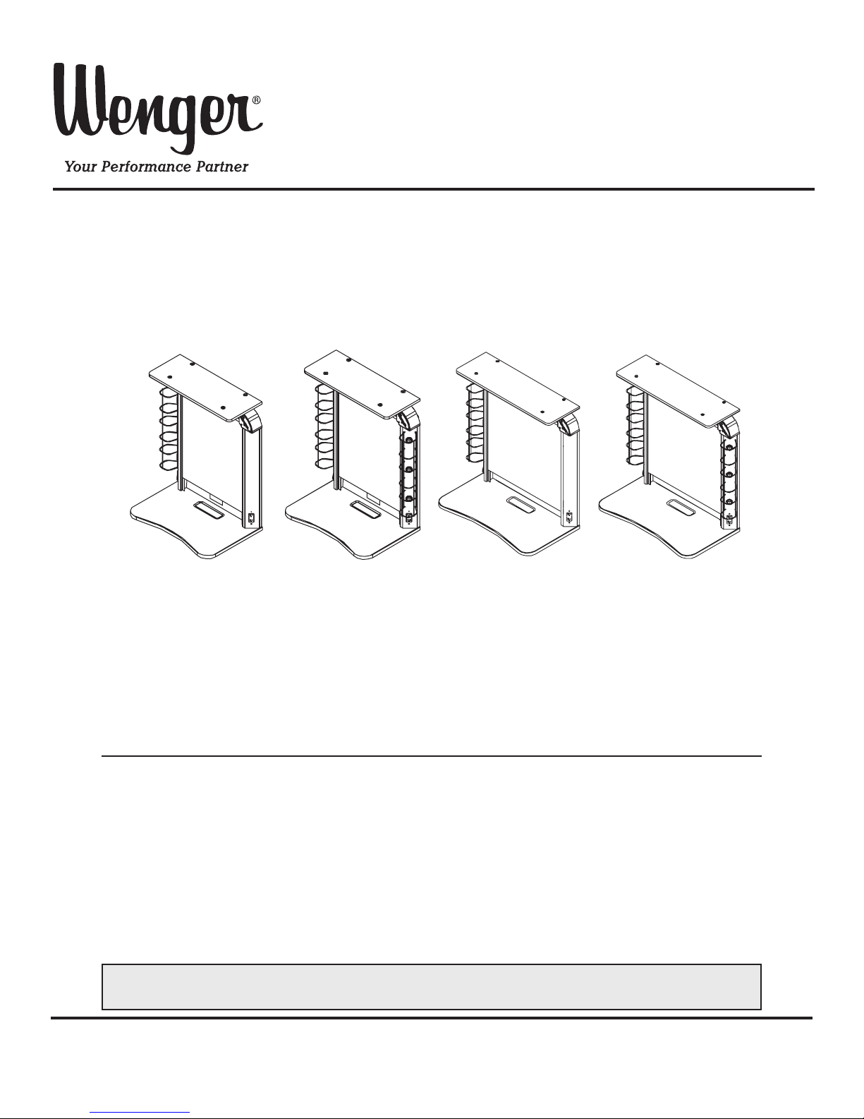
Studio®Makeup Station
30" and 36" Models
©Wenger Corporation 2018 Printed in USA 2018-03 Part #187A200-06
Wenger Corporation, 555 Park Drive, P.O. Box 448, Owatonna, Minnesota 55060-0448
Questions? Call.....USA: (800) 4WENGER (493-6437) • Worldwide: +1(507) 455-4100 • www.wengercorp.com
Contents
Important User Information . . . . . . . . . . . . . . . . . . . . . . . . . . .2
General ......................................2
Manufacturer ..................................2
Intended Use..................................2
Warranty .....................................2
Safety Precautions . . . . . . . . . . . . . . . . . . . . . . . . . . . . . . . . .3
Required Tools. . . . . . . . . . . . . . . . . . . . . . . . . . . . . . . . . . . . .3
Parts List . . . . . . . . . . . . . . . . . . . . . . . . . . . . . . . . . . . . . . . . .4
Fasteners - Not Supplied . . . . . . . . . . . . . . . . . . . . . . . . . . . .4
Before Installation . . . . . . . . . . . . . . . . . . . . . . . . . . . . . . . . . .5
Before Starting Assembly ........................5
Lighting ......................................6
Layout the Space ..............................6
Installation . . . . . . . . . . . . . . . . . . . . . . . . . . . . . . . . . . . . . . . .8
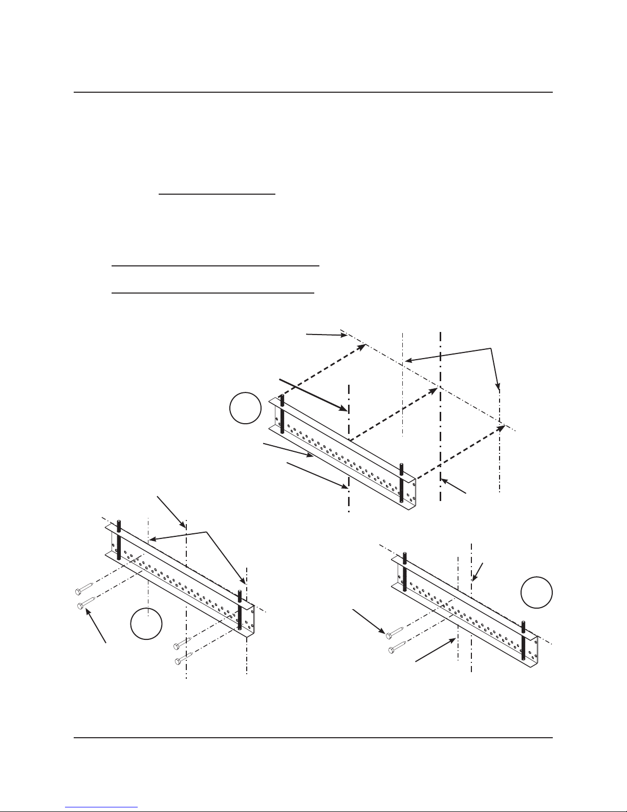
Install Mounting Bracket .........................8
Install First Makeup Station.......................10
Install Additional Makeup Stations .................14
Complete The Installation ........................14
Attach The Mirror ..............................15
Attach The Counter .............................15
Connect The Electrical Source ....................16
Tackboard Installation ...........................16
Note: Please read and understand these instructions before assembling.
Note: If you need additional information, contact Wenger Corporation using the information below.
9-light 36" Studio Makeup
Station
6-light 36" Studio
Makeup Station
8-light 30" Studio
Makeup Station
5-light 30" Studio
Makeup Station