3
EPLACE THE MAIN STAGE SHEETS NEXT
1. Locate the Handicap Lift on the unit. Remove the handicap lift enclosure by removing the
nine screws at the hinges of the enclosure. Set this enclosure aside.
2. Remove the four 3/8 x 2-1/2” lift mounting screws from the bottom of the lift.
3. Remove the four self-tapping screws from the top lift supports.
4. Disconnect the battery cable.
Locate the #2 power cable on the underside of the stage.
ove to the middle of the chassis and cut this cable in two.
WARNING: Disconnec he ba ery before working wi h any power cables.
5. easure the distance from the back wall to the far edge of the lift framework and from the
upright column to the door jam. Record these dimensions for later reassembly of the lift.
6. Slide the lift unit out onto the stage extension area, out of the way.
7. If you have a Handicap Lift, locate the two sheets that have cutouts for the lift framework.
You will begin with these sheets.
8. Locate the two sheets under the lift. One of these will be 48” wide, and the other will be
about 45-3/4” wide.
a. Remove screws from the underside of the 45-3/4” wide sheet.
b. Remove the sheet from the unit.
c. Clean the old adhesive from the steel framework.
d. If the sheet includes a tie-down ring, remove it and set it aside.
e. Clean any dirt and debris from cracks in the framework.
f. Set the replacement 45-3/4” wide sheet in place, with the cutouts located the same as the
sheet that was taken out. Slide the sheet up against the hinge on the roadside of the unit.
Sight along the edge of the sheet to align the edge with the corresponding edge on the
stage extension sheet.
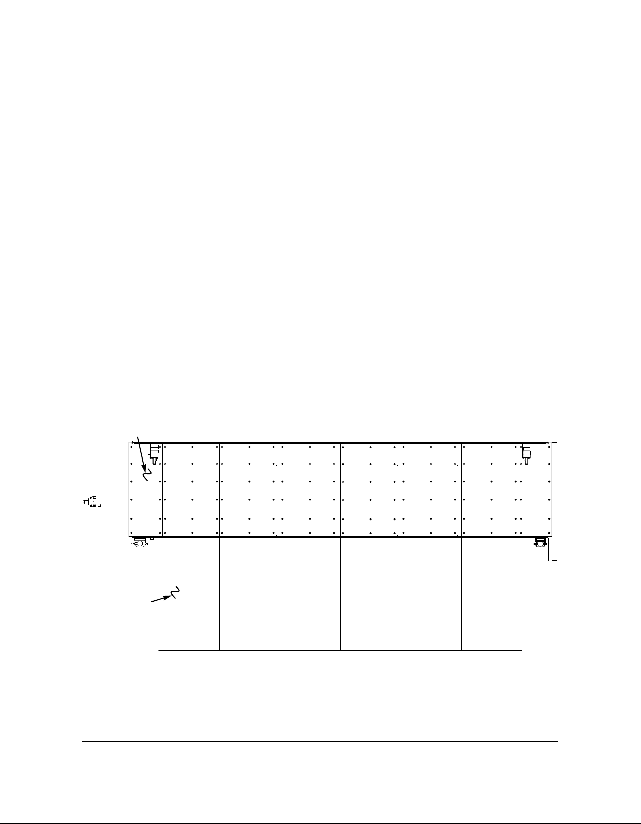
g. Drill and apply rivets 12” on center from the topside through all of the holes.
Refer to the illustration.
9. Locate the 48” sheets under the lift.
a. Remove screws from the underside of this sheet.
b. Remove the sheet from the unit.
c. Clean the old adhesive from the steel framework.
d. If the sheet includes a tie-down ring, remove it and set it aside.
e. Clean any dirt and debris from cracks in the framework.
f. Set the replacement 48” wide sheet in place, with the cutouts located the same as the
sheet that was taken out. Slide the sheet up against the hinge on the roadside of the unit.
Shim this sheet 1/16” away from the previous new sheet using the shims provided.
g. Drill and apply rivets 12” on center from the topside through all of the holes.
Refer to the illustration.
10. Repeat steps 8 and 9 for the next three sheets, but shim each sheet away from the previous
one using the 1/16” shims provided.
11. Repeat step 9 for the small sheets in the front and back of the unit.