E1DT E1DT-ASSY-0058 Owner's manual

E1DT
E1/PRI Splitter/Buffer
Copyright © 2005-2010 Somerdata Ltd.
INSTALLATION AND OPERATION
Applicable Products
E1DT - E1/PRI Splitter / Buffer
Part Numbers: E1DT-ASSY-0058
E1DT-ASSY-0059
Document Reference
E1DT-MAN-P112, Issue 4
Publication Date
31 October 2010
Published by
Somerdata Ltd.
1 Riverside Business Park
St Annes Road
Bristol
BS4 4ED
UK
Sales & Customer Support
Phone: +44 (0)1179-634050
Fax: +44 (0)1173 -302929
E-Mail: [email protected]m
support@somerdata.com
Website: www.somerdata.com

E1DT E1/PRI Splitter/Buffer
Installation and Operation
REVISION HISTORY
Issue
Date
Notes
4
Oct 2010
Contact details amended
3
21 Nov 2008
Updated
2
13 Feb 2008
Updated
1
2 Mar 2006
First Published

E1DT E1/PRI Splitter/Buffer
Installation and Operation
CONTENTS
1. INTRODUCTION 1-1
14BSCOPE 1-1
16BUSER GUIDES 1-1
2. PRODUCT DESCRIPTION 2-1
INTRODUCTION 2-1
AVAILABLE VERSIONS 2-2
E1DT-ASSY-0058 2-2
E1DT-ASSY-0059 2-2
3. POWER CONNECTION 3-1
POWER SOURCE 3-1
4. E1DT-ASSY-0058 SIGNAL CONNECTIONS 4-1
INTRODUCTION 4-1
INPUT/OUTPUT CONNECTOR PINOUTS 4-2
5. E1DT-ASSY-0059 SIGNAL CONNECTIONS 5-1
INTRODUCTION 5-1
INPUT/OUTPUT CONNECTOR PINOUTS 5-2
6. SPECIFICATIONS 6-1
LINE INTERFACE 6-3
SIGNAL 6-3
LINE CODE 6-3
DATA TYPE 6-3
SIGNAL AMPLITUDE 6-3
LINE CONNECTION 6-3
UN-POWERED PERFORMANCE 6-3
BUFFER 6-4
MONITOR OUTPUTS (STREAM AAND STREAM B) 6-4
INPUT IMPEDANCE 6-4
MONITOR OUTPUT IMPEDANCE 6-4
MONITOR OUTPUT LEVEL 6-4
MONITOR OUTPUT SIGNAL PRESENCE INDICATORS 6-4

E1DT E1/PRI Splitter/Buffer
Installation and Operation
MONITOR OUTPUT ISOLATION 6-4
INSERTION LOSS 6-4
OUTPUT TO INPUT GAIN VARIATION 6-4
OUTPUT BALANCE ERROR 6-4
NOISE (NO SIGNAL,LOADED INPUT) 6-4
CROSSTALK (STANDARD INPUT) 6-4
MAXIMUM INPUT VOLTAGE 6-4
OUTPUT DRIVE CAPABILITY 6-5
OUTPUT DRIVE ATTENUATION 6-5
UN-POWERED PERFORMANCE 6-5
CROSSTALK 6-5
RESIDUAL OUTPUT 6-5
INPUT SIGNAL LOADING 6-5
POWER REQUIREMENTS 6-5
VOLTAGE 6-5
CURRENT 6-5
CONNECTOR 6-5
POWER-ON INDICATION 6-5
ACADAPTERS 6-5
ENVIRONMENTAL 6-6
TEMPERATURE 6-6
RELATIVE HUMIDITY 6-6
PHYSICAL 6-6
DIMENSIONS 6-6
WEIGHT 6-6
7. 5BSUPPORT 7-1
47BWHAT TO DO IF YOU HAVE A PROBLEM 7-1
48BSERVICING,MAINTENANCE AND REPAIRS 7-1
49BIF YOU NEED SUPPORT 7-2
50BSOMERDATA CONTACT INFORMATION 7-2
51BSUPPORT REQUESTS 7-3
52BRETURNS 7-4
53BEND-OF-LIFE DISPOSAL 7-5
54BWASTE OF ELECTRICAL &ELECTRONIC EQUIPMENT (WEEE) 7-5

E1DT E1/PRI Splitter/Buffer
Installation and Operation
8. 6BWARRANTY 8-1
55BINTRODUCTION 8-1
56BWARRANTY:TERMS AND CONDITIONS 8-2
9. 8BNOTICES 9-1
55BGENERAL INFORMATION 9-1
DECLARATION OF CONFORMITY 9-2
SOMERDATA AND THE ENVIRONMENT 9-3
69BINTRODUCTION 9-3
70BCURRENT COMPLIANCE ACTIVITIES 9-3
71BRESTRICTION OF USE OF HAZARDOUS SUBSTANCES (ROHS) 9-4
10. INDEX 10-1

E1DT E1/PRI Splitter/Buffer
Installation and Operation
This page intentionally blank

E1DT E1/PRI Splitter/Buffer
Installation and Operation 1-1
1. INTRODUCTION
In this Section
14BSCOPE 1-1
16BUSER GUIDES 1-1
14BScope
This User Guide covers SomerData E1DT E1/PRI
Splitter/Buffer.
16BUser Guides
Printed copies can be supplied on request. Please contact
your local supplier or SomerData for ordering details.
Electronic copies (Adobe Acrobat files) are included on the
SomerData CD-ROM that is supplied with the original
products.
Additional and updated copies of the CD-ROM can be
supplied on request. Please contact your local supplier or
SomerData for ordering details.

E1DT E1/PRI Splitter/Buffer
Installation and Operation 1-2
This page intentionally blank

E1DT E1/PRI Splitter/Buffer
Installation and Operation 2-1
2. PRODUCT DESCRIPTION
In this Section
INTRODUCTION 2-1
AVAILABLE VERSIONS 2-2
Introduction
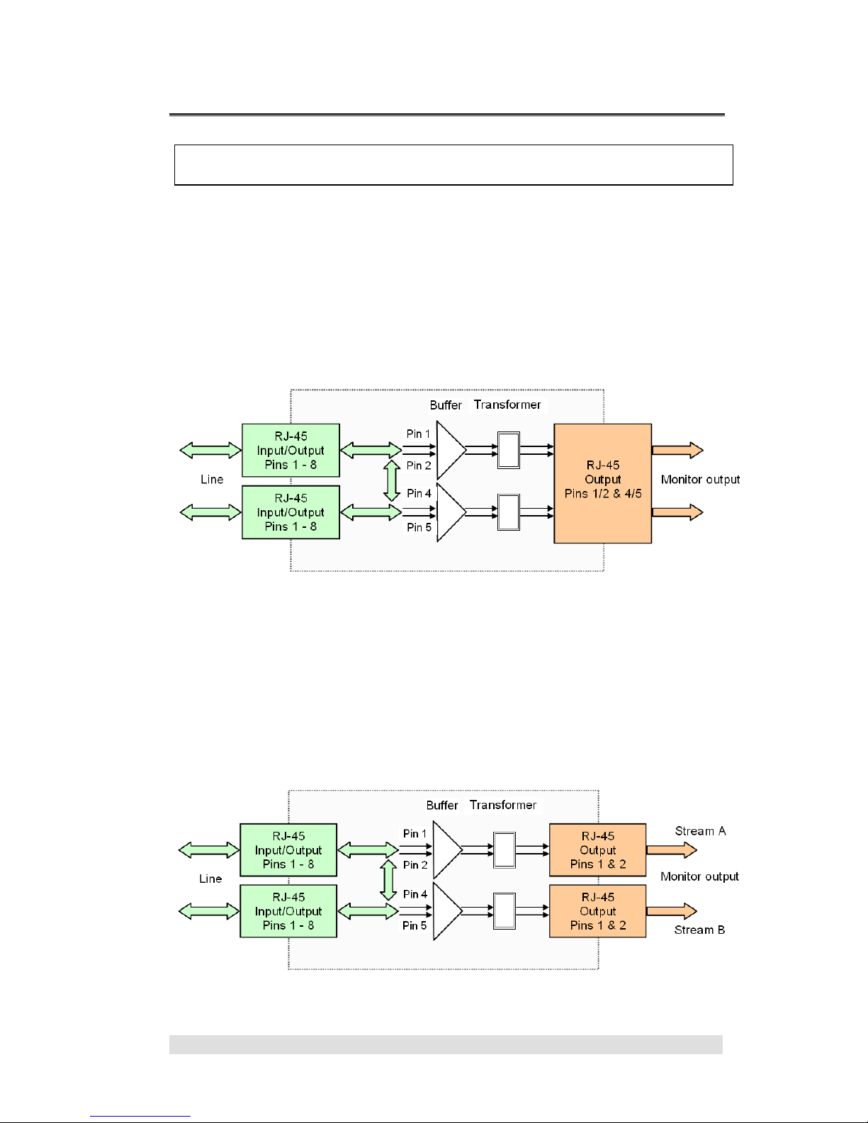
E1DT E1 Splitter/Buffer provides a means of monitoring and
capturing traffic flowing in both directions of a 2Mbits/s E1/PRI
(G.703/G.704) communications link.
The line connections are made through two RJ-45 connectors
that are hard-wired in parallel. All line activity is passed-
through the Splitter/Buffer. Monitoring and recording
equipment can be connected or disconnected without
disturbing the line.
Line signals are split and fed into high-impedance buffers that
load the line signals by less than 0.1dB. Low-impedance
outputs allow the monitoring equipment to be located up to
50m away from the line connection.
The design ensures that there is no interruption of the line
signals when the Splitter/Buffer is unpowered.
LED indicators are provided for power (green) and signal
(amber) presence at each monitor output connector.
E1DT operates from +6v to +12V DC power. UK and
European AC power adapters are available as options.

E1DT E1/PRI Splitter/Buffer
Installation and Operation 2-2
Available Versions
Two versions of E1DT are available.
E1DT-ASSY-0058
Provides the monitor outputs on a single RJ-45 connector
(Stream A pins 1/2 and 4/5) for use with devices that
monitor both Tx and RX on the same input connector.
This version is not compatible with SomerData PC-VDR
E1/PRI Recorders and R2D3 Data Capture Cards.
E1DT-ASSY-0059
Provides the monitor outputs on two RJ-45 connectors
(pins 1 & 2) for use with devices that monitor Tx and RX on
two input connectors.
This version is compatible with SomerData PC-VDR
E1/PRI Recorders and R2D3 Data Capture Cards.

E1DT E1/PRI Splitter/Buffer
Installation and Operation 3-1
3. POWER CONNECTION
In this Section
POWER SOURCE 3-1
Power Source
Recommended power source is a standard 6V, 9V or 12V
regulated 100mA power supply with 2.1 mm (centre positive) low
voltage connector.
An unregulated power supply can be used provided that the input
voltage to E1DT does not exceed 12V.
UK and European AC power adapters are available as options.
+6 Volts DC to +12 Volts DC
0 Volts

E1DT E1/PRI Splitter/Buffer
Installation and Operation 3-2
This page intentionally blank

E1DT E1/PRI Splitter/Buffer
Installation and Operation 4-1
4. E1DT-ASSY-0058 SIGNAL CONNECTIONS
In this Section
INTRODUCTION 4-1
INPUT/OUTPUT CONNECTOR PINOUTS 4-2
Introduction
Both Tx and Rx monitor outputs are on a single RJ-45 connector
(Stream A).
E1DT-ASSY-0058 should not be used with a SomerData PC-VDR
E1/PRI Recorder or R2D3 E1/PRI Data Capture Card
(see E1DT-ASSY-0059).
Connections should be made using standard CAT5 (1:1) cable.

E1DT E1/PRI Splitter/Buffer
Installation and Operation 4-2
Input/Output Connector Pinouts
.
This product is not approved for connection to public
telecommunications systems. It is the User’s responsibility to ensure
that this equipment is used in compliance with appropriate legislation
relating to connection with telecommunications networks.
Monitor Outputs
Pin
Stream A
1
Output +ve
Tx direction
2
Output -ve
3
Ground
4
Output +ve
RX direction
5
Output -ve
6
Not used
7
Not used
8
Not used
Line Input/Output
Pin Pin
1 –1
2 –2
3 –3
4 –4
5 –5
6 –6
7 –7
8 –8

E1DT E1/PRI Splitter/Buffer
Installation and Operation 5-1
5. E1DT-ASSY-0059 SIGNAL CONNECTIONS
In this Section
INTRODUCTION 5-1
INPUT/OUTPUT CONNECTOR PINOUTS 5-2
Introduction
Tx and Rx monitor outputs are on two RJ-45 connectors.
Stream A for the Line Tx bitstream and Steam B for the Line Rx
bitstream.
Both bitstreams appear on the Tx pins of the monitor output
connectors for compatibility with with SomerData PC-VDR E1/PRI
Recorders and R2D3 E1/PRI Data Capture Cards.
Connections should be made using standard CAT5 (1:1) cable.

E1DT E1/PRI Splitter/Buffer
Installation and Operation 5-2
Input/Output Connector Pinouts
Monitor Outputs
Pin
Stream A
Stream B
1
Output +ve
Output +ve
2
Output -ve
Output -ve
3
Ground
Ground
4
Not used
Not used
5
Not used
Not used
6
Not used
Not used
7
Not used
Not used
8
Not used
Not used
Line Input/Output
Pin Pin
1 –1
2 –2
3 –3
4 –4
5 –5
6 –6
7 –7
8 –8

E1DT E1/PRI Splitter/Buffer
Installation and Operation 6-1
6. SPECIFICATIONS
In this Section
LINE INTERFACE 6-3
SIGNAL 6-3
LINE CODE 6-3
DATA TYPE 6-3
SIGNAL AMPLITUDE 6-3
LINE CONNECTION 6-3
UN-POWERED PERFORMANCE 6-3
Crosstalk 6-3
Residual output 6-3
Input signal loading 6-3
BUFFER 6-4
MONITOR OUTPUTS (STREAM AAND STREAM B) 6-4
E1DT-ASSY-0058 6-4
E1DT-ASSY-0059 6-4
INPUT IMPEDANCE 6-4
MONITOR OUTPUT IMPEDANCE 6-4
MONITOR OUTPUT LEVEL 6-4
MONITOR OUTPUT SIGNAL PRESENCE INDICATORS 6-4
MONITOR OUTPUT ISOLATION 6-4
INSERTION LOSS 6-4
OUTPUT TO INPUT GAIN VARIATION 6-4
OUTPUT BALANCE ERROR 6-4
NOISE (NO SIGNAL,LOADED INPUT) 6-4
CROSSTALK (STANDARD INPUT) 6-4
MAXIMUM INPUT VOLTAGE 6-4
OUTPUT DRIVE CAPABILITY 6-5
OUTPUT DRIVE ATTENUATION 6-5
UN-POWERED PERFORMANCE 6-5
CROSSTALK 6-5
RESIDUAL OUTPUT 6-5
INPUT SIGNAL LOADING 6-5

E1DT E1/PRI Splitter/Buffer
Installation and Operation 6-2
POWER REQUIREMENTS 6-5
VOLTAGE 6-5
CURRENT 6-5
CONNECTOR 6-5
POWER-ON INDICATION 6-5
ACADAPTERS 6-5
ENVIRONMENTAL 6-6
TEMPERATURE 6-6
RELATIVE HUMIDITY 6-6
PHYSICAL 6-6
DIMENSIONS 6-6
WEIGHT 6-6

E1DT E1/PRI Splitter/Buffer
Installation and Operation 6-3
Line Interface
Signal
ITU G.703/G.704, 2,048 kbits/s
Line Code
HDB3
Data Type
Framed or Unframed
Signal Amplitude
Operating: ±3.00V ±10% nominal
Absolute Maximum: -5V (lower limit)
+5V (upper limit)
Line Connection
Two RJ-45 connectors hard-wired in parallel.
Optional BNC adapter cable available on request.
Line connection supports 120 balanced, 75 unbalanced
or monitor connection.
Note that there are no terminating devices in the line
interface.
Un-powered performance
Applies to the pass-though connection
Crosstalk
Better than -64dB
Residual output
Better than -35dB
Input signal loading
Less than 0.1dB

E1DT E1/PRI Splitter/Buffer
Installation and Operation 6-4
Buffer
Monitor Outputs (Stream A and Stream B)
E1DT-ASSY-0058
RJ-45 connector (Tx pins 1/2 and Rx pins 4/5)
E1DT-ASSY-0059
Two RJ-45 connectors (Tx pins 1/2) compatible with
SomerData R2D3 E1/PRI Data Capture card
Input Impedance
1500
Monitor Output Impedance
120 balanced
Monitor Output Level
Unloaded: 2 x Input Level
Loaded: Unity Gain
Monitor Output Signal Presence Indicators
LED indicator
±1.2V p-p signal detection threshold
Monitor Output Isolation
Transformer coupled
1500V RMS AC breakdown
Insertion Loss
Less than 0.2dB
Output to Input Gain Variation
Less than 0.1dB
Output Balance Error
-70db (typical)
Noise (no signal, loaded input)
Better than -63dB
Crosstalk (standard input)
Better than -47dB
Maximum Input Voltage
±3.5V
This manual suits for next models
1
Table of contents
Popular Cables And Connectors manuals by other brands

Tyco Electronics
Tyco Electronics ACO Single Port Kits instruction sheet

3M
3M 7700 Series Preparation Instructions

Philips
Philips SWV2516W Specifications

Philips
Philips SWA2110NB Specifications

BrassCraft
BrassCraft Safety+PLUS ADVANTAGE Installation instructions manual

Axxess
Axxess AX-ADVW01 installation instructions