Werner T100009 User manual
Werner Co. Fall Protection 724-588-2000
93 Werner Rd. 888-523-3371 toll free
Greenville, PA 16125 888-456-8458 fax
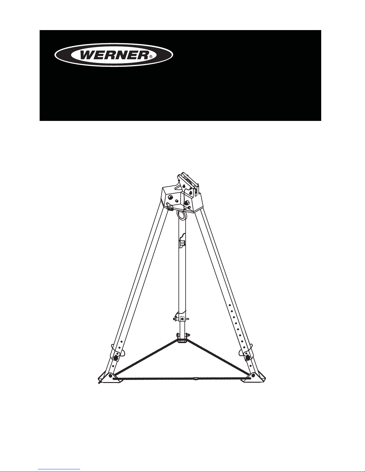
TRIPOD SYSTEM
Complies with ANSI Z359.1, ANSI Z359.4 standards and OSHA 29 CFR 1910
and 1926 regulations.
FALL PROTECTION
USER INSTRUCTIONS
Models: T100009, T210030B, T210060B, T210100B, T510000B, T510045,
T510000, T200001

Page 2
ENGLISH
WARNING!
Compliant fall protection equipment must only be used as it was designed.
Users MUST read and follow all user instructions provided with the product.
Before using a fall arrest system, users must be trained in the safe use of
the system, as required by OSHA 29 CFR 1910.30 and 1926.503, or local
safety regulations. Misuse or failure to follow these warnings and
instructions may result in injury or even death.
WORK SAFE! WORK SMART!
IF YOU HAVE ANY QUESTIONS ABOUT THE PROPER USE OF THE EQUIPMENT,
SEE YOUR SUPERVISOR, USER INSTRUCTIONS, OR CONTACT WERNER CO.
FOR MORE INFORMATION.
WARNING!
All components of the Tripod System must be inspected prior to each use in
accordance with the requirements of OSHA 29 CFR 1910.140 and 1926.502.
The Tripod System is designed for up to two users at one time for emergency
rescue applications only.
Do not use the Tripod without the safety chain, or without safety chain
properly adjusted.
Shoulder D-rings of the full body harness are for rescue and entry/retrieval
applications only. Always use both shoulder D-rings together simultaneously.
Never use combinations of components or subsystems that may affect, or
interfere with, the safe function of each other.
If inspection reveals any defect, inadequate maintenance, or unsafe
condition, remove from service until a “competent”person, as dened by
OSHA 29 CFR 1926.32(f), can determine the need for authorized repair or
disposal.
Any equipment that has been subjected to the forces of arresting a fall,
or that has a deployed load indicator, must be removed from service until
a “competent person” can determine the need for authorized repair or
disposal.
WARNING!

TRIPOD SYSTEM
USER INSTRUCTIONS
Page 3
ENGLISH
USE INSTRUCTIONS AND LIMITATIONS
IMPORTANT
Before use, the user must read and understand these User Instructions. Keep
these User Instructions for reference.
PURPOSE
The Tripod System is designed to be used as part of a personal fall arrest,
rescue, work positioning, or material handling system.
USE INSTRUCTIONS
1. Failure to follow all instructions and limitations on the use of the Tripod
System may result in serious personal injury or death.
2. Before using a personal fall arrest system, employees must be trained in
accordance with the requirements of OSHA 29 CFR 1910.30 in the safe use
of the system and its components.
3. Personal fall arrest systems, including the Tripod System, must be inspected
prior to each use for wear, damage, and other deterioration. Defective
components must be immediately removed from service, in accordance with
the requirements of OSHA 29 CFR 1910.140 and 1926.502.
4. The complete fall protection system must be planned (including all
components, calculating fall clearance, and swing fall) before using.
5. Users must have a rescue plan, and the means to implement it, that provides
for the prompt rescue of employees in the event of a fall, or assures that
employees are able to rescue themselves.
6. Store the Tripod System in a cool, dry, clean environment and out of direct
sunlight when not in use.
7. After a fall occurs on the system, immediately remove from service until a
“competent person” can make the determination for reuse or disposal.
USE LIMITATIONS
1. CAPACITY: The Tripod System is designed for a single user only, and is
designed for two users at one time only for emergency rescue applications,
with a capacity (including clothing, tools, etc.) up to 310 pounds (140 kg)
total working weight per user, in conjunction with compatible connecting
components.
2. EXTENDED SUSPENSION: The Tripod System is designed for use in
extended suspension applications.
3. CORROSION: Do not leave the Tripod System in environments where
corrosion of metal parts could take place as a result of vapors from organic
materials. Use near seawater or other corrosive environments may require
more frequent inspections to ensure corrosion damage is not affecting the
performance of the product.

Page 4
ENGLISH
4. CHEMICAL HAZARDS: Solutions containing acids, alkali, or other caustic
chemicals, especially at elevated temperatures, may cause damage to the
Tripod System. When working with such chemicals, frequent inspection of
this equipment must be performed. Contact Werner Co. with any questions
concerning the use of the Tripod System around chemical hazards.
5. EXTREME TEMPERATURE: The Tripod System is designed to be used in
temperatures ranging from -40ºF to +130ºF (-40°C to +54°C). Protection
should be provided for Tripod System when used near welding, metal cutting
or similar activities. Contact Werner Co. with any questions concerning high
temperature environments.
6. ELECTRICAL HAZARDS: Use extreme caution when working near high
voltage power lines due to the possibility of electric current owing through
the Tripod System or connecting components.
7. ANCHORAGES: The anchorage must be capable of supporting loads
applied in all directions permitted by the system of 5,000 pounds (22.2 kN),
or twice the maximum arrest load.
8. COMPONENT COMPATIBILITY: Only components approved by Werner Co.
may be used with the Tripod System.
9. SYSTEMS: Only one personal fall arrest system may be in use on the Tripod
System. A maximum of two systems (retrieval and fall arrest) may be in use
at the same time on the Tripod. Only one system may be attached to any one
Tripod leg.
10. SUBSYSTEMS: Only connecting subsystems that limit the maximum arrest
force to less than 1,800 pounds (8 kN) may be used with the Tripod System.
11. HEALTH: Minors, pregnant women and anyone with a history of either back
or neck problems should not use this equipment.
12. TRAINING: Do not use or install the Tripod System without proper training
from a “competent person” per OSHA 29 CFR 1926.503 or a "qualied
person" per OSHA 29 CFR 1910.30.
13. REPAIRS: Only Werner Co., or persons or entities authorized in writing by
Werner Co., may make repairs or alterations to the equipment.
ANCHORAGE REQUIREMENTS
ANCHORAGES
All anchorages on which the Tripod System mounts must meet the requirements
of ANSI Z359.1-2007 and OSHA 29 CFR 1910.140 and 1926.502.

TRIPOD SYSTEM
USER INSTRUCTIONS
Page 5
ENGLISH
OSHA states:
Anchorages used for attachment of personal fall arrest equipment shall be
independent of any anchorage being used to support or suspend platforms
and capable of supporting at least 5,000 pounds (22.2 kN) per employee
attached, or shall be designed, installed, and used as part of a complete
personal fall arrest system which maintains a safety factor of at least two;
and under the supervision of a qualied person.
ANSI Z359.1-2007 states that anchorages in a personal fall arrest system must
have a strength capable of sustaining static loads, applied in all permitted
directions by the system, of at least:
(a) two times the maximum arrest force permitted on the system when
certication exists, or
(b) 5,000 pounds (22.2 kN) in the absence of certication
The strength in (a) and (b) must be multiplied by the number of personal fall
arrest systems attached to the anchorage, when more than one personal fall
arrest system is attached to the anchorage.
Anchorages used in work positioning systems must be capable of supporting
loads of 3,000 pounds (13.3 kN) for non-certied anchorages or two times the
foreseeable force for certied anchorages per ANSI Z359.2-2007.
Anchorages used in rescue and controlled descent systems must be capable of
supporting loads of 3,100 pounds (13.8 kN) for non-certied anchorages or a 5:1
safety factor for certied anchorages per ANSI Z359.4-2007.
ANCHORAGE CONNECTORS
Anchorage connectors function as an interface between the anchorage and
the personal fall arrest system, for the purpose of coupling the system to the
anchorage. The Tripod is the anchorage connector and is designed to meet
a 5,000 pound tensile load when statically tested in accordance with the
requirements of the ANSI Z359.1-2007 standard.
CONNECTION REQUIREMENTS
COMPATIBILITY LIMITATIONS
All connecting subsystems must only be coupled to compatible connectors.
OSHA 29 CFR 1926.502 prohibits snap hooks from being engaged to certain
objects unless two requirements are met: snap hook must be a locking type
and must be "designed for" making such a connection. Under OSHA 29
CFR 1926.502 "designed for" means that the manufacturer of the snap hook
Page 6
ENGLISH
specically designed the snap hook to be used to connect to the equipment in
question.
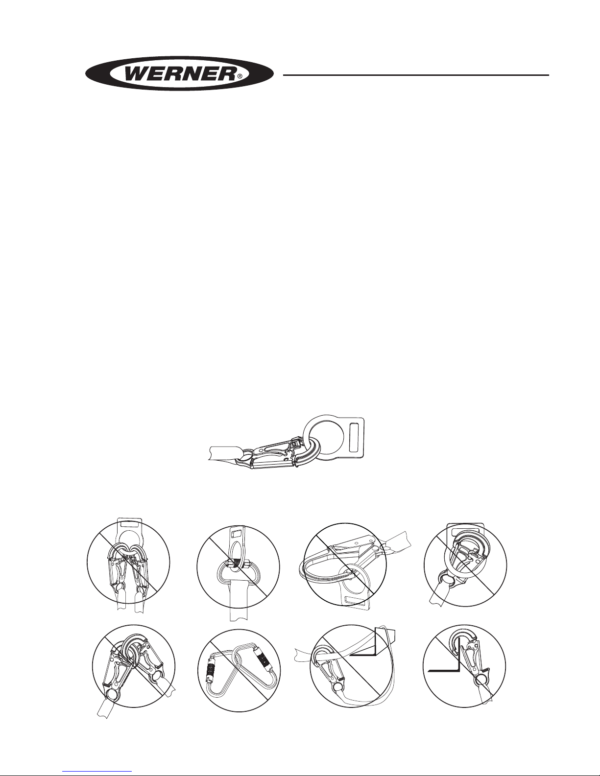
The following connections must be avoided, because they can result in rollout*
when a non locking snap hook is used:
• Direct connection of a snap hook to horizontal lifeline.
• Two (or more) snap hooks connected to one D-ring.
• Two snap hooks connected to each other.
• A snap hook connected back on its integral lanyard.
• A snap hook connected to a webbing loop or webbing lanyard.
• Improper dimensions of the D-ring, rebar, or other connection point in
relation to the snap hook dimensions that would allow the snap hook
keeper to be depressed by a turning motion of the snap hook.
*Rollout: A process by which a snap hook or carabiner unintentionally
disengages from another connector or object to which it is coupled. (ANSI
Z359.0)
COMPATIBLE CONNECTIONS
INCOMPATIBLE CONNECTIONS
NO! NO! NO! NO!
NO!NO!NO!NO!

TRIPOD SYSTEM
USER INSTRUCTIONS
Page 7
ENGLISH
SNAP HOOKS AND CARABINERS
Snap hooks and carabiners used in the Tripod System, marked with the ANSI
Z359.1-07 or ANSI Z359.12-09 standard, are self-locking with a minimum tensile
break strength of 5,000 pounds (22.2 kN), and a 3,600 pound (16 kN) gate rating.
SYSTEM COMPONENTS
COMPATIBILITY LIMITATIONS
All components and subsystems used with the Tripod System have been tested
as part of a complete fall arrest system. Only components and subsystems
approved by Werner Co. are to be used with the Tripod System.
ANCHORAGE CONNECTORS
TRIPOD: T100009
The high strength aluminum Tripod extends from 70 inches (1.7 m) to 84 inches
(2.1 m) for installation over openings with a maximum diameter of 72 inches
(1.8 m) at lowest height to a diameter up to 80 inches (2.0 m) at tallest height.
The head of the Tripod includes two ⅝inch forged steel eye bolts. The eye bolts
are for ANSI Z359.1-07 and ANSI Z359.4-07 direct connection of fall arrest and
rescue subsystems.
The aluminum feet have rubber skid pads and a safety chain to help prevent the
legs from spreading apart.
SRL-R MOUNTING BRACKET: T210030B, T210060B,
T210100B
The steel Mounting Bracket attaches to any leg of the tripod. The T210030B is
designed to t the T210030 3-Way Self Retracting Lifeline with Rescue Capability
(SRL-R), the T210060B is designed to t the T210060 SRL-R and the T210100B
is designed to t the T210100 SRL-R.
MATERIAL HOIST MOUNTING BRACKET:T510000B
The steel Mounting Bracket attaches to any leg of the tripod. The T510000B is
designed to t the T510045 Hoist.
PULLEY:T200001
The aluminium alloy Pulley is designed for use with up to a 7⁄16 inch (12 mm)
diameter steel cable. The Pulley has a 8,100 pound (36 kN) tensile breaking
strength.
Page 8
ENGLISH
CONNECTING DEVICES
3-WAY SELF RETRACTING LIFELINE WITH RESCUE CAPABILITY:
T210030, T210060, T210100
The 3-Way Self Retracting Lifeline with Rescue Capability (SRL-R) are designed
for a single user with a capacity up to 310 pounds (140 kg) including clothing,
tools, etc, and comes in 30 feet (T210030), 60 feet (T210060) and 100 feet
(T210100) lengths. The 3-Way SRL-Rs have a polymer housing, and utilize a 3⁄16
inch (4.8 mm) diameter (7x19) galvanized steel cable. When dynamically tested in
accordance with the requirements of the ANSI Z359.14 standard for Class B for
SRLs, the 3-Way SRL-Rs have an average arrest force of less then 900 pounds
(4 kN) and a maximum arrest distance of 54 inches (1372 mm).
MATERIAL HOIST: T510045
The Material Hoist is capable of raising and lowering loads of 450 pounds and
has 60 feet (18 m) of 3⁄16 inch (4.8 mm) diameter (7x19) galvanized steel cable.
The Material Hoist requires the T510000B Mounting Bracket for mounting onto
the Tripod.
INSTALLATION
All components of the Tripod System must be inspected
prior to each use in accordance with the requirements of
OSHA 29 CFR 1910.140 and 1926.502.
BEFORE EACH USE
Users must have a rescue plan, and the means to implement it, that provides for
the prompt rescue of employees in the event of a fall or assures that employees
are able to rescue themselves.
The user must read and understand these user instructions, as well as the
user instructions for every component and subsystem of the personal fall arrest
system. The entire Tripod System, and its subsystems, must be inspected prior to
each use. See INSPECTION.
The Tripod System must be mounted on stable level surface for each leg and
positioned over an opening that is within the installation diameter specied on
page 7.
WARNING!

TRIPOD SYSTEM
USER INSTRUCTIONS
Page 9
ENGLISH
MULTIPLE SYSTEMS
Multiple systems may be attached to the Tripod; however, the Tripod is for a single
user only. A maximum of two systems may be attached to one Tripod, and a
maximum of one system may be attached to any one Tripod leg.
The Tripod System is designed for up to two users at one
time for emergency rescue applications only.
STEP 1: ASSEMBLE TRIPOD
Place the Tripod on the oor with the feet on the ground. Remove the locking
pins from the head of the Tripod. Pull the legs away from the center and replace
the locking pins in head to secure the legs in the open position. Extend legs
to desired length and secure in place with locking pin. Place the Tripod over
the entry point. Adjust the Tripod as necessary by removing the leg pins so the
Tripod is level above the entry point. Remove excess slack in the safety chain by
adjusting the position of the carabiner.
Do not use the Tripod without the safety chain or without
safety chain properly adjusted.
STEP 2: ATTACH SRL-R MOUNTING BRACKET (T210030B,
T210060B, T210100B)
The mounting bracket attaches to the upper leg of the Tripod. Remove two locking
pins on the bottom of the mounting bracket and place on upper leg of the Tripod
orientated so the ange of the mounting bracket is on the external right. Insert
locking pins through holes on the bottom of the mounting bracket and through
upper leg of the tripod.
STEP 3: MOUNT 3-WAY SRL-R
Loosen the large washer on the back of the 3-Way SRL-R with an allen wrench.
Orient 3-Way SRL-R so the cable is facing the top of the Tripod and the crank is
to the right. Mount 3-Way SRL-R to the right side of the mounting bracket ange.
Slide the large washer into the slot on the mounting bracket and tighten with allen
wrench. Insert hand screw through the swivel top of the 3-Way SRL-R through the
bottom of the mounting bracket and hand tighten.
WARNING!
WARNING!

Page 10
ENGLISH
STEP 3A: ATTACH THE MATERIAL HOIST
The material hoist attaches to the mounting bracket with four bolts supplied
with the mounting bracket. Insert the four bolts through the mounting bracket
and into the material hoist. Tighten in a diagonal sequence using allen wrench.
Place material hoist on the upper leg of the Tripod, orientated so the drum of the
material hoist is towards the top of the Tripod. Insert locking pins through holes on
the bottom of the mounting bracket and through upper leg of the Tripod.
STEP 4: TURN CABLE OVER PULLEY ON TOP OF TRIPOD
Remove the pin above the pulley on the top of the Tripod and feed the cable over
the pulley and through the center hole in the head of the Tripod. Replace the pin
above the pulley.
STEP 4A: TURN CABLE OVER PULLEY
Twist both sides of the T200001 Pulley open to allow insertion of cable. Insert the
cable of 3-Way SRL-R or material hoist and twist both sides to original position.
Lock both sides together by attaching the carabiner on the head of the Tripod.
CONNECTION
NUMBER OF USERS
The Tripod System is designed for a single user only, and is designed for two
users at one time only for emergency rescue applications, with a capacity
(including clothing, tools, etc.) up to 310 pounds (140 kg) total working weight per
user.
3-WAY SRL-R FOR FALL ARREST APPLICATIONS
The 3-Way SRL-R must only be connected to the dorsal D-ring of the full body
harness for a fall arrest application.
3-WAY SRL-R FOR RESCUE APPLICATIONS
The 3-Way SRL-R may be connected in multiple ways for rescue applications.
• 3-Way SRL’s connected to the dorsal D-ring of the full body harness for
fall arrest may be used for rescue.
• The 3-Way SRL-R may attach to the Class L sternal (front) D-ring of the
full body harness on a user in need of rescue. See full body harness
user instructions for more information.

TRIPOD SYSTEM
USER INSTRUCTIONS
Page 11
ENGLISH
• The 3-Way SRL-R may attach to a rescue yoke in rescue applications.
The rescue yoke connects to Class E shoulder D-rings on the full
body harness of a user in need of rescue. See full body harness user
instructions for more information.
Shoulder D-rings of the full body harness are for rescue
and entry/retrieval applications only. Always use both
shoulder D-rings together simultaneously.
3-WAY SRL-R FOR POSITIONING APPLICATIONS
3-Way SRL-R’s may attach to the D-ring of a bosun chair for positioning
applications. A separate personal fall arrest system connected to the dorsal D-ring
of the full body harness is required with the use of a bosun chair. See bosun chair
user instructions for more information.
SELF-RETRACTING LIFELINES (SRLS)
Attach the housing connector of the self-retracting lifeline to the eye bolt in the
head of the Tripod. The opposite end is connected to the dorsal D-ring of the full
body harness. Never attach an additional energy absorbing lanyard or self-
retracting lifeline to lengthen the lifeline. See user instructions supplied with
the Self Retracting Lifeline.
Never use combinations of components or subsystems
that may affect, or interfere with, the safe function of
each other.
VERTICAL LIFELINES
Attach the Vertical Lifeline to the eye bolt in the head of the Tripod. Ensure the
Vertical Lifeline hangs freely without twists or knots in the lifeline. See user
instructions supplied with the Vertical Lifeline.
WARNING!
WARNING!
Page 12
ENGLISH
INSPECTION AND MAINTENANCE
If inspection reveals any defect, inadequate
maintenance, or unsafe condition, remove from service
until a “competent person”, as dened by OSHA 29 CFR
1926.32(f), can determine the need for authorized repair
or disposal.
Proper Personal Protective Equipment must be
worn when performing Inspection and Maintenance
procedures.
FREQUENCY
All components of the Tripod System must be inspected prior to each use and
annually by an OSHA dened “competent person” other than the user. Local,
state, governmental and jurisdictional agencies governing occupational safety
may require the user to conduct more frequent or mandatory inspections.
CRITERIA
Any equipment that has been subjected to the forces
of arresting a fall, or that has a deployed load indicator,
must be removed from service until a “competent
person” can make the determination for reuse or
disposal.
All components and subsystems of the Tripod System must be inspected. See
user instructions supplied with the product for inspection criteria.
All markings must be legible and attached to the product.
WARNING!
WARNING!
CAUTION!

TRIPOD SYSTEM
USER INSTRUCTIONS
Page 13
ENGLISH
Each leg must be able to lock in place at the head of the Tripod with the locking
pin. Each leg must be straight and able to lock into place with the locking pin
when extended. The foot on each leg must pivot freely and have the rubber skid
pads attached. The head of the Tripod including the eye bolt and the safety chain
must be free of damage.
All equipment must be free of corrosion, chemical attack, alteration, excessive
heating or wear.
All snap hooks and carabiners must be able to self-close and lock. All hardware
must be free of cracks, sharp edges, deformation, corrosion, or any evidence of
defect.
CLEANING AND STORAGE
CLEANING
Cleaning maintenance may be performed by the user. The Tripod System may
be wiped down with a mild detergent and clean water solution and rinsed with
a dampened clean cloth to remove detergent. The hardware can also be wiped
down to remove grease or dirt with a clean dry cloth.
STORAGE
The Tripod System should be stored in a cool, dry place out of direct sunlight
when not in use. Do not store where damage from environmental factors such as
heat, light, excessive moisture, oil, chemicals and their vapors, or other degrading
elements may be present.
Do not store damaged equipment or equipment in need of maintenance in the
same area as product approved for use. Equipment that has been stored for an
extended period must be inspected as dened in these user instructions prior to
use.

Page 14
ENGLISH
LABELS
Standards:
ANSI Z359.1, ANSI Z359.4,
OSHA 29 CFR 1910.140 and 1926.502
Minimum Breaking
Strength (MBS):
5,000 pounds
Capacity rating:
310 pounds (140 kg) per user
Single user only.
Two users at one time for
emergency rescue
applications only.
Materials:
High Strength Aluminum
Werner Co.
93 Werner Road, Greenville, PA 16125
1-888-523-3371
www.wernerco.com
P/N113194-01 Rev A 3/17
Model: T100009
Date of Manufacture
(month/year):
Serial Lot Number:
Tripod
WARNING
User MUST read and follow all user
instructions provided with the product. See
user instructions for installation, stability and
compatibility limitations. Product must be
inspected prior to each use according to the
user instructions. Only make compatible
connections. User repairs and alterations are
NOT permitted. Avoid physical and
environmental hazards such as thermal,
electrical and chemical sources.
Misuse or failure to follow these
warnings and instructions may result
in injury or even death.
MADE IN INDIA
Inspection chart
YEAR J F M A M J J A S O N D
Insert locking pins into
holes below to adjust
the height of tripod.
113194-02
113194-03
P
/
N
1
1
3
1
9
4
-
0
2
R
e
v
A
3
/
1
7
Werner Co.
93 Werner Road
Greenville, PA 16125
1-888-523-3371
www.wernerco.com
P/N113194-03 Rev A 3/17
TRIPOD SYSTEM
USER INSTRUCTIONS
Page 15
ENGLISH
SPECIFICATION
WERNER CO. TRIPOD SYSTEM
This product meets ANSI Z359.1 and ANSI Z359.4 standards and OSHA 29 CFR
1910.140 and 1926.502 regulations for the anchorage connector component of a
complete personal fall arrest/rescue system.
Individually bar coded model and serial numbers, location and date of
manufacture are on product label.
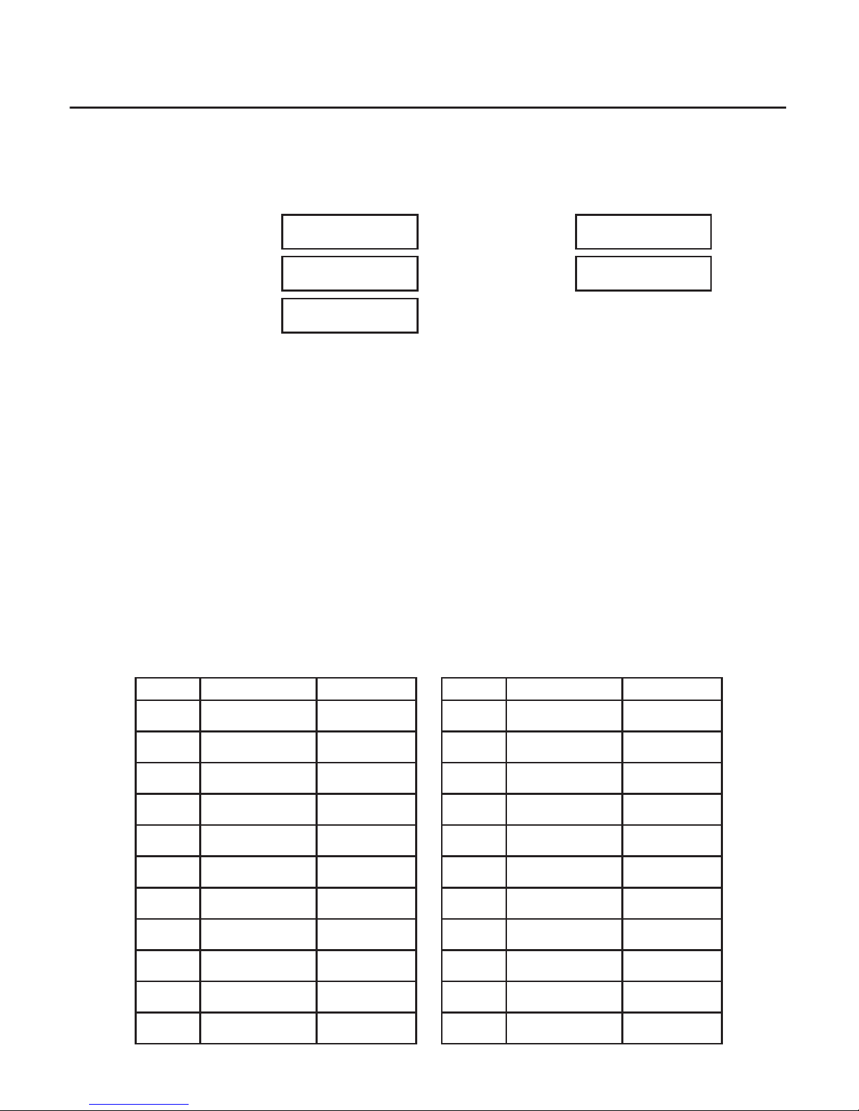
INSPECTION RECORD
MODEL NUMBER
SERIAL NUMBER
DATE
MANUFACTURED
PURCHASE DATE
ASSIGNED TO
EQUIPMENT RECORD
DATE INSPECTOR PASS/FAIL DATE INSPECTOR PASS/FAIL

PN113190-01 ©2017 Werner Co. Rev A 3/17
Werner Co. Fall Protection
93 Werner Rd. Greenville, PA 16125
724-588-2000 • 888-523-3371 toll free • 888-456-8458 fax
This manual suits for next models
7
Table of contents


