1-1 (E)
CBK-MB01
Section 1
Installation
1-1. CBK-MB01 Configuration
The CBK-MB01 consists of the following:
.MY-113 board (1)
.Precision screws P1.4 x3.5 (2)
.Installation Guide (1)
.Installation Manual (1)
In addition to the Installation Manual, the following manuals are available.
.DVW-970/970P Operation Manual (Supplied with DVW-970/970P)
This manual is necessary for application and operation of DVW-970/970P.
.CBK-MB01 Maintenance Manual
This manual intended for use by trained system and service engineers describes the information (Block
diagrams, schematic diagrams, Parts list and etc.) required for parts-level service.
For obtaining, contact your local Sony Sales Office/Service Center.
Part number: 9-968-182-0X
1-2. Installation Procedure
Outline of the installing the CBK-MB01 to the DVW-970/970P is listed as follows. For the details of the
installation work, refer to the respective sections.
n
When removing or installing the plug-in board, be careful not to damage the parts on circuit board, not to
insert the boards in the wrong slot and not to insert the boards in wrong directions.
Installation procedure Sections describing the detailed procedure
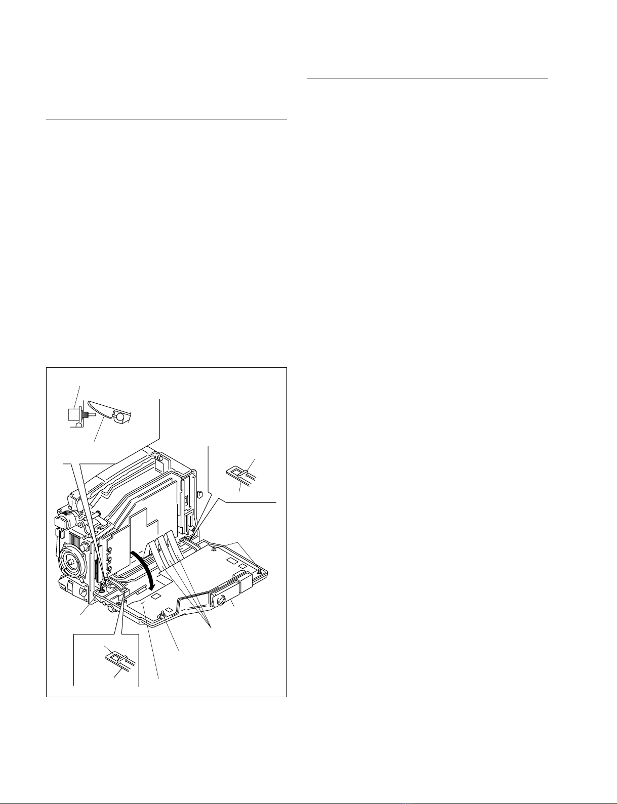
1. Opening the Inside Panel 1-3. Opening and Closing the Inside Panel Assembly
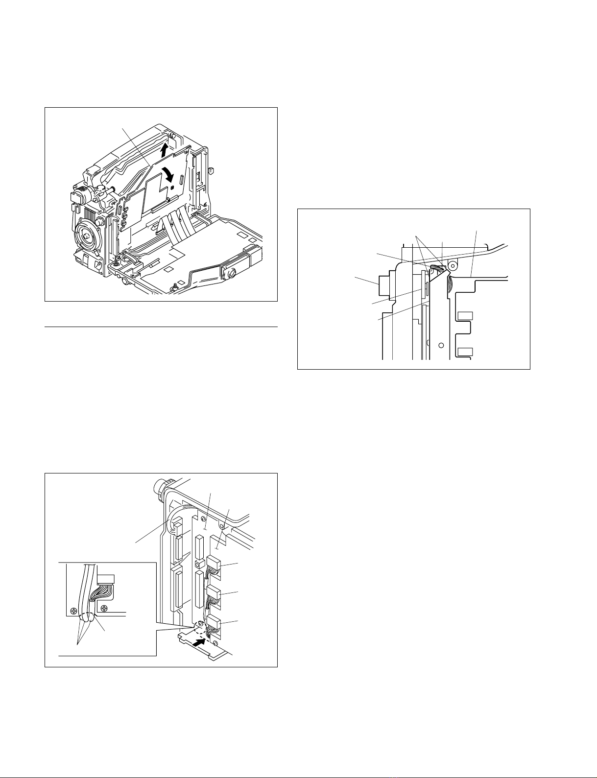
2. Removing the DCP Board Assembly 1-4. Removing and Installing the DCP Board Assembly
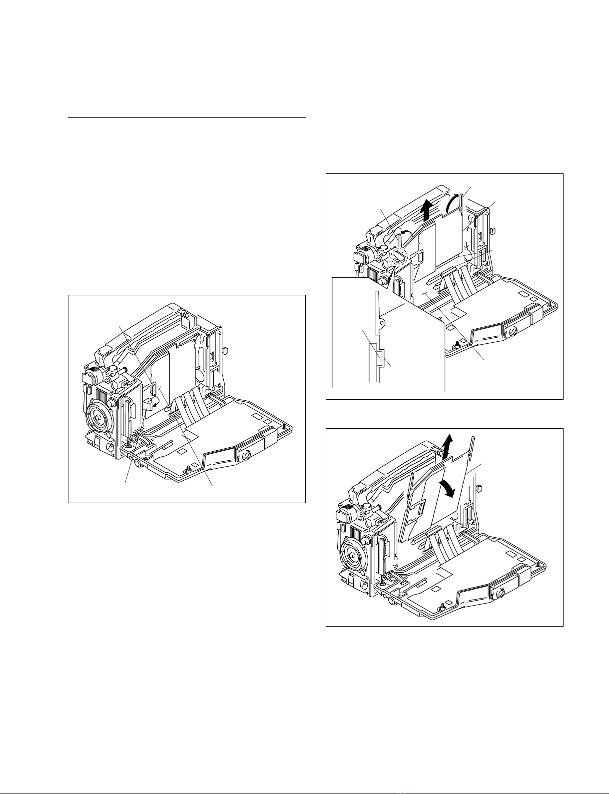
3. Removing the DVP Board Assembly 1-5. Removing and Installing the DVP Board Assembly
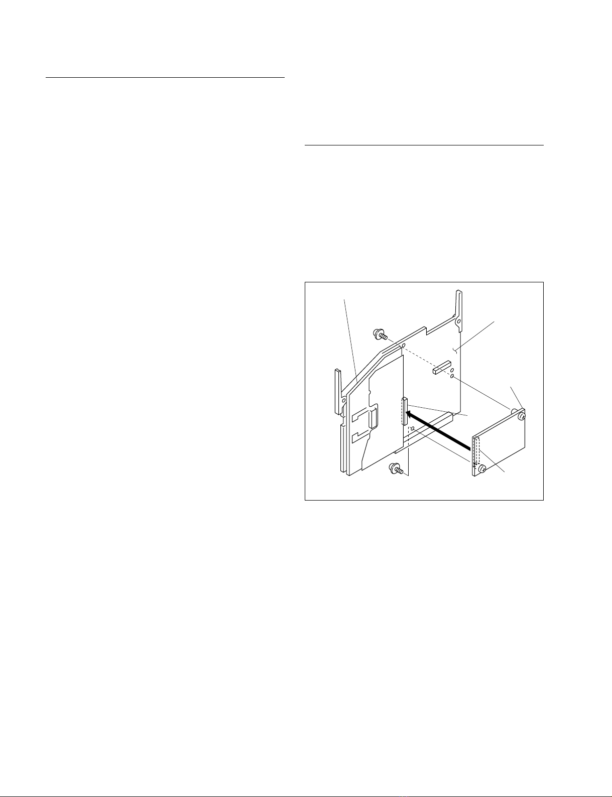
4. Installing the CBK-MB01 (MY-113 Board) 1-6. Installing the CBK-MB01 (MY-113 Board)
5. Installing the DVP Board Assembly 1-5. Removing and Installing the DVP Board Assembly
6. Installing the DCP Board Assembly 1-4. Removing and Installing the DCP Board Assembly
7. Closing the Inside Panel 1-3. Opening and Closing the Inside Panel Assembly
8. Operation Check 3-2-5. Starting a Shoot with a Few Seconds of Pre-Stored
Check that the cache rec function works correctly Picture Data (Picture Cache Function: with CBK-MB01)
(Refer to the DVW-970/970P Operation Manual)


 User manual")