Sony XCD-MV6 User manual

Technical Manual
A-DVH-100-11 (1)
Digital Video
Camera Module
© 2010 Sony Corporation
XCD-MV6

2
Table of Contents
Overview
Main Features ........................................................ 3
System Components .............................................. 4
Connection Diagram ............................................. 5
Location and Function of Parts and Operation .. 6
Front/Top/Bottom ............................................... 6
Rear .................................................................... 6
Installation ............................................................. 7
Fitting the lens .................................................... 7
Connecting the camera cable ............................ 7
When power supply from the IEEE1394b
connector is insufficient ................................... 7
Notes on Operation ................................................ 8
Phenomena Specific to CMOS Sensors ............... 8
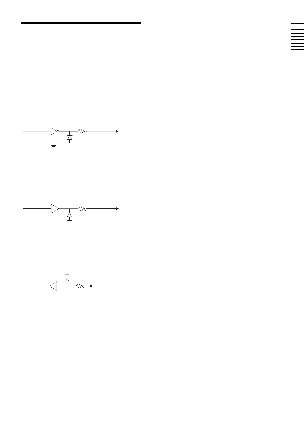
Strobe/GPIO Circuit ............................................. 9
Functions
Shutter .................................................................. 10
Trigger .................................................................. 10
Trigger Polarity ................................................... 10
Trigger Delay ....................................................... 10
Trigger Mode ....................................................... 11
Strobe Control ..................................................... 11
GPIO ..................................................................... 11
Memory Channel ................................................. 11
User Free Memory ............................................... 11
Broadcast Command ........................................... 12
1394 Bus Synchronization .................................. 12
Gain ...................................................................... 12
Brightness ............................................................. 12
Gamma ................................................................. 12
Pan ........................................................................ 13
Image Buffer (Memory Shot) ............................. 13
Partial Scan .......................................................... 14
Pseudo-Binning Mode ......................................... 15
16-bit Mode .......................................................... 15
Image Correction ................................................. 15
Flipping images horizontally and vertically ...... 15
Control
Camera Command Status Register ................... 16
ConfigurationROM ............................................. 17
Control Base Address .......................................... 19
Inquiring about Supported Video Modes ......... 19
Video Mode Settings (S800/S1600) .................... 19
Starting/Stopping Video Transfer
(ContinuousShot) ................................................. 19
OneShot, MultiShot and ImageBuffer .............. 20
Control of IIDC Standard Features ...................21
The formula for absolute value shutter control
register address ...............................................22
Control of IIDC Optional Features ....................23
Control of Sony’s Unique Features ....................24
Displaying the Test Chart .................................24
User Free Memory ............................................24
Vertical Stripe Correction .................................24
Blemish Correction ...........................................24
Shading correction ............................................25
Flipping Images Horizontally and Vertically ....26
Bus Synchronization .........................................26
Memory Shot ....................................................26
Notes on the Camera Operations .......................27
If Frame Rate Decrease Occurs ........................27
When Using Trigger Mode ...............................27
Increase in White Flecks and Noise .................27
Pseudo-binning mode sensitivity ......................28
Shutter Speed and Image Quality Assurance ...28
Performance Assured Visual Output ................28
Power Consumption ..........................................28
Specifications
Specifications ........................................................29
Video Modes Supported ......................................30
Appendix
Spectral Sensitivity (Relative Response)
Parameters ............................................................32
Dimensions ............................................................33

Overview
3
Overview
The XCD-MV6 digital video camera module employs
the IEEE1394b-2002 standard and is equipped with
quality digital camera features. Despite its compact size,
this camera is equipped with a host of features such as
digital signal processing in the camera which reduces
the load of image processing in a PC, bus
synchronization, and broadcast delivery of commands.
This digital output camera conforms to the IIDC 1.32
protocol, taking full advantage of IEEE1394
capabilities.
Main Features
High-speed transmission at 1.6 Gbps
Transmission speed supports the following two types:
S1600 (1.6 Gbps (1600Mbps)) and S800 (800 Mbps).
Equipped with a CMOS sensor
With a 1/3" CMOS Sensor, the camera can output video
at a frame rate of 60 fps with a image size of WVGA
(H:752 × V:480) and VGA (H:640 × V:480).
Digital signal processing
The camera is equipped with Sony's own correction
function which corrects pixel blemishes and vertical
stripes characteristic of CMOS Sensors.
In addition, it is also equipped with a function to correct
shading produced by lenses and light sources, achieving
high image quality required for machine vision use.
Broadcast delivery of commands
The camera settings for all the cameras connected to the
same bus can be changed at the same time. For example,
the gain or shutter speed is set to the same value on all
the cameras, or exposure starts on all the cameras
simultaneously using a software trigger.
Memory Channel
The memory channel allows storage of up to 15 sets of
camera settings such as gain and shutter.
Image Buffer (Memory Shot)
The image exposed from the sensor is stored in the
camera’s built-in memory. The stored image can be read
out using a command from the host PC when required.
The number of frames is not dependent on bit length.
The maximum number of frames is 100, regardless of
image size.
Partial scan
Partial scan clips a required angle of view (area) from
the entire screen to be read out. As a part of the image is
read out, the unit takes advantage of reduced image data
and high-speed transfer. The minimum clipping unit is
64 pixels × 24 lines.
Connector with fixing screws
The camera employs a fixing screw connector resistant
to vibration and shock in both the IEEE1394b and 8-pin
connectors.
Low power consumption, vibration and
shock-resistant structure, and compact
size
IIDC Ver.1.32 protocol compliant
XCD-MV6
Standard image size (H × V) 640 × 480 (VGA)
Bit length Mono8 100 frames maximum
Mono16 100 frames maximum

Overview
4
System Components
The camera module imaging system comprises the following products.
Products 1to 4are used for the basic configuration, and 1to 6for the optional configuration. (All the products
except the camera module are available separately.)
1Camera module
This is a small-size, high-resolution, camera
module using a CMOS sensor.
2IEEE1394b camera cable (commercially
available)
Connect this cable to the IEEE1394b connector on
the rear panel of the camera module. The power and
image/control signals are transmitted through this
cable. To prevent a poor connection or damage to
the camera or cable, use the cable equipped with
fixing screws.
3C-mount lens (commercially available)
Use an appropriate lens for the camera module and
usage.
4Camera module interface board (commercially
available)
This is inserted in slots such as the PCI Express bus
or PCI bus of the host equipment (PC etc.)
Select an IEEE1394b interface board to match your
system.
5DC-700/700CE camera adaptor (Sony)
Connect this adaptor to the camera module to
enable power supply from an ordinary AC power
source.
6Camera cable (commercially available)
Connect this cable to the 8-pin I/O connector on the
rear panel of the camera module. The cable is used
for power supply and exchange of trigger signals.
For details about the suitable cable, please contact
your Sony Dealer.
123
456

Overview
5
Connection Diagram
Note
To enable S1600 (1.6 Gbps (1600 Mbps) high-speed
transmission, you will require a S1600-compatible host
adapter card and IEEE1394b cable. For details, contact
your Sony dealer.
In addition, this equipment is exclusively for beta mode
use, so it is not possible to connect it to the IEEE1394a
host adapter card with the IEEE1394-9P/6P cable.
C-mount lens
Host equipment (PC, etc.)
IEEE1394b cable
Host adaptor card
XCD-MV6

Overview
6
Location and Function
of Parts and Operation
Front/Top/Bottom
1Lens mount (C-mount)
Attach any C-mount lens or other optical
equipment.
Note
The lens must not project more than 10 mm (13/32 inch)
from the lens mount.
1Lens mount face 210 mm (13/32 inch) or less
2Auxiliary holes (top)
3Reference holes (bottom)
These precision screw holes are for locking the
camera module. Locking the camera module into
these holes secures the optical axis alignment.
For details, see “Dimensions” on page 33.
Rear
4IEEE1394b connectors
Connect an IEEE1394b camera cable (not
supplied) to this connector.
58-pin I/O connector
When power from the IEEE1394b connector is
insufficient, power is supplied through this
connector.
1
2
3
3
Pin No. Signal Pin No. Signal
1TPB– 6VG
2TPB+ 7NC
3TPA– 8VP
4TPA+ 9TPBG
5TPAG
Pin No. Signal Pin No. Signal
1 Trigger IN 5 GPI1 IN
2 Strobe OUT 6 Power GND
3 GPO1 OUT 7 Power IN
4 GPI2 IN 8 GPO2 OUT

Overview
7
Installation
Fitting the lens
1
Remove the lens mount cap.
2
Screw in the lens (not supplied), and turn it until it
is secured.
Note
Clean the optical filter with a commercially available
blower brush to remove dust.
Connecting the camera cable
Connect a commercially available IEEE1394b camera
cable to the IEEE1394b connector and the 1394b
interface connector of your PC. When you connect the
cable, insert the cable connector into the IEEE1394b
connector until it snaps into place, holding it. Then,
tighten the fixing screws placed on both sides of the
cable connector.
1IEEE1394b connector
2Fixing screws
3IEEE1394b camera cable (not supplied)
Note
Loose fixing screws may cause a poor connection or
damage to the camera or cable. Be sure to tighten the
fixing screws.
When power supply from the
IEEE1394b connector is
insufficient
Power can be supplied to the camera module via the DC-
700/700CE camera adaptor (optional) and a camera
cable (optional) if power supply from the IEEE1394b
connector is insufficient.
18-pin I/O connector
2Camera cable
3to AC power source
4CAMERA connector
5-AC IN connector
6Trigger generator

Overview
8
Notes on Operation
Power supply
Power is supplied to the camera module via the
IEEE1394b cable connected to a PC. If the power supply
is insufficient, use the DC-700/700CE that supplies
stable power with less ripple or noise.
Foreign bodies
Be careful not to spill liquids, or drop any flammable or
metal objects in the camera body.
Locations for operation and storage
Avoid operation or storage in the following places.
• Extremely hot or cold locations. Recommended
temperature range is 0°C to 40°C (32°F to 104°F)
• Locations subject to strong vibration or shock
• Near generators of strong electromagnetic radiation
such as TV or radio transmitters
Care
Use a blower to remove dust from the surface of the lens
or optical filter. Clean the exterior with a soft, dry cloth.
If the camera is very grimy, apply a cloth soaked in a
mild detergent then wipe with a dry cloth. Do not apply
organic solvents such as alcohol which may damage the
finish.
Phenomena Specific to
CMOS Sensors
The following phenomena that may appear in images are
specific to CMOS sensors. They do not indicate
malfunctions.
White flecks
Although the CMOS sensors are produced with high-
precision technologies, fine white flecks may be
generated on the screen in rare cases, caused by cosmic
rays, etc.
This is related to the principle of CMOS sensors and is
not a malfunction.
The white flecks especially tend to be seen in the
following cases:
• when operating at a high environmental temperature
• when you have raised the gain (sensitivity)
• when using a slow shutter or the trigger cycle is long
Aliasing
When fine patterns, stripes, or lines are shot, they may
appear jagged or flicker.
Note on laser beams
Laser beams may damage a CMOS sensor. You are
cautioned that the surface of a CMOS sensor
should not be exposed to laser beam radiation in an
environment where a laser beam device is used.

Overview
9
Strobe/GPIO Circuit
Strobe Output / GPIO Circuit
The Strobe output and GPIO circuit is configured as
follows. Be sure to take note of this before use.
Strobe output circuit
This is a strobe output circuit diagram.
This is a standard CMOS level output (5 V).
The camera is equipped with a protective resistor of
220 Ω. Be sure to confirm the output waveform before
use.
GPO1/2 output circuit
This is a GPO1/2 output circuit diagram.
This is a standard CMOS level output (5 V).
Equipped with a protective resistor of 2.2 kΩ. Be sure to
confirm the output waveform before use.
GPI1/2 input circuit
This is a GPI1/2 input circuit diagram.
Compatible with standard TTL level input.
Equipped with a protective resistor of 10 kΩ. Be sure to
confirm the input waveform before use.
Strobe output
terminal
220 Ω
GPO1/2
output circuit
2.2 kΩ
GPI1/2 input
circuit
10 kΩ
10 pF

Functions
10
Functions
Shutter
This camera allows users to set manual shutter speeds.
The variable range extends from 20 microseconds to 1
seconds; relative values are indicated by a 12-bit integer,
and absolute values are indicated using a 32-bit floating
point value.
When setting an exposure time longer than the cycle of
the set frame rate, it sets to long exposure time mode and
the actual frame rate is reduced in accordance with the
exposure time.
The relationship between the parameter and the
exposure time is given by the following formulas,
where:
P = Parameter (004h to 3E8h)
E = Exposure time (s)
If P= 4
E = 0.00002
If 5 <= P <= 1000
Setting examples
4 (003h) : 20 µs (1/50000)
32 (020h) : 1 ms (1/1000)
100 (064h) : 10 ms (1/100)
1000 (3E8h) : 1 s
128 (080h) : 16.384 ms (1/60: default setting)
Note
This camera outputs images for 4 frames from the frame
changed by the shutter. Images effective from the fifth
frame are output. Be sure to take note of this before use.
Trigger
Trigger shutter is useful for capturing images in
response to a trigger signal that starts the exposure to
match a preset timing. It can also be used to capture an
image using multiple cameras with the same timing.
This camera supports a hardware trigger input from
8-pin connectors, and 2 types of software trigger set by
1394 bus command.
Note
Switching trigger signals may cause image disturbance.
Be sure to take note of this before use.
Trigger Polarity
This feature selects the active polarity of the hardware
trigger. There are positive and negative polarities so,
first, fix the trigger polarity and then use the other trigger
function.
Active polarity: Negative polarity (default setting)
Trigger Delay
This feature adds an internal delay to the trigger. It is
used to align the timing by adjusting the delay when the
trigger timing and object position are out of alignment,
or when fine-tuning the trigger signal timing in multiple
machines.
Note
Use the trigger delay when the input trigger cycle is long
enough for the trigger delay. The image will not be
output properly if the trigger delay value is longer than
the input trigger cycle.
E
1 s
20 µs
4 1000
P
Trigger
(positive polarity)
Exposure
Post delay trigger

Functions
11
Trigger Mode
This camera support 2 trigger modes: 0 and 1.
Trigger mode 0
Trigger mode 0 starts exposure by detecting the edge of
a trigger signal. The exposure time is determined by the
shutter parameter.
Trigger mode 1
Trigger mode 1 controls the exposure time by the width
of the trigger signal pulse. Input a trigger with a trigger
width (Tw) expressed as exposure time = Tw+4.45 µs.
Hardware trigger latency (Tl) from inputting the
hardware trigger from an 8-pin connector to the actual
exposure starting becomes fixed at 7.52 µs, as shown in
the below diagram which expands the exposure time
start part.
Trigger signal input conditions
Input a signal that satisfies the below levels.
Note
Trigger operations such as changing the shutter for each
trigger are not possible with this camera’s trigger mode.
A normal image is output for the first time by trigger
operations with a shutter setting equal to 5 frames or
more. Images for 4 frames cannot be output by the
camera itself. Be sure to take note of this before use.
In addition, with trigger mode 1, images are not output
normally when the jitter component of the trigger signal
itself is large. Keep the jitter component of the trigger
signal itself within 296 ns. Use trigger mode 0 if this
condition cannot be met.
Strobe Control
A strobe control output signal is assigned to the 8-pin
connector. This feature allows strobe equipment
connected to the camera to directly emit light. Output
delay and width can be set for the exposure time.
Camera exposure time can be output without change.
GPIO
A general-purpose I/O port with a 2-bit output and 2-bit
input is assigned in the 8-pin connector.
This port is used for reading information of external
switches and sensors from the camera and controlling
external devices.
Memory Channel
Since this camera is equipped with 15 memory channels
to hold camera settings, it can presave parameter settings
to match scenes.
The applicable parameters include: brightness, gamma,
shutter, gain, pan, trigger mode, trigger delay, strobe
ON/OFF, strobe delay, width, and GPO.
User Free Memory
This camera is equipped with a 256-byte memory space
so the user can write and read data freely.
The written data is retained after the power is turned off.
For example, the user can name the camera and note the
installation conditions using this memory space.
The memory content is retained even if the camera
initialization is performed.
Trigger mode 0 (negative polarity)
Exposure
Trigger
Trigger mode 1 (negative polarity)
Exposure
Trigger
Tw+4.45 µs
Trigger mode 0 (negative polarity)
Exposure
Trigger
T1=7.52 µs
When set to negative
(default setting)
Low-level
DC 0 to 0.5 V
High-level
DC 5 to 24 V
DC 0 V DC 0 V
When set to positive
DC 0 V
Trigger
(positive polarity)
Exposure
Strobe output signal
Delay
Low-level
DC 0 to 0.5 V
High-level
DC 4 to 5 V

Functions
12
Broadcast Command
The normal 1394 communication method specifies the
node number at the host side so that only a specified
camera responds to the command.
If the node number is set to 63, all the cameras
connected to the same bus can receive the command
simultaneously, i.e., only one command issued from the
host can control multiple cameras at the same time.
Example: To broadcast a software trigger
1. Connect multiple cameras to the same bus.
2. Set the video mode and frame rate appropriately on
each camera and prepare the cameras for sending
images at the same time.
3. Set each camera to the software trigger mode.
4. Issue a software command for node number 63.
Now all the cameras start exposure and output images
simultaneously.
All the commands including the video mode setting and
the feature control are capable of broadcasting except
the block writing command.
When setting different types of cameras using a
broadcast command, be careful not to issue a command
that the cameras do not support.
1394 Bus Synchronization
This camera is equipped with a function that
synchronizes with the cycle time resistor of the 1394 bus
to define exposure timing. This synchronization occurs
at the start of exposure.
When the bus synchronization function is enabled,
multiple cameras connected to the same bus will
automatically synchronize with the 1394 bus and
operate. As band restrictions will be applied depending
on the transmission rate configured, you must configure
a video mode that will allow simultaneous video
transmission.
When long exposure mode (i.e., when the exposure time
configured is longer than the image transmission
frequency), pseudo-binning mode, or partial scan mode
is configured, the synchronization function will be
disabled.
The 1394 bus synchronization function includes jitter
between the bus clock and camera clock. To obtain more
accurate synchronization, perform external
synchronization via hardware triggering.
Gain
This camera allows manual gain settings of up to 1 to 8
times in 0.125 increments. The analog gain is 1 to 4
times, while the digital gain is 4.125 to 8 times.
Note
The timing reflected by the gain is from the 2nd frame.
Be sure to take note of this before use.
Brightness
This feature controls the black level of a video image.
Gamma
This feature sets the gamma coefficient. Gamma
coefficient values can be set at the following settings
between a variable range of 0 to 15.
0: Linear
1 to 15: 0.1 to 1.5 curve coefficient (increments of 0.1)
Gamma offset allows you to set the black standard value
at a variable range between 0 to 255 (1/4 the low-level
side of the 0 to 1023 output range during 10-bit output).
Levels equal to or below the black standard value set
with gamma offset can prevent too much white in the
black level because the gamma level is fixed at 1.
Output
1023
γ= 0.1 to 1.5
0 1023
Input
Offset
0 to 255
Output = Input

Functions
13
Pan
Pan is a function used to move a camera left and right.
However this camera supports a video mode much
smaller than the image sensor’s effective pixels by
cutting out images from the whole screen. You can
specify the portion to be cut out using Pan commands.
The variable range differs according to the selected
video mode.
When a video mode is changed, the pan values are set to
the default setting.
Image Buffer (Memory
Shot)
The camera has image buffer (Memory Shot) that
temporarily stores an image in the frame memory inside
the camera and transfers it later.
When multiple cameras are connected in the same bus,
all the cameras may not output images at the same time
due to the restriction of the set transmission rate.
ImageBuffer (Memory Shot) may resolve this
inconvenience.
When exposure starts, each camera stores an image in
the frame memory without allocating the isochronous
resource.
When outputting, each PC outputs the image from the
camera allocating the isochronous resource.
The number of images to be stored is 100 at maximum.

Functions
14
Partial Scan
The partial scan is a function for outputting part of a whole image as a region of interest on the whole image. Based on
the unit cell as the unit, continuous parts can be selected. Only rectangles can be selected. The screen cannot be cut in
convex and L shapes.
The minimum unit size for partial scan is 64 pixels × 24 lines. The cut-out position can be set in unit of 4 pixels × 4 lines.
For high-speed scanning, set the maximum packet size.
When using multiple cameras at the same time, set a small packet size that falls within the set transmission rate band.
When using Partial scan mode, set Format7, Mode0.
Note
By selecting Partial scan mode, it is possible to set the maximum value of 752 pixels for the horizontal size of the image.
However, because the horizontal direction increases by a factor of 64, the image data is set to 768 pixels causing 16
pixel-wide completely black data to be output in the right edge of the image.
Although this completely black data will definitely appear in the right edge of the image when the horizontal size is set
to 752 pixels, this is not a malfunction because it is caused by a difference between the sensor's effective resolution and
the values set for the image size.
Vertical (Vertical Direction)
Horizontal (Horizontal Direction)
Cutting by Partial scan mode

Functions
15
Pseudo-Binning Mode
This feature compresses images in units of 2 pixels and
multiplies the frame rate speed in the vertical direction
only.
There are two types of binning: 1 × 2 binning when the
output image is compressed in the vertical direction
only, and 2 × 2 binning when the image is compressed in
both the vertical and horizontal directions.
When Binning mode is used, set either Format7 Mode1
(2 × 2 binning), or Format7 Mode2 (1 × 2 binning).
Note
If 1 × 2 binning mode is used when the image level
difference of the 2 value is above 50 steps for 8-bit
mode, a line including darker pixels will be selected and
output. If it is 50 STEP or below, the average value of the
2 pixels will be output.
The fixed and average value of the 2 pixels is output for
horizontal direction binning in 2 × 2 binning mode. The
frame rate does not increase for horizontal direction
binning.
In addition, the image correction function does not work
in pseudo-binning mode.
16-bit Mode
This camera supports 16-bit Black & white
(Monochrome) mode. Only the least significant 10 bits
of the 16 bits will handle data. The upper 6 bits will be
filled with zeros.
Image Correction
This camera is equipped with the following image
correction functions.
Vertical stripe correction (default setting: ON)
This feature corrects vertical stripes generated from the
image sensor. Only ON/OFF can be selected for this
feature.
Blemish correction (default setting: ON)
This feature corrects bugs in the image sensor. Default
and user settings can be selected.
Shading correction (default setting: OFF)
This features corrects shading caused by light falloff at
lens edges, uneven brightness, and sensors. This can
only be selected with user settings, and either the
average value or the pixel-level maximum value within
1 frame can be selected as the target value. It would be
useful to make the following distinction when
generating shading correction values: little noise -
maximum value; lots of noise - average value.
When calibrating blemish and shading correction user
settings, be sure to capture subjects that fulfill the
following conditions.
Blemish correction: Completely black images
Shading correction: full-frame medium visual level
(50% grey level) images for which you have used a
uniform subject such as white paper in your lighting
environment
Be sure to decide the shutter, gain and temperature
environment in advance when calibrating settings. Refer
to the explanation in the control register for more details
about setup steps.
Notes
• The dynamic range of the visual level may reduce
slightly when correcting vertical stripes. Be sure to
take note of this before use.
• The resolution may reduce when correcting
blemishes. Be sure to take note of this before use.
• When correcting the shading correction average value,
the dynamic range of the visual level may drop by a
large degree depending on the original shading
amount. Be sure to take note of this before use. In
addition, the maximum shading correction value may
be falsely recognized in environments where there is a
lot of noise. Be sure to take note of this before use.
Flipping images
horizontally and
vertically
This camera can flip images horizontally and vertically.
This is useful in situations when the camera itself cannot
be flipped horizontally and vertically.
000000dd dddddddd

Control
16
Control
Camera Command Status Register
This camera complies with IIDC 1394-based Digital Camera Specification, Version 1.32 (hereinafter referred to as IIDC
v1.32).
The standards document can be purchased from 1394TA (the 1394 Trade Association). As it is very helpful in
understanding the explanations in this Technical Manual, we recommend that you purchase a copy of IIDC v1.32.
Memory Map
1394 devices have a 64-bit address space. The upper 10
bits show the bus ID (0-1023), and the next six bits show
the node ID (0-63). The IIDC standards require the next
20 bits to be 1.
The remaining 28 bits can be allocated to the camera as
addresses.
The bus and node IDs may be changed if the topology is
restructured because of bus reset, so only the least
significant 32 address bits are shown in this Guide.
bbbbbbbb bbnnnnnn 11111111 11111111 11110000 11110000 00000000 00000000
NodeID
BusID Must be 1 Address used by the camera
Address Resister
F0000000 Base address
F0000400 ConfigROM area
F0F00000 Base address for camera
commands
F0F00000 CameraInitialize
F0F00100 Video Format Inq
F0F00180 Video Mode Inq
F0F00200 Frame Rate Inq
F0F002E0 Format7 CSR Inq
F0F00400 Basic Func Inq
F0F00500 Feature Element Inq
F0F00600 Isochronous Control register
F0F0071C AbsoluteControlCSR Inq for
Shutter
F0F00800 FeatureControl
F0F00970 AbsoluteControlCSR for Shutter
F0F10000 Format7Mode0 CSR
F0F11000 Format7Mode1 CSR
F0F12000 Format7Mode2 CSR
F0F30000 AccessControlRegister
F0F40000 MemoryShotControl
F0F50000 UserFreeMemory

Control
17
ConfigurationROM
The ConfigurationROM is normally used for the OS to identify the device.
The serial number and firmware version of the camera are stored in ConfigurationROM to be used when required. Note
that the setting method for the serial number and firmware version information is of Sony’s unique specification and is
not compatible with cameras of other manufacturers.
With the exception of bits 8 to 15 of the 400h offset address field, the length of the entire ConfigROM is made up of
21h Quadlets. Therefore, the ConfigROM from 400h to 487h is 136 bytes.
The UnitDirectory offset address is required to be
420h + 000001h × 4 = 424h
For offset address 424h, the length of the UnitDirectory is 3 Quadlets.
UnitSpecID (00A02Dh) conforms to 1394TA standards.
UnitSoftwareVersion (000102h) conforms to IIDC Standards, Version 1.3.
The offset address of UnitDependentInfo is required to be
430h + 000001h × 4 = 434h
Offset 0-7 8-15 16-23 24-31
Bus Info Block 400h 04 21 ROM CRC
404h 31 33 39 34
408h 20 FF 92 14
40ch 08 00 46 10 NodeVendorID/ChipID-Hi
410h 00 37 1A 96 Chip ID-Lo
Root
Directory
414h 0003 CRC
418h 03 08 00 46 ModuleVendorID
41ch 0C 00 83 C0
420h D1 00 00 01 UnitDirectoryOffset
Offset 0-7 8-15 16-23 24-31
Unit Directory 424h 0003 CRC
428h 12 00 A0 2D UnitSpecID
42Ch13000102UnitSoftwareVersion
430h D4 00 00 01 UnitDependentDirectory Offset
Offset 0-7 8-15 16-23 24-31
Unit
Dependent
Info
434h 000B CRC
438h 40 3C 00 00 CommandRegsBase
43ch 81 00 00 0A VendorNameLeaf
440h 82 00 00 0D ModelNameLeaf
444h 38 00 00 20 Unit_sub_sw_version
448h 39 00 00 00 Reserved
44Ch 3A 00 00 00 Reserved
450h 3B 00 00 00 Reserved
454h 3C 00 01 00 Vendor_unique_info_0
458h 3D 01 00 00 Vendor_unique_info_1
45Ch 3E 00 00 30 Vendor_unique_info_2
460h 3F 01 86 A1 Vendor_unique_info_3

Control
18
For offset address 434h, the length of the UnitDependentInfo is 0Bh Quadlets.
CommandRegsBase is the base address of the camera control register.
F0000000h + 3c0000h × 4 = F0F00000h
The offset address of VendorNameLeaf is required to be
43Ch + 00000Ah × 4 = 464h
The offset address of ModelNameLeaf is required to be
440h + 00000Dh × 4 = 474h
Unit_sub_sw_version conforms to IIDC Standards, Version 1.32.
Vendor_unique_info 0 to Vendor_unique_info 3 are terms of information that the vendor of the camera can define.
The meanings in this camera are as follows:
Vendor_unique_info_0 is the firmware version.
Vendor_unique_info_1 is the hardware version.
Vendor_unique_info_2 is the link version.
Vendor_unique_info_3 is the serial number of the camera.
VendorNameLeaf
For offset address 464h, the length of the VendorNameLeaf is 3 Quadlets.
The subsequent 8 bytes are fixed at 00.
After that, the four characters for “SONY” are entered.
ModelNameLeaf
For offset address 474h, the length of the ModelNameLeaf is 4 Quadlets.
The subsequent 8 bytes are fixed at 00.
After that, the model name is entered.
Offset 0-7 8-15 16-23 24-31
Vender Name Leaf 464h 0003 CRC
468h 00 00 00 00
46h00000000
470ch 53 4F 4E 59 “ SONY ”
Offset 0-7 8-15 16-23 24-31
Model Name Leaf 474h 0004 CRC
478h 00 00 00 00
47ch00000000
480h5843442D
“ XCD- ”
484h 4D 56 36 00 “ MV6 ”

Control
19
Control Base Address
Every register address is decided based on the base
address found in the CommandRegsBase field of
ConfigrationROM. F0F00000h is the control base
address on this camera.
Inquiring about
Supported Video Modes
First, we will find out what video formats are supported.
Next, for each format, we will find out which video
modes are supported.
Format0
Format7
Next, for each video mode, we will find out which frame
rates are supported.
Video Mode Settings
(S800/S1600)
Select the video mode you want to use from the tables,
and make the required settings.
As examples, the register settings for Format0, Mode5,
and a frame rate of 60 fps are shown.
In addition, an isochronous transfer speed of 800 Mbps,
and isochronous channel 0 are used in these examples.
Normally, set the isochronous transfer speed to
800 Mbps or 1600 Mbps.
When multiple cameras are used simultaneously, set
different isochronous channels for each.
Starting/Stopping Video
Transfer
(ContinuousShot)
In the device driver, after the preparations for receiving
isochronous data are made, video transfer starts when
the following commands are issued.
When the following command is issued video transfer
stops.
Data
Address XCD-MV6
F0F00100h 81000000h
Data
Address XCD-MV6
F0F00180h 06000000h
Data
Address XCD-MV6
F0F0019Ch E0000000h
Data
Address XCD-MV6
F0F00214h
(Format0Mode5)
FC000000h
F0F00218h
(Format0Mode6)
FC000000h
Data
Address XCD-MV6
F0F00600h
(FrameRate)
A0000000h
F0F00604h
(VideoMode)
A0000000h
F0F00608h
(VideoFormat)
00000000h
F0F0060Ch
(IsoChannel / IsoSpeed)
00008003h
Address Data
F0F00614h 80000000h
Address Data
F0F00614h 00000000h

Control
20
OneShot, MultiShot and
ImageBuffer
This camera supports both OneShot, MultiShot and
ImageBuffer commands. With a OneShot command,
after outputting just one single-frame live image is
output. With a MultiShot command, the specified
number of images are output. ImageBuffer outputs a
specified number of images stored in the camera.
Issue the following commands when using OneShot and
MultiShot.
ImageBufferCtr OFF / TransferDataSelect
LiveData
OneShot
MultiShot
nnnn indicates the number of frames to be output. You
can specify any number between 0001h and FFFFh (1
and 65535). If 0000h is specified, you can think of it as
being 1.
Issue the following commands to start saving
ImageBuffer images.
ImageBufferCtr ON
Issue the following commands to stop saving
ImageBuffer images.
ImageBufferCtr OFF
When the following command is read, the maximum
number of saved frames and the number of currently
saved frames is understood.
MaxNumImages / NumberOfImages
64h (100) is the maximum number of saved frames. nn
is the number of currently saved frames. It will be 00h to
64h (0 to 100).
Issue the following commands to output ImageBuffer
images.
TransferDataSelect BufferedImageData
ImageBufferRead
nn specifies the number of output frames. It is possible
to specify between 01h to 64h (1 to 100). When 00h is
specified it is construed that 1 was set.
Execution of ContinuousShot, OneShot, MultiShot and
ImageBuffer are prioritized as follows. When a
command with higher priority is being executed, the one
with the lower priority is ignored.
ContinuousShot > OneShot > MultiShot/ImageBuffer
Address Data
F0F00634h 00000000h
Address Data
F0F0061Ch 80000000h
Address Data
F0F0061Ch 4000nnnnh
Address Data
F0F00634h 80000000h
Address Data
F0F00634h 00000000h
Address Data
F0F00634h x0640nnh
Address Data
F0F00634h 40000000h
Address Data
F0F0061Ch 400000nnh
Other manuals for XCD-MV6
1
Table of contents
Other Sony Camera Accessories manuals

Sony
Sony LCS-EMB1A User manual

Sony
Sony VF-R25NK User manual

Sony
Sony BKP-7090 User manual

Sony
Sony FDA-ME1AM User manual

Sony
Sony US14430GR Instruction Manual

Sony
Sony LC-H300 User manual

Sony
Sony HDVF-C35W User manual

Sony
Sony CA-D50 User manual

Sony
Sony APK-WB Operating Instructions - Precautions User manual

Sony
Sony AJK-THA User manual

Sony
Sony ACC-CTBN User manual

Sony
Sony VCT-D480RM User manual

Sony
Sony XCD-V50 User manual

Sony
Sony FA-TC1AM User manual

Sony
Sony CCU-590 User manual

Sony
Sony GP-VPT2BT User manual

Sony
Sony SPK-HCB Operating instructions

Sony
Sony CA4000 User manual

Sony
Sony FCB-EV7520A User manual

Sony
Sony AKA-AF1 User manual