Wesa ST Series User manual

Wesa-Armaturen GmbH
Wesa
Operating manual
Spanninger Str. 5 Fax +49 (0)7181-404-33 Http www.wesa-armaturen.de
Pneumatic rotary drive
units
-73650 Winterbach
Type DT | ST
Date of issue
10
-
201
9
OPERATING MANUAL
Single-action [ST] | Double-action [DT]
PNEUMATIC ROTAR DRIVE UNITS
This operating manual contains important information relating to the installation,
function, maintenance and storage of AEROMATIC rotary drive units. Please read it
thoroughly and keep it safe for future reference. Only trained, qualified personnel
should maintain these rotary drive units.
Important Failure to eed t e following warnings could result in dangers and invalidate
t e seller's warranty. Please contact t e seller if you ave any queries.

OPERATING MANUAL
Pneumatic rotary drive units type ST | DT
Wesa
Page
1
Spanninger Str. 5 Fax +49 (0)7181-404-33 Http www.wesa-armaturen.de
Operating manual
-73650 Winterbach
Drive units ST | DT
Date of issue
10
-
201
9
WARRANT
Aeromatic provides a warranty for its pneumatic servo drive units for a period of 24 mont s from t e
date of delivery. T e warranty covers any defects in t e material supplied by us. T e above warranty
includes an obligation on t e part of Aeromatic GmbH to repair and replace parts w ic t e
manufacturer as acknowledged as defective and to refinis /replace t em on an ex-works basis.
T e warranty will be voided in t e following cases:
o If t e conditions of use do not comply wit t e intended use or t e tec nical specifications of t e
servo drive units.
o If t e servo drive units are not installed correctly.
o If t e servo drive units are not used for t eir intended purpose.
T e warranty does not include possible compensation in any circumstances. Apart from t e above
warranty, Aeromatic cannot provide any ot er services w ic are regarded as eit er expressly offered
or taken for granted. Furt ermore, Aeromatic cannot accept any liability for direct or indirect damages
of any kind.
Manual for installation, operation and maintenance
Pneumatic rotary drive units with rack and pinion gearing
1.0 Introduction
6.0
Installation of components
11.0
ISO connections
2.0 Storage
7.0
Double-action servo drive units
12.0
Torques
3.0 Function c aracteristics
8.0
Single-action servo drive units
4.0 Installation
9.0
Installation of spring sets
5.0 Component removal
10.0
Description – drawing
1.0. Introduction
Aeromatic sells a wide range of pneumatic servo drive units wit rack and pinion gearing. T ey are
designed for actuating industrial fittings for liquid media and gases suc as ballcocks or s ut-off valves.
T eir power is best supplied by oiled compressed air. T e minimum service life as been tested at 1
million switc cycles. T e initial greasing of t e servo drive units is sufficient for 500,000 switc cycles if
t e units are used for t eir intended purpose. T e pneumatic servo drive units are available in a double-
action version (wit out reset springs) wit a swing angle of 90° (120°, 130° and 180° to order) and as a
single-action version (reset by spring force) wit a swing angle of 90°.
2.0. Storage
All pneumatic servo drive units are supplied ready-greased. T e compressed air connections are
protected from t e ingress of water or ot er materials during storage and transport by sealing plugs.
T e servo drive units s ould be stored in an enclosed room to prevent armful environmental influences.
If t e servo drive units are stored for a lengt y period before installation, t ey must be actuated at
regular intervals to prevent t e permanent deformation of t e seals.

OPERATING MANUAL
Pneumatic rotary drive units type ST | DT
Wesa
Page
2
Spanninger Str. 5 Fax +49 (0)7181-404-33 Http www.wesa-armaturen.de
Operating manual
-73650 Winterbach
Drive units ST | DT
Date of issue
10
-
201
9
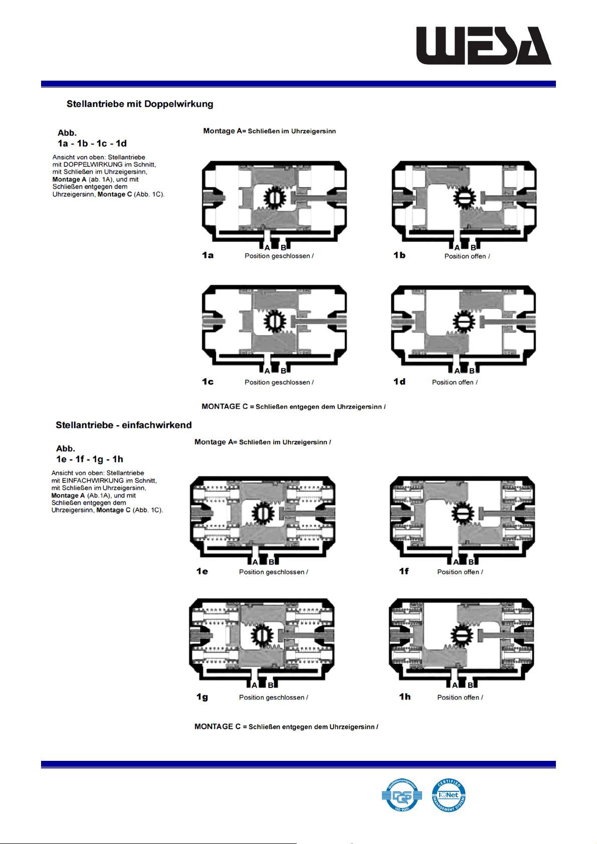
3.0. Function characteristics
T e pneumatic servo drive units ave t e function c aracteristics s own in Figures 1A-1B-1C-1D / 1E-1F-
1G-1H. Compressed air connection A (2) is connected wit t e ollow c amber between t e pistons and
compressed air connection B (4) is connected wit t e external ollow c ambers between t e pistons
and t e side covers. T e servo drive units are supplied as standard wit an octagon socket on t e output
side in w ic eit er an octagonal s aft or a square s aft can be fitted in any configuration (45° or 90°).
To order t e servo drive units can also be supplied wit t e output versions listed below.
T e compressed air connection can be made direct at t e compressed air connections or t roug control
valves wit a NAMUR connection.
Double-action servo drive units (wit out reset springs)
If compressed air is supplied to compressed air connection A (2), t e pistons move outwards as far as
possible up to t e stroke limiting pin and t e drive pinion moves in a 90° swing movement. W en
compressed air is supplied to connection B (4), t e outer c ambers of t e drive ousing are filled wit
compressed air and t e pistons returned to t eir initial positions. T e drive pinion returns to its original
position t roug a 90° swing movement.
Single-action servo drive units ( wit reset springs)
If compressed air is supplied to compressed air connection A (2), t e pistons move outwards as far as
possible up to t e stroke limiting pin w ic tensions t e reset springs. W en t e compressed air supply
at compressed air connection A (2) is switc ed off, t e pistons are pus ed back to t eir original positions
by t e tensioned springs. If t e servo drive units also ave a stroke limit for t e inner position of t e
pistons (initial position), t ey move back to t e initial position as far as possible up to t at limit.
4.0. Installation
Important safety information
During installation, t e drive unit must be depressurised for safety reasons. W en connecting t e air to
t e drive unit, ensure extreme cleanliness, wit t e t read connections, screw connections and seals, in
particular, being clean and dirt-free. If you install accessories on t e drive unit, ensure t at t e top end
of t e s aft remains clear so t at if it needs to be controlled manually at a later date, t is is possible.
Before you install t e drive unit on a fitting, ensure t at t e fitting is in t e correct initial position
depending on t e required direction of rotation.
T e servo drives are designed to ensure easy, straig tforward installation. T ey ave ISO 511 (DIN 333/9)
interfaces to connect fittings, signal units and control units. If t e appropriate fittings are used, t ey are
suitable for direct installation and also for installation on fittings wit a s aft adapter and installation
bridge.

OPERATING MANUAL
Pneumatic rotary drive units type ST | DT
Wesa
Page
3
Spanninger Str. 5 Fax +49 (0)7181-404-33 Http www.wesa-armaturen.de
Operating manual
-73650 Winterbach
Drive units ST | DT
Date of issue
10
-
201
9
4.1.
C eck t e fitting and servo drive are in t eir initial positions (default positions) before installation.
4.2.1.
Installation directly on fittings: Position t e servo drive on t e fitting, ensuring t at is correctly
seated and t at t e fitting s aft moves easily (see note).
4.2.2.
Installation on fittings wit an installation bridge: Fit installation pitc es on t e servo drive unit
for fastening it on fittings onto w ic it cannot be directly mounted. T en install t e s aft adapter
in t e output of t e servo drive unit. T en install t e fitting on t e bridge. Ensure t at it is seated
correctly and moves easily. Tig ten all t e fastening screws slig tly (see note).
Important note: After assembly, do not tig ten t e screws too muc so as to ensure t at t e
components are balanced and aligned by t e swing movement during t e first few switc cycles and t e
function test.
4.3.
Supply t e servo drive unit wit compressed air t roug compressed air connection A (2).
Important: Ensure t at t e rotary movement of t e drive unit does not go beyond t e maximum
rotary movement of t e fitting.
Important safety information Do not insert anyt ing into t e fitting and do not reac into t e fitting
during t e function test.
Actuate t e servo drive unit and t e fitting several times by supplying compressed air to t e compressed
air connections alternately. Pay close attention to ensuring t at t e components move easily and are
aligned. W en all t e components ave been correctly installed and t e fitting is actuated perfectly,
tig ten all t e screws used to fasten t e fitting to t e drive unit wit t e specified torque.
4.4.
After completing t e installation work, adjust t e stroke limiting pins for t e servo drive unit to
ensure t at t e fitting opens and closes correctly. Refer to section 6.0 ff. for details of t e
procedure.
5.0. Removing the servo drive units
5.1.
T e attac ed exploded drawing provides an illustration of t e components and t eir layout.
5.2.
Disconnect t e servo drive unit from all pneumatic and electrical connections.
Warning Never dismantle a servo drive unit w ic is still connected to t e compressed air supply. Danger
of injury
5.3.
Mec anically disconnect t e servo drive unit from t e fitting. If t ere is one, undo t e installation
support or adapter to t e fitting. Remove any accessory parts suc as solenoid valves, limit switc es
or position controllers and place t e servo drive unit on a clean work benc .
5.4.
On servo drive units wit adjustable stroke limits at bot sides,
undo t e four screws on eac side cover, remove t e left- and side cover t en undo t e locknut
and tig ten t e pin on t e internal stroke limit of t e rig t- and side cover to remove t e side
cover. On servo drive units wit an adjustable stroke limit at one side, remove t e four screws on
t e side cover and remove t e side cover from t e ousing.

OPERATING MANUAL
Pneumatic rotary drive units type ST | DT
Wesa
Page
4
Spanninger Str. 5 Fax +49 (0)7181-404-33 Http www.wesa-armaturen.de
Operating manual
-73650 Winterbach
Drive units ST | DT
Date of issue
10
-
201
9
5.5.
Remove t e O-rings from t e side covers (note: if t e servo drive unit is not relatively new, we
recommend t at you replace all t e O-rings on it, see Table 2A).
5.6.
Turn t e pinion anti-clockwise (note: if it is a C installation model, t e pinion must be turned in t e
opposite direction) until t e pistons ave come free from t e pinion so t at t ey can be removed
by and, see Fig. 4. If t e manual removal of t e pistons from t e ousing of t e servo drive unit
proves difficult, t e pistons can be pulled out using pliers (position t em on t e spring cups on t e
piston). Ensure t at t e surfaces of t e pistons are not damaged. W en removing t e pistons, note
t e original position to ensure t at t e pistons are positioned correctly during reassembly.
Warning: Never use compressed air to pus t e pistons out of t e servo drive unit ousing. Danger of
injury.
5.7.
Remove t e locking ring (Seeger ring) and t e was er on t e ring from t e pinion (top). Place t e
servo drive unit on two wooden supports so t at t e pinion can be pus ed easily from t e top out
of t e servo drive unit ousing. Use a rubber or plastic mallet if necessary to tap gently on t e upper
end of t e pinion. T en remove t e pinion from t e bottom w ole of t e drive ousing (Fig. 5).
Tables 2A and 2B s ow t e spare part series of t e slide elements and O-ring seals.
6.0. Installation of components
6.1.
Inspect all contact and wearing surfaces for wear or possible damage.
Note: Ensure t at all t e parts are still wit in t e tolerance specified by t e manufacturer.
6.2.
Ensure t at all t e metal parts are clean and free of burr and c ips.
6.3.
lubricate t e interior of t e cylinder c ambers, t e seats of t e O-rings and t e slide surfaces of t e
pinion and pistons wit MO-Bilux EP 2 or equivalent grease w ic is suitable for t e temperature
range between -20° C and +130° C.
Note: Special grease is required for operation in lower or ig er temperatures. Please contact us direct
for furt er details. If t e servo drive unit as already been used, we recommend t at you replace all t e
O-ring seals to ensure safe, perfect operation.
6.4.
Fit all t e slide jaws and guide rings on t e pistons and pinion, t en fit t e O-rings on t e pistons,
ousing cover and pinion.
6.5.
Insert t e pinion into t e servo drive unit ousing. Fit t e Delrin was er and t e locking ring (Seeger
ring) to t is upper part projecting out of t e ousing.
6.6
Insert t e pistons into t e cylinder ousing until t e racks are in contact wit t e pinion. Ensure
t at t e pistons are clearly aligned inside t e cylinder ousing, t ey do not jam and t e pistons are
symmetrically positioned wit t e drive pinion in t e connection.

OPERATING MANUAL
Pneumatic rotary drive units type ST | DT
Wesa
Page
5
Spanninger Str. 5 Fax +49 (0)7181-404-33 Http www.wesa-armaturen.de
Operating manual
-73650 Winterbach
Drive units ST | DT
Date of issue
10
-
201
9
6.7.
Exert t e same pressure on bot pistons until t ey are fully connected to t e pinion. T en turn
t e pinion itself until t e servo drive unit is completely closed.
6.8
C eck t e upper end of t e pinion to ensure it is correctly aligned. If t e guide-indicator c amfer
is perpendicular to t e cylinder body, please go to section 6.9. If t e pinion is not correctly
positioned, proceed as described in 6.8b.
6.8.b.
Turn t e servo drive unit to one side wit t e bore ole in t e body vertical. Turn t e pinion anti-
clockwise until t e two pistons are released from t e pinion. Closely servo drive unit again and
c eck t at t e pinion is in t e correct position. Repeat t is process until t e pinion reac es its
correct position.
6.9.
Insert t e springs on servo drive units wit a SINGLE-ACTION
(see section 7.04 instructions on inserting t e springs).
6.10.
Servo drive units wit limit point settings on bot sides.
Fit t e side covers ensuring t at t eir positions are correct (see Figures 6 and 8). T en insert t e
pin for t e internal stroke limit into t e central t read of t e rig t- and side cover and secure it
until t e tip of t e stroke limit pin touc es t e outer surface of t e piston. Use t e same procedure
on t e opposite stroke limit pin.
Note: Tig ten t e screws crossways to ensure t at t e O-rings are correctly positioned.
6.11
T e screws on t e eads must be tig tened alternately using t e torque specified by t e
manufacturer. See Table 3 for t e correct torques for t e screws.
Warning Never pressurise t e servo drive unit before t e pinion as been fastened wit t e Seeger ring
and t e eads ave been locked wit t e tig tened screws.
6.12.
Pressurise t e rig t connector on t e servo drive unit ousing and c eck for leaks. T ese leaks
may occur near t e connection between t e ousing and t e eads. If you find an air leak near a
ead, t e ead must be removed and t e O-ring c ecked to ensure it is in t e correct position. If
t e seal is OK, repeat t e procedure from point 6.11. Pressurise t e left connector of t e server
drive unit to c eck for possible air leaks from t e upper and lower area of t e pinion. If t ere is
an air leak from t e seats of t e pinion, proceed as described in section 5.6 to remove t e pinion
from t e servo drive unit ousing, ensuring t at t e pistons inside t e servo drive unit are not
moved. C eck t e condition of t e upper or lower O-ring or bot on t e pinion, depending on
w ere t e leak occurred. If t e O-rings are in perfect condition, ensured t at t ere is no burr or
c ips in t e seats of t e O-rings. Clean t en carefully and fit t e O-rings back into t eir grooves.
Install t e pinion again ensuring t at its perpendicular position relative to t e axis of t e servo
drive unit ousing is t e same as w en it was removed and also ensure t at it is inserted correctly
between t e teet of t e pistons w ic are still in position inside t e servo drive unit ousing.
Please contact us if t e problem continues to exist.

OPERATING MANUAL
Pneumatic rotary drive units type ST | DT
Wesa
Page
6
Spanninger Str. 5 Fax +49 (0)7181-404-33 Http www.wesa-armaturen.de
Operating manual
-73650 Winterbach
Drive units ST | DT
Date of issue
10
-
201
9

OPERATING MANUAL
Pneumatic rotary drive units type ST | DT
Wesa
Page
7
Spanninger Str. 5 Fax +49 (0)7181-404-33 Http www.wesa-armaturen.de
Operating manual
-73650 Winterbach
Drive units ST | DT
Date of issue
10
-
201
9
Figure 7
T is figure s ows t e left piston and its
front view wit details of t e numbered
seats for t e spring inserts
Figure 8
T is figure s ows t e rig t piston and its
front view wit details of t e numbered
seats for t e spring inserts
Figure 9
T is figure s ows t e internal part of a ead
as installed on t e ousing of t e servo
drive unit wit part A at t e top and part B
at t e bottom.
Warning: if the heads are installed the
wrong way round, the drive unit will not
work.

OPERATING MANUAL
Pneumatic rotary drive units type ST | DT
Wesa
Page
8
Spanninger Str. 5 Fax +49 (0)7181-404-33 Http www.wesa-armaturen.de
Operating manual
-73650 Winterbach
Drive units ST | DT
Date of issue
10
-
201
9
Part No. Quantity –
DT
Quantity –
ST Description Quantity Series
1 1 1 Servo drive unit ousing
2 2 2 Servo drive unit ead
3 1 1 * Blind piston (standard piston)
4 1 1 * Perforated piston (standard piston)
5 2 2 Piston O-ring seal 2 O-ring
6 2 2 Piston guide ring 2 Guide
7 2 2 Piston guide slide 2 Guide
8 2 2 Head O-ring seal 2 O-ring
9 1 - Inner regulator rod
10 1 - Piston stop O-ring seal
11 1 - Piston stop guide bus ing
12 1 - Stop ring guide bus ing
13 1 2 External regulator pin
14 2 2 Regulator O-ring seal 2 O-ring
15 2 2 Regulator O-ring seal was er
16 1 1 External regulator bolt nut
17 1 1 * Internal regulator bolt nut
18 1 1 Pinion stop elastic ring
19 1 1 Upper was er for pinion 1 Guide
20 1 1 Upper O-ring seal for pinion 1 O-ring
21 1 1 Upper guide ring for pinion 1 Guide
22 1 1 Pinion
23 1 1 Lower guide ring for pinion 1 Guide
24 1 1 Lower O-ring seal for pinion 1 O-ring
25 8 8 Head fastening screws
26 0 9 Spring inserts

OPERATING MANUAL
Pneumatic rotary drive units type ST | DT
Wesa
Page
9
Spanninger Str. 5 Fax +49 (0)7181-404-33 Http www.wesa-armaturen.de
Operating manual
-73650 Winterbach
Drive units ST | DT
Date of issue
10
-
201
9

OPERATING MANUAL
Pneumatic rotary drive units type ST | DT
Wesa
Page
10
Spanninger Str. 5 Fax +49 (0)7181-404-33 Http www.wesa-armaturen.de
Operating manual
-73650 Winterbach
Drive units ST | DT
Date of issue
10
-
201
9
Figure 1: Figure 2:
View from below of a servo drive unit
wit ISO standard installation bore oles
View from above of a servo drive unit
wit ISO standard installation bore oles
Drive unit Part
No.
ISO dimension
Ø [mm]
Drive unit Part
No.
ISO
dimension
Ø [mm]
DT23
F03 | F05
36 | 50
DT320
F07 | F10
70 | 102
DT34
F05 | F07
50 | 70
DT480
F10 | F12
102 | 125
DT60
F05 | F07
50 |
70
DT660
F10 | F12
102 | 125
DT84
F05 | F07
50 | 70
DT1180
F14
140
DT116
F05 | F07
50 | 70
DT1420
F14
140
DT 170
F07 | F10
70 | 102
DT2610
F16
165
DT252
F07 | F10
70 | 102
DT3260
F16
165
This manual suits for next models
15
Table of contents
Popular DC Drive manuals by other brands

Worldwide
Worldwide WorldDrive WDFC Series quick start guide

ABB
ABB ACH480 Quick installation and start-up guide

Smartrise
Smartrise KEB Series Startup manual

Regal
Regal IntelliGear Plus MD Installation and maintenance manual

Shihlin
Shihlin SS2 Series installation guide

HighPoint
HighPoint BRD-E Series Quick installation guide