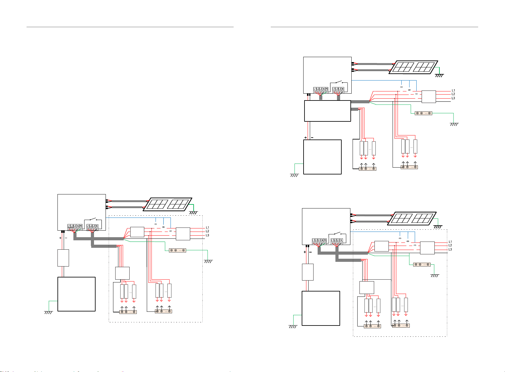
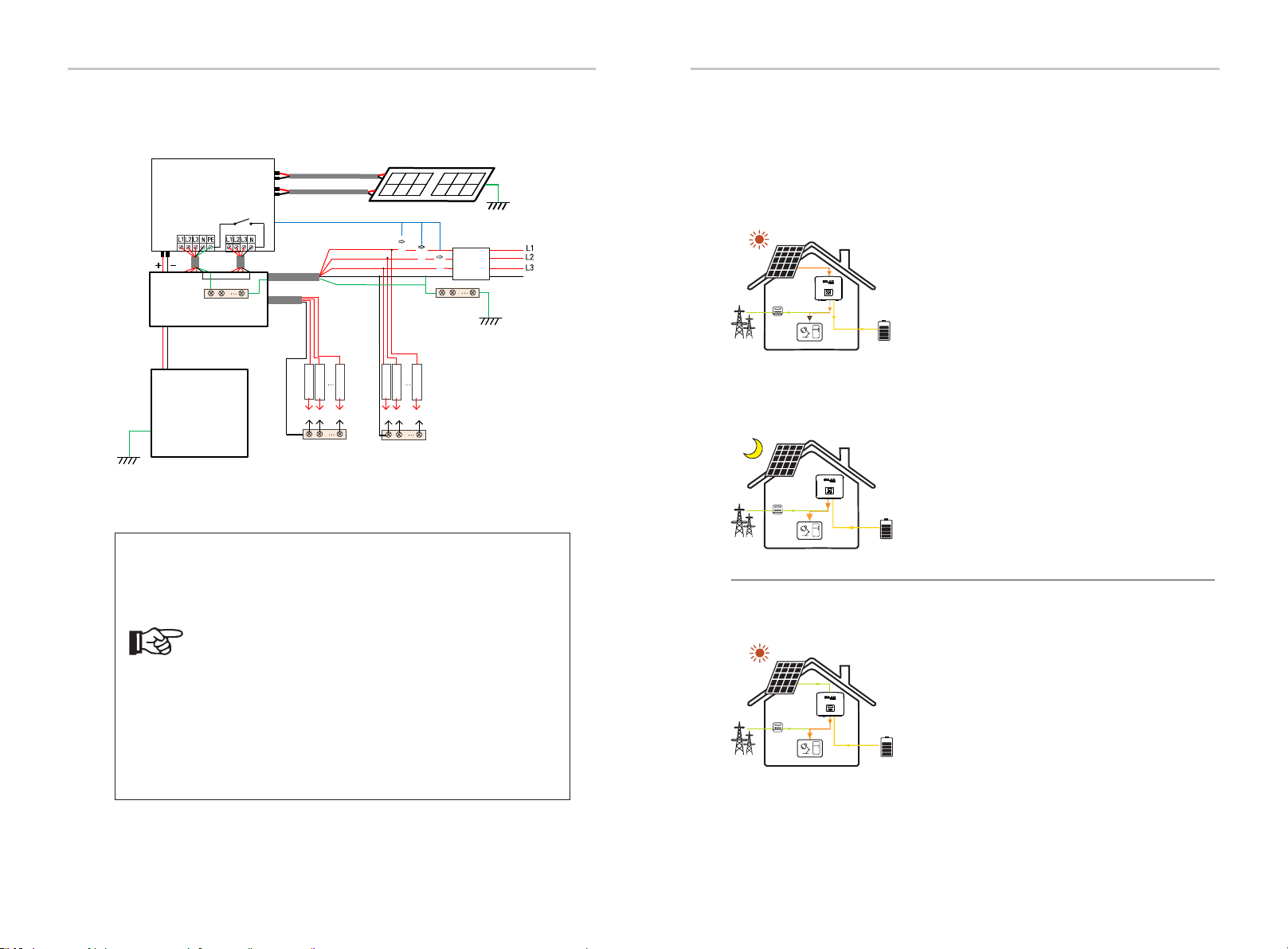
Diagram D: N line and PE line together, M series inverter;
( Applicable to Australia)
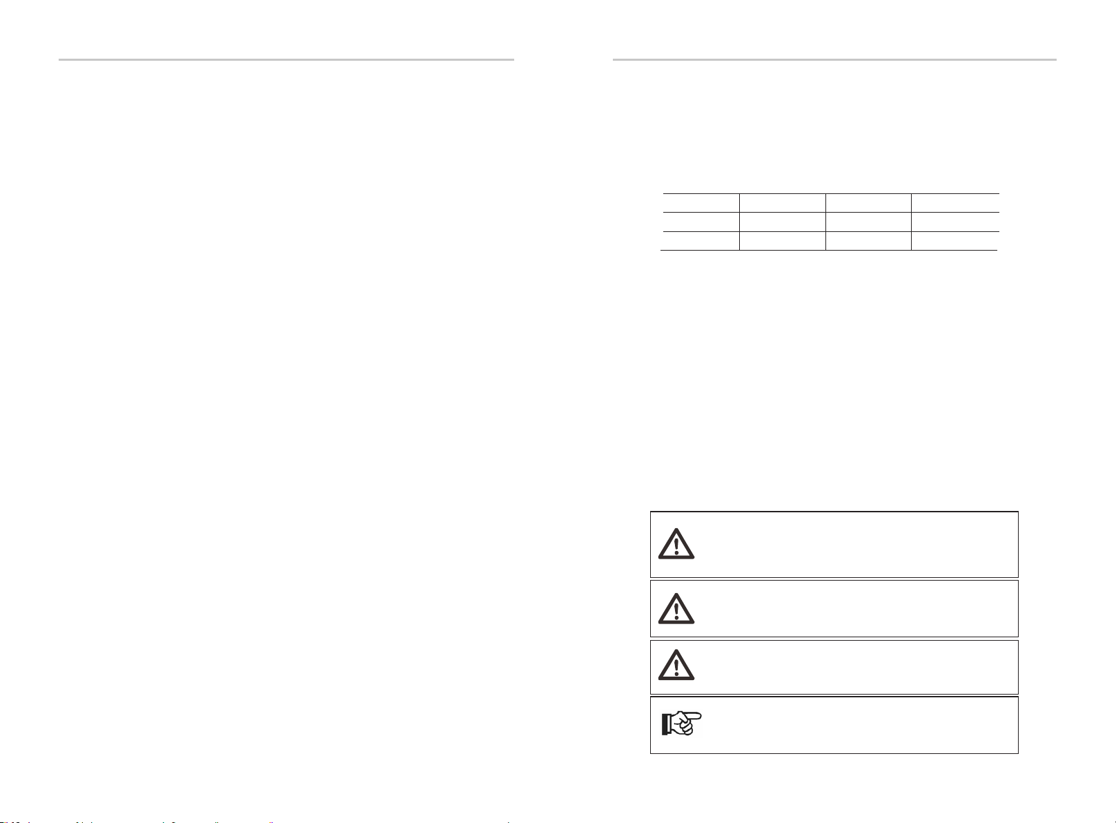
Note!
The RCD on the gure represents a leakage protection
device with a circuit breaker function.
• When power cuts suddenly, the inverter connects the N
line of EPS(Off-grid) load with the ground through relay,
providing a xed zero potential for EPS(Off-grid) load and
ensuring the safety of electricity use by users.
• Please control the inverter load and make sure it is
"output value" in "within " EPS(Off-grid) mode, otherwise
the inverter will stop and alarm overload fault".
• Please confirm with the grid operator whether there are
special regulations for grid connection.
IntroductionIntroduction
N
BAT
Battery
N-BAR for loads
N-BAR for EPS(Off-grid) loads
EPS(Off-grid) loads Loads
X3-Hybrid G4
PV 1
PV 2
E-BAR Grid
Grid EPS(Off-grid)
Main Breaker/RCD
Breaker
Breaker
CT
CT 1
CT 2
CT 3
X3-Matebox
E-BAR
N
14 15
2.3 Work Modes
X3-Hybrid G4 series, can be based on different needs, there are a variety of models.
Self Use
The self-use mode is suitable for areas with low feed-in
subsidies and high electricity prices.
① When the power of PV is sufficient
Active Charging or Discharge time period: PV will power the
loads rstly, and surplus power will charge to the battery.
If the battery is fully charged, then sell the surplus power to
the grid;( The inverter will limit the output if Feed-in limit or
zero feed-in is needed )
(PV>Load, PV →Load→Battery → Grid)
② When the power of PV is insufficient
Active Charging time period: PV will power the loads rstly ,
the remaining power will be taken from the grid , the battery
will not discharge at this time.
(PV<Load, PV + Grid → Load)
Active Discharge time period: PV+BAT will power the loads
together. If the power is still not enough, the remaining
power will be taken from the grid.
(PV<Load, PV + Battery + Grid → Load)
③ Without PV power
Active Charging time period: The grid supplies the loads
and also can charge the battery;
(PV=0, Grid → Load + Battery)
Active Discharge time period: The battery will power the
home loads rstly. If the battery power is not enough ,the
remaining power will be taken from the grid. The inverter
will enter into the standby state.
(PV=0, Battery+Grid → Load )
Battery min SOC can be set: 10%-100%;
Charge battery to min SOC can be set:10%-100%.
Feed-in priority
①
②
①
②
③
①
②
③
The Feed-in priority mode is suitable for areas with high
feed-in subsidies, but has feed-in power limitation.
①When the power of PV is sufficient
Active Charging time period: First, PV supply power to the
load, then charge the battery to the set capacity, and then
sell the power to the grid. If the local grid company limits
the grid-connected power of the inverter, the excess energy
continues to charge the battery.
(PV> Load, PV → Load → Battery→ Grid → Battery)
Active Discharge time period: PV will power the loads rstly,
and surplus power will feed-in to the grid.
(PV> Load, PV → Load → Grid )
②When the power of PV is insufficient
Active Charging time period: PV will power the loads rstly,
the remaining power will be taken from the grid. The battery
will not discharge.
(PV< Load, PV + Grid → Load)
Discharge time period: PV+BAT will power the loads together.
If the power is still not enough, the remaining power will be
taken from the grid.
(PV< Load, PV + Battery + Grid → Load)