Westell RMM-1400/RMC-700 Manual

07/15/2015 1
Westell Troubleshooting Procedures
–Network
–Device Software
–Modules & Application Network Elements
–Power
–RMM-1400 Enclosure
–RMC-700 Enclosure
–Generator Controller Connections
–AWL Controller Connections
–Discrete Inputs
–Appendix
–Data required by Westell Tech Support
–Westell Documentation List
–Local Access Procedure
–PuTTY Configuration and Logging
–RMM/RMC SIM card installation
Prior to performing RMM-1400/RMC-700 troubleshooting procedures complete the following steps to
view the Site or Site Network Element (NE) alarm history –
Navigate to the site in Optima
oVia Search Filter method
on Optima Event View Left-click on Search Filter bar
Enter either Site number or name (partial entry will work) in the NE Name box
Left-click on the Search button
Results will appear in the NE List box
Left-click on Site Name or specific Site NE
Uncheck Most Recent box and check Include Cleared box
oVia Event method
Right-click on an Event View entry
Left-click on Open NE Tree to Source NE
NE Tree will open and source NE will be highlighted
Left-click on Site name or specific Site NE
Uncheck Most Recent box, check Include Cleared box
oReview Optima alarm history
oWhen finished uncheck Cleared box and check Most Recent box
Navigate to the site in ATC’s Footprints system and review alarm history
Confirm that there have been no revisions (hardware, systems, or software) to the devices
being monitored at the site

07/15/2015 2
NOTE: Command Line Interface (CLI) commands are displayed in the following font and format:
command sub-command user_supplied, where the user supplied information is taken from
the output of a previous command, a known good example, or from other documentation and/or
procedures
Network
Site accessible
1. For either an SNMP is down, serial modem is down, or Restore point incomplete event first
verify the SNMP settings associated to the NE
NOTE: These alarms represent situations where Optima is unable to communicate with the
RMM/RMC. Optima tries multiple times to connect with the RMM/RMC, make sure to confirm
the duration of the event using the Event View Duration column or by click on the information
icon to verify the events alarm creation
a. On Optima right-click on the site’s Remote NE to open the NE Shortcut menu, left-click
on View NE Details Connectivity tab and confirm settings
i. If settings are different than the above screen capture, enter the correct values
and click on the Update button
ii. If the settings are correct as shown resubmit this page by changing the SNMP
timeout value to 5001, then click on the Update button

07/15/2015 3
b. Launch an SSH session to site device and execute the show snmp summary
command:
i. Host addresses:
Tower East 01 - 172.20.6.14
Tower East 02 - 172.20.6.30
Tower Central 01 - 172.20.6.50
Tower Central 02 - 172.20.6.31
Tower Mountain - 172.20.6.51
Tower Pacific - 172.20.6.52
DAS –172.20.6.17
ii. Community strings
readwrite –administrator
readonly –public
c. ping the appropriate host address to confirm the site device can communicate with
Optima
d. Verify the Restore point by right clicking on the site’s Remote NE, selecting View NE
Details and checking the Software Restore Points tab for a valid restore point
(designated by a green status indicator for the most recent restore point)
e. Check Optima to see if the events in question have cleared
Site not accessible
Follow these steps for Element is Down events:
Initial Triage:
1. Using the DOS Command Prompt, send a constant ping to the RMM/RMC for at least 15
minutes (use Ctrl-C to stop)
a. ping -t 10.4X.XXX.XXX
b. If the ping response is Request Timed Out, this indicates that the network knows how
to route the IP traffic destined for this IP address (i.e. the ping to the RMM/RMC), but
the device is not responding
i. This may be due to a loss of power to the RMM/RMC or a loss of network
connectivity for LESS than 18 hours
c. If the ping response is TTL Expired in Transit, this indicates that the network does not
know how to route this traffic, causing the ping packet (ICMP packet) to go into a
routing loop for 30 hops and then returns this response
i. This may be due to a loss of power to the RMM/RMC or a loss of network
connectivity for MORE than 18 hours
d. Use the tracert 10.4X.XXX.XXX to check network routing to the remote site
i. If no route contact network engineering group to validate findings and assist
further before dispatching to site

07/15/2015 4
2. In you cannot ping or trace the route, you will want to dispatch an ATC FOT
a. Create a ticket per the Westell Ticket Process, and create an ETA ticket to dispatch an
ATC FOT to the site to investigate further.
b. For the Request Timed Out response, wait at least 4 hours to create a ticket UNLESS
there are other alarms indicating a power failure at the site. Then call the power
company to verify a power outage in the area.
Triage with Tech onsite:
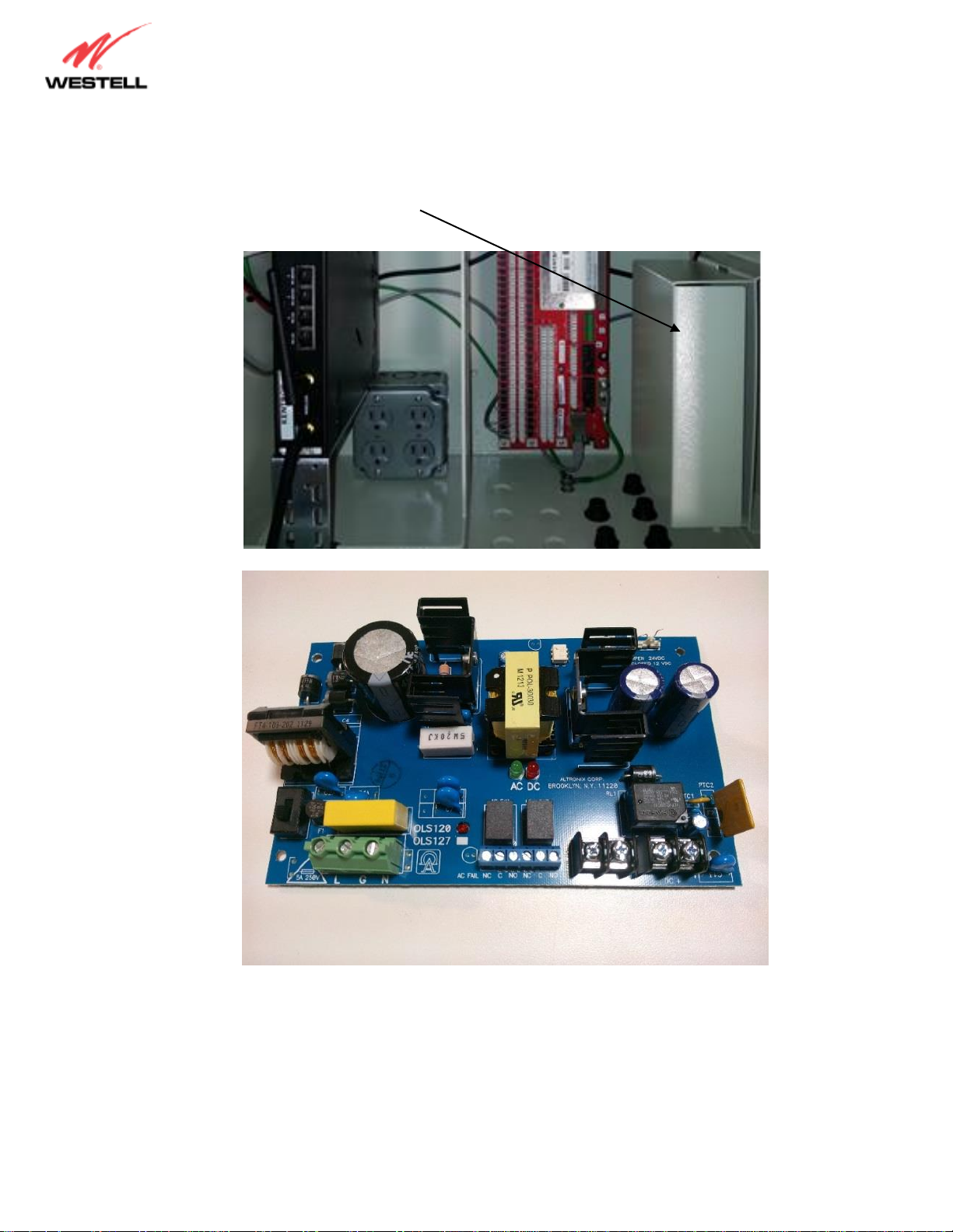
1. With an ATC FOT on site, verify the RMM/RMC has power to the unit (DC led green); if not lit
proceed to Power Troubleshooting procedure, if lit continue below:
a. Verify the red FLT led is not lit or blinking (it may stay lit for up to 5 minutes after the
RMM/RMC has been rebooted)
i. If the light is solid or blinking, it means the unit failed to boot-up properly
ii. Reboot the RMM/RMC by removing the green phoenix connector for a
minimum of 1-2 minutes
iii. After reboot, if the led remains lit after 5 minutes, follow the RMA and
Warranty Process to replace the RMM/RMC.
2. After the reboot if the FLT light is not lit red, send a constant ping to the IP address for the
RMM/RMC for at least 5 minutes
3. If connectivity is still not restored, have the tech access the device using the Local Access
Procedure
a. Once connected the Tech should enter the show meas-table entry modemMonitor,
show controller serial modem diagnostics, and show interfaces commands and
annotate the results in the ticket
b. If the signal-strength message is "Disable Controller to view signal Strength", have the
tech verify the SIM card is seated correct on the inside of the RMM/RMC. See
RMM/RMC SIM card installation instructions for more info. If it is seated correctly and
the issue remains, follow the RMA process
c. If the signal-strength is too low (2.0 or lower) moving the antenna location may gain
enough signal to move it out of the extremely low range or connecting the antenna to
the “Diversity” side will occasionally improve signal strength (although this would
indicate an internal wiring issue on the modem)
d. If the signal remains very low have the tech escalate to have an external hi-gain antenna
installed at the site
i. These should be caught by the integration team prior to NOC integration. If the
site has been accepted and there are notes indicating the signal strength was
good during commissioning, then the wireless modem in the RMM/RMC may be
bad; escalate to NOC Floor Lead for assistance (see Weak Signal Antenna Kit
MOP for details)

07/15/2015 5
e. If the signal-strength is good
ii. Enter the show controller serial modem command to check the link
state:
1. Link-State=up means the unit is connected to the network
2. Link-State=down means the RMM/RMC is not connected to the
network. This typically occurs when the unit has not been connected to
the network for an extended period of time. Run through the process to
Send Cancel Location again.
a. Log into Jasper Wireless with username atcnoc and password
Am3r1can
b. Click on Real-time Diagnostics
c. Go to the ATT SIM ID Sheet and look up the ICCID based on the
IP Address of the RMM/RMC
d. Click on the ICCID, then click on Spotlight
e. Have the tech power off the RMM/RMC and leave it powered
off for 5 minutes
f. In the Jasper Wireless Portal, hit Send Cancel Location
g. After 5 minutes, power the RMM/RMC back up; it will typically
take another 5 minutes after it's booted back up for
connectivity to restore to the unit
f. If still not able to connect to the RMM/RMC have the tech open WinSCP (see Local
Access Procedure for download instructions)
i. When WinSCP is open use 192.168.1.1 for the HOSTNAME
ii. User name: ATCUSA, password: ATCUSA
iii. After log in through the SFTP connection, click on the Remote device’s log folder
iv. Copy the logd.log file to the desktop, rename it with the Site ID and Site Name
v. Email the logd file to [email protected] asking them to review the logd file
to determine the next step for troubleshooting (i.e. ATT Network Issue or
equipment failure)
NOTE: Make sure to have the tech run the command show controller
serial modem diagnostics while logged into the RMM/RMC; copy and
send the results as well to Westell Tech Support for analyses
vi. If Westell recommends to replace the RMM/RMC, follow the RMA and
Warranty Process
vii. If Westell advises of an issue with the wireless carrier network, engage the TS to
have the ATT RMM/RMC replaced with a VZW unit due to the issues with
connectivity in the area

07/15/2015 6
Device Software
Site accessible
1. Launch an ssh session to site device and run show version command to confirm that device
is running the correct firmware and bootloader versions (look at a known good site to find latest
versions, make sure to select a site with the same hardware as there are differences between
the RMM and RMC)
a. If not running the latest versions, follow ATC procedures to upgrade the device
2. To check the RMB-1’s firmware version enter the command show peripherals unit 1
(look at a known good site to find latest version)
a. If not running the latest version, follow ATC procedures to upgrade the device
Site not accessible, Tech on-site
1. Follow Network Tech on Site procedure to restore remote access
2. Verify version as shown above and upgrade if required
Modules & Application Network Elements (NE)
Site accessible
1. A Module Tower is available for upgrade event will display on Optima if a site’s module needs
to be upgraded
a. Right-click on the event, a short cut menu will appear, Left-click on Open NE Tree to
source NE
b. Right-click on the Site NE (not the Remote NE) to open the NE Shortcut menu
c. Left-click on View NE Details and then select the Modules tab
d. Left-click on the Install Module button at the bottom of the window
e. Left-click on the checkbox next to Module and then on the Install button
f. Close the Module window, the update will proceed (may take up to 5 minutes
depending on connection stability and signal strength)
g. If the update fails log into the Remote and run the exec site uninstall *
command
i. Return to Optima and repeat steps b–f immediately
2. If a specific application or network element (NE) is not responding or reporting alarms or
measurements follow these steps to confirm the configuration

07/15/2015 7
a. Run the show site network-elements command to view configured network
elements (a type will be displayed) and state (online or offline)
i. If offline, run the show site network-elements NE_name command
to view the configuration parameters
ii. look for parameters that are blank or display a ?
iii. fill in missing parameters as required (if needed check a known good NE of the
same type for the correct parameter settings)
iv. enter the copy running-config startup-config command to save
the settings
b. re-run the show site network-elements to verify the NE is online
Site not accessible, Tech on-site
1. Follow Network Tech on Site procedure to restore remote access
2. Verify module version and application/network element as shown above, upgrade or correct as
shown
Power
RMM-1400 Enclosure -
Site accessible
1. Launch an ssh session to the site device and run show discrete analog command to
confirm the device powering
a. Correct power and wiring displays the following results:
RMM-1400
ID State Resource State Value Mode Interval Description
0/power enable assigned 26.4 V voltage 5 Battery inp
0/powerB disable unassigned 0.0 V voltage 0
b. Any other results mean the following:
i. No value for 0/power and voltage displayed for 0/powerB indicates that the
RMM/RMC’s power was incorrectly wired
ii. Voltage reading around 56 VDC on 0/powerB indicates POE and power supply
are both wired to the same input on the RMM’s green power connector
iii. Voltage reading below 24 volts indicates that the power supply potentiometer
needs to be adjusted or that the power supply may be faulty
2. If any of the non-correct results are displayed
a. Create a ticket per the Westell Ticket Process
b. Create an ETA ticket to dispatch an ATC FOT to the site to investigate further
Tech on-site
Have the tech verify that the RMM-1400 is powered by checking the DC LED is lit green
If not have the tech follow the steps below based on the enclosure type:
1. Using a meter verify that there is 115 - 120 V at the AC outlet located at the lower left of the
enclosure
a. If not check the breaker in the generator ATS or the Breaker Junction box fed by the ATS

07/15/2015 8
2. If AC power is good have the tech check the fuses on the RMM/RMC and battery feeds
a. The fuses are standard 5 AMP mini blade type (tan)
3. If the fuses are good remove the cover on the lower right side of the enclosure to reveal the
power supply.
Altronix OLS120

07/15/2015 9
Top
Front
Bottom
Front
12/24 VDC
Jumper
Potentiometer
AC/DC Status
LEDs
On/Off
Switch
AC
Power
Input
DC
Power
Ouputs
Alarm
Outputs
4. There are 2 LEDs on the board, AC (green) and DC (red). Both should be lit to indicate that
power is good. They are a little hard to see, it is helpful to use a small mirror.
5. Confirm that the On/Off slide button (bottom front of the board) is in the On (lower) position
6. Using a meter verify that there is 120 VAC across the power wires White/Black power input
(bottom front of board).
7. Verify that there is 24 - 27 VDC on both pairs of Red/Black wire (-BAT+, -DC+) connectors (top
front of the board).
8. There is a small potentiometer on the top rear of the power supply board used to adjust the DC
voltage output. If this drops below the battery voltage, it can cause an alarm. Use a small
screwdriver to adjust and meter the –DC+ output to verify that it is increasing when the
adjustment is made. This should be set as high as it goes, or stop at 27 VDC.
9. If the reading is 12 VDC the jumper next to the potentiometer needs to be opened.
10. Test continuity on the alarm wires from input 1/1 of the RMB to the connector on the Power
Supply. Start at the RMB as it is the first pair on the bottom.
11. If everything tests okay, try to re-punch the wires on the RMB, sometimes they come loose.
They can also be pulled off and then punch a jumper across the input 1/1 to see if the alarm
goes away
12. At this point if no definitive issue causing the power outage has been found, engage Westell
Support via phone (800-377-8766 option 1)
a. If they request that an RMA request be submitted for the PSU, follow the RMA and
Warranty Process
b. Update the ticket with all the steps completed with the tech onsite and set the status of
the GNOC ticket to Deferred; advise the FOT to Suspend their ETA ticket until they get
the replacement PSU

07/15/2015 10
RMC-700 Enclosure –
Site accessible
1. Launch an SSH session to the site device and run the show discrete analog command
to confirm device powering
a. Correct power and wiring displays the following results:
RMC-700
ID State Resource State Value Mode Interval Description
0/power disable unassigned 26.4 V voltage 0
0/powerB enable assigned 26.2 V voltage 5 Battery inp
b. Any other results mean the following:
i. no value for 0/power and voltage displayed for 0/powerB indicates that the
RMC’s power was incorrectly wired
ii. Voltage reading below 24 volts indicates that the power supply potentiometer
needs to be adjusted or that the power supply may be faulty
2. If any of the non-correct results are displayed
a. Create a ticket per the Westell Ticket Process
b. Create an ETA ticket to dispatch an ATC FOT to the site to investigate further

07/15/2015 11
DCOutput
ACInput
Potentiometer
DCLED
Mean Well MDR20-24
3. The power supply’s DC OK LED should be lit green
4. Using a meter verify that there is 115 - 120 V across AC power input (bottom front connectors)
5. If not check the breaker in the generator ATS or the Breaker Junction box fed by the ATS
6. If AC power is good have the tech check the fuses on the RMC and battery feeds
7. The fuses are standard 5 AMP mini blade type (tan)
8. Verify that there is 24 –26.4 VDC across the DC output (top front connectors).
9. There is a small potentiometer on the middle front of the power supply board used to adjust the
DC voltage output. Use a small screwdriver to adjust and meter the DC output to verify that it is
increasing when the adjustment is made. This should be set as high as it goes, 26.4 VDC.
10. At this point if no definitive issue causing the power outage has been found engage Westell
Support via phone (800-377-8766 option 1)
11. If requested submit an RMA request for the PSU, follow the RMA and Warranty Process
12. Update the ticket with all the steps completed with the tech onsite and set the status of the
GNOC ticket to Deferred; advise the tech to Suspend their ETA ticket until the replacement PSU
is received

07/15/2015 12
Generator Connections
Site Accessible
Follow these steps to remotely troubleshoot serial port down, communication failures, or missing data
(follow ATC or other vendor procedures for specific generator alarms):
1. Launch an ssh session to the site device and enter the command show controllers
serial Xto verify that the serial port is enabled and correctly configured
a. Serial port assignments on the RMM-1400 are:
Generac H100 & H100 HTS –RS232/Modbus (RMM-1400 & RMC-700 port 1)
b. If not enabled enter the command config controllers serial X enable
2. To verify communication on a serial port enter the command diag line-monitor
serial-X.
a. Type the letter m (will not display), then hit the Enter key to start the diagnostic session
b. Normal, showing data is being transmitted [seria-1]T> and received [seria-1]R<
c. If data is only being transmitted the controller is not responding due to a disconnected
or bad cable or a controller or software issue any of which will require a site visit
d. Use Ctrl-c to stop the diagnostic process
e. If a site visit is required
i. Create a ticket per the Westell Ticket Process
ii. Create an ETA ticket to dispatch an ATC FOT to the site to investigate further
3. If communication is good, verify that measurement values are being reported enter the
command show meas-table entries
4. For details (state, originator, NE Name, and values) of a specific measurement by entering the
command show meas-table entries measurement_name
5. If the measurement is offline do the following:
a. For measurements that are configured by the module (will show as dynamic or
originated by a script):
i. Enter the command show site network-elements NE_Name to
confirm that the network element is online and configured correctly
NOTE: Verify the NE type is correct for the system being monitored, if not the site
network element will need to be reconfigured for the correct system
ii. If the NE state is offline check to make sure that none of the parameters is
displaying a question mark (?) in the value field, if so a correct value needs to be
entered using the command config site network-element
cabinetDoor param Parameter_Name Value (look at a known good
site to find the correct values)
b. For measurements that are manually configured (will show as static and not
originated by a script):
c. Confirm the originator is enabled using the command show discrete
analogs, if not enter the command config discrete analog X/X
enable
6. At this point if no definitive issue causing the problem has been found, engage Westell Support
via phone (800-377-8766 option 1)

07/15/2015 13
Tech on site
1. Have the tech confirm that the controller is operational
2. Have the tech check that the cable is firmly connected at the RMM/RMC and at the controller
a. Have the tech re-connect the cable at both ends and verify correct pin outs with cable
tester; verify all the way through DB-9 adapter, if applicable
b. If there is no communication, if possible have the tech replace the cable and DB-9
adapter
3. If a good connection (communication failure clears) still does not occur have the Tech move the
cable to an unused serial port on the RMM-1400 (this step is not possible on the RMC-700)
Generac H100 & H100 HTS –RS232/Modbus (RMM-1400 port 2)
4. On the RMM-1400 enter the show run command and locate the configuration for the serial
port being re-homed
a. Update the parameter with the new serial using the following command
config site network-element NE_name param controller serial X
(where NE_name is taken from results of show run command and serial port is the
value of the re-homed serial port)
config site network-element generator
type GeneracH100HTSGenerator
param controller 'serial 2'
b. Enter the copy running-config startup-config command to save the
configuration
5. If the connection does not go online engage Westell Support via phone (800-377-8766 option 1)
c. If requested submit an RMA request for the RMM/RMC, 3follow the RMA and Warranty
Process

07/15/2015 14
AWL Controller Connections
Site Accessible
Follow these steps to remotely troubleshoot serial port down, communication failures, or missing data
(follow ATC or other vendor procedures for specific AWL alarms):
1. Launch an ssh session to the site device and enter the command show controllers
serial Xto verify that the serial port is enabled and correctly configured
a. Serial port assignments on the RMM-1400 are:
i. Dialight Medium Intensity –RS485/Modbus (RMM-1400 port 3, RMC- 700 port
2)
ii. Flash Eagle 11 –RS232/ASCII (RMM-1400 serial port 2, RMC-700 port 1 (if no
generator))
iii. Flash LED –RS485/Modbus (RMM-1400 serial port 3, RMC-700 port 2)
iv. Flash Vanguard –RS485/Modbus (RMM-1400 serial port 3, RMC-700 port 2)
b. If not enabled enter the command config controllers serial X enable
2. To verify communication on a serial port enter the command diag line-monitor
serial-X.
a. Type the letter m (will not display), then hit the Enter key to start the diagnostic session
b. Normal, showing data is being transmitted [seria-1]T> and received [seria-1]R<
c. If data is only being transmitted the controller is not responding due to a disconnected
or bad cable or a controller or software issue any of which will require a site visit
d. Enter (ctrl)+c to stop the diagnostic process
e. If a site visit is required
i. Create a ticket per the Westell Ticket Process
ii. Create an ETA ticket to dispatch an ATC FOT to the site to investigate further
3. If the system is an ethernet Flash Vanguard, it should be connected via ethernet port 4 on the
RMM-1400 or ethernet 2 on the RMC-700
a. To verify the ethernet port is enabled enter the command show controllers
ethernet X
b. If not enter the command config controllers ethernet Xenable
c. To verify communication on the ethernet port enter the command show
interfaces bridge switch the results will display a list of the ethernet ports
with transmit (Tx) and receive (Rx) stats; repeat the command two or three times to see
if both values increase
d. If there is no two-way communication a site visit is required
i. Create a ticket per the Westell Ticket Process
ii. Create an ETA ticket to dispatch an ATC FOT to the site to investigate further
4. If communication is good, to verify that measurement values are being reported enter the
command show meas-table entries
5. For details (state, originator, NE Name, and values) of a specific measurement enter the
command show meas-table entries measurement_name

07/15/2015 15
6. If the measurement is offline do the following:
a. For measurements that are configured by the module (will show as dynamic or
originated by a script):
i. Enter the command show site network-elements NE_Name to
confirm that the network element is online and configured correctly
NOTE: Verify the NE type is correct for the system being monitored, if not the site
network element will need to be reconfigured for the correct system
ii. If the NE state is offline check to make sure that none of the parameters is
displaying a question mark (?) in the value field, if so a correct value needs to be
entered using the command config site network-element
cabinetDoor param Parameter_Name Value (look at a known good
site to find the correct values)
b. For measurements that are manually configured (will show as static and not
originated by a script):
i. Confirm the originator is enabled using the command show discrete
analogs
1. If not enter the command config discrete analog X/X
enable
7. At this point if no definitive issue causing the problem has been found, engage Westell Support
via phone (800-377-8766 option 1)
Tech on site
1. Have the tech confirm that the controller is operational
2. Have the tech check that the cable is firmly connected at the RMM/RMC and at the controller
a. Have the tech re-connect the cable at both ends and verify correct pin outs with cable
tester; verify all the way through DB-9 adapter, if applicable
b. If there is no communication, if possible have the tech replace the cable and DB-9
adapter
3. If a good connection (communication failure clears) still does not occur have the Tech move the
cable to and unused port on the RMM-1400 (this step is not possible on the RMC-700)
a. Dialight Medium Intensity or Flash LED –RS485/Modbus (RMM-1400 port 4)
b. Flash Eagle 11 –RS232/ASCII (RMM-1400 serial port 1 (if no generator))
c. Flash Vanguard –RS485/Modbus (RMM-1400 serial port 4 or ethernet port 3)
4. On the RMM enter the show run command and locate the configuration for the serial port
being re-homed
a. Update the parameter with the new serial using the following command
b. config site network-element NE_name param controller serial X
i. (where NE_name is taken from results of show run command and serial port is
the value of the re-homed serial port)
config site network-element towerLight
type FlashVanguardSerialDiscreteTowerLight
param controller 'serial 4'
c. Enter the copy running-config startup-config command to save the
configuration
5. If the connection does not go online engage Westell Support via phone (800-377-8766 option 1)
a. If requested submit an RMA request for the RMM/RMC, follow the RMA and Warranty
Process

07/15/2015 16
Discrete Inputs
Site accessible
Follow these steps to remotely verify and troubleshoot alarms based on discrete (dry contact) inputs:
1. Launch an ssh session to the site device and enter the show alarm-entry command to
confirm alarm status on the RMM/RMC
2. Enter the show alarm-entry name alarm_name (for the alarm being investigated)
command to view details of the alarm; including the originator (discrete input that the alarm is
wired to) and that the Trap is enabled
3. Using the Enter the command show discrete inputs X/X (from originator field in step
2 results) to verify input is enabled and current value (open or close)
4. To test the alarm enter the command
a. diag test alarm-entry alarm_name mode normal 2 –this command
should clear the event for two minutes
b. To simulate a non-normal alarm enter the command
i. diag test alarm-entry alarm_name mode non-normal 2 –
this command should clear the event for two minutes
5. If the test commands do not cause events on Optima use the following steps to view the
RMM/RMC’s trap log
a. Enter the command debug snmp traplog enable
b. Enter the command diag test alarm-entry alarm_name mode normal
c. The trap information should display as follows:
20150226:092855:-0500: Send trap to: 172.20.6.14:162:administrator:v1
Trap OID: .1.3.6.1.4.1.539.42.2.0.4(majorAlarmTrap)
Varbind: .1.3.6.1.4.1.539.42.2.2.1.1(aiMediationAlarmIndex) = 1
Varbind: .1.3.6.1.4.1.539.42.2.2.1.7(aiMediationAlarmName) = TestAlarm1
Varbind: .1.3.6.1.4.1.539.42.2.2.1.5(aiMediationAlarmMessage) =
TestAlarm1 Alarm
Varbind: .1.3.6.1.4.1.539.8.2.0(aiSystemLastTrapSequenceNum) = 30
Varbind: .1.3.6.1.4.1.539.42.2.2.1.9(aiMediationAlarmCategory) =
Varbind: .1.3.6.1.4.1.539.42.2.2.1.10(aiMediationAlarmNeName) =
Varbind: .1.3.6.1.4.1.539.42.2.3(aiMediationTestMode) = 1
Varbind: .1.3.6.1.4.1.539.8.15.0(aiSystemTrapCreationTime) = 2015-2-
26,9:28:55.6,-5:0
The information displayed includes the snmp host and community string, alarm severity,
alarm name, and description; it is save in the logd.log file
d. If the information displayed is correct follow the Network-Site Accessible procedure to
verify Optima and RMM/RMC device SNMP settings
e. Enter the command debug snmp traplog disable stop the trap log display
6. If all discrete based alarm events display as non-normal (or a Peripheral units not connected:1
event is received) confirm the RMB-1 is online with the command show peripherals
a. The correct results are:
Name State IP Manager IP Manager Name
--------------------------------------------------------------------------
RMB1-10250C Online N/A 10.48.100.225 TrainRMM
Unit Name IP Description
--------------------------------------------------------------------------
1 RMB1-10250C N/A

07/15/2015 17
b. If the results show that the RMB-1’s state as Unmanaged enter the command config
peripheral 1 manage RMB-1_Name (from show peripherals command
result)
i. Wait two minutes then enter show peripherals command
ii. If the results show the RMB-1’s state as AdminManaged verify that ethernet port
1 is enabled with the link-state is up of using the show controllers
ethernet 1 command
1. If state is disabled and link-state is down enter config
controllers ethernet 1 enable command
2. Re-enter the show controllers ethernet 1 command
a. If the link is still off-line a site visit is required
c. If the results display an RMB-1 name for Unit 1, but that name is not displayed under
the Name column a site visit is required
Name State IP Manager IP Manager Name
--------------------------------------------------------------------------
Unit Name IP Description
--------------------------------------------------------------------------
1RMB1-10250C
d. If a site visit is required
i. Create a ticket per the Westell Ticket Process
ii. Create an ETA ticket to dispatch an ATC FOT to the site to investigate further
Tech on site
For RMB-1 issues:
1. Have the tech verify that the ethernet cable is connected from the RMM’s ethernet port 1 to
the RMB-1 and that that the link LED on both units are lit green (the upper left corner on each
RMM ethernet port)
a. If the cable is not connected have the tech do so and re-check LEDs
i. If the LEDs do not light up have the tech connect the cable to the RMM’s
ethernet port 2 and re-check the LEDs
1. If this corrects the problem update the site information to show the
RMB-1 connected to ethernet port 2
ii. If the LEDs still do not light have the tech try a known good ethernet cable and
re-check the LEDs
b. If LEDs are lit launch an ssh session to the site device (if site not accessible have the tech
access the device using the Local Access Procedure) and enter the show peripherals
command to confirm it is managed and online
i. If not follow step 6 in Site Accessible procedure

07/15/2015 18
2. If the LEDs do not light up or the RMB-1 does not go online engage Westell Support via phone
(800-377-8766 option 1)
a. If requested submit an RMA request for the RMB-1, follow the RMA and Warranty
Process
b. Update the ticket with all the steps completed with the tech onsite and set the status of
the GNOC ticket to Deferred; advise the tech to Suspend their ETA ticket until the
replacement RMB-1 is received
For dry contact alarms issues that require an ATC FOT on site such as a discrete event that does not
correlate to an event generated by a generator or AWL controller
1. Enter the show alarm-entry name alarm_name (for the alarm being investigated)
command to view details of the alarm; including the originator (discrete input that the alarm is
wired to)
2. Have the tech check that the wires are firmly punched down on to the originator input on the
RMB-1 and connected to the sensor being monitored test
a. If not have the tech re-punch the wires and/or re-connect the sensor
3. Have the Tech check continuity on the alarm wires from the RMB-1 or RMC input to the sensor
to confirm the wire is not broken
a. If the continuity check fails the wire should be checked manually to locate and repair
the break or replaced
4. Repeat step 1
5. If the correct reading does not occur have the Tech pull the wires at the RMB-1 or RMC and re-
punch on an unused input
a. Verify the state of the input by entering the show discrete inputs X/X
command, where the input is the value of the re-homed input
6. On the RMM/RMC enter the show run command and locate the configuration for the input
being re-homed
config site network-element cabinetPowerDetection
type DiscretePowerDetection
param discrete 'input 1/1'
param normalState close
a. Update the parameter with the new discrete input using the following command
b. config site network-element NE_name param discrete input X/X
i. (where NE_name is taken from results of show run command and input is the
value of the re-homed input)
c. Enter the copy running-config startup-config command to save the
configuration

07/15/2015 19
Appendix
Data for Westell Tech Support
–Site number or name
–Event or alarm description
–NOC technician contact information
–Field technician contact information
–copy or log of ssh session with results of troubleshooting show, diag, and debug
commands
–copy of logd.log file
Westell Documentation list
Current versions -
–Remote RMC-700 Installation Guide
–Remote RMC-700 Version 5.3x Command Reference Guide
–Remote RMC-700 Version 5.3x Configuration Guide
–Remote RMM-1400 Installation Guide
–Remote RMM-1400 Version 5.3x Command Reference Guide
–Remote RMM-1400 Version 5.3x Configuration Guide
–Remote RMB-1 Installation Guide
The most recent versions of these documents are available at: http://support.westell.com/ in
the Documentation Library section:
A Westell Portal login is required to access these documents
To set up a login click on the Register button on the site home page and complete the process

07/15/2015 20
Local Access Procedure
A. Equipment and software needed for this procedure:
Laptop with Ethernet connection
Straight thru Ethernet cable
For ssh (CLI) use PuTTY –download at
http://the.earth.li/~sgtatham/putty/latest/x86/putty.exe
For sftp (file transfer) use WinSCP –download at
http://winscp.net/download/winscp556setup.exe
B. Connect the Ethernet cable to the laptop and to the Remote device as follows:
a. RMM1400 - Connect Ethernet cable from PC to RMM1400 Ethernet port 3
b. RMC700 –Connect Ethernet cable from PC to RMC700 Ethernet port 1
c. If correctly configured, the Remote device will provide the laptop with an IP
address
C. Open a PuTTY ssh session to IP address 192.168.1.1
a. Login as: ATCUSA, Password: ATCUSA
b. Site device name should appear as a command prompt (i.e. (WattsIA)>)
c. Proceed with troubleshooting activity
D. If the connection does not open the unit may have been reset to factory default
settings, use these steps to connect to the unit:
a. RMM-1400/RMC-700
i. Open a PuTTY ssh session to IP address 169.254.10.1 (Port 22)
ii. Login as: admin, Password: password
b. Default command prompt will appear
c. Load configuration per NIT instructions
Table of contents
Popular Measuring Instrument manuals by other brands

Leica
Leica Nova MS60 user manual

Precision Digital Corporation
Precision Digital Corporation PROVU PD6262 Series instruction manual

SKF
SKF TKST 21 Instructions for use

Kobold
Kobold DPT Series operating instructions

Apera Instruments
Apera Instruments SX721 user manual

Tanaka
Tanaka AKV-202 Maintenance manual