4
IMPORTANT SAFETY INFORMATION
Read and understand these instructions prior to use. These operating instructions
are not a substitute for proper training in the use of this equipment. High voltage
systems present serious hazards, including the risk of death or serious injury due to
arcing, thermal burns and electrocution. HD Electric’s products are intended solely
for use by professionals with knowledge, training and experience in the use of
the equipment and its accessories in and around high voltage systems.
All applicable federal, state, company and OSHA work practices
must be followed. If you are unfamiliar with the work practices
required, DO NOT PROCEED. Call HD Electric if you
have any questions regarding this equipment.
These important labels are affixed to
THE RODUCT. Read and understand
each of them before proceeding.
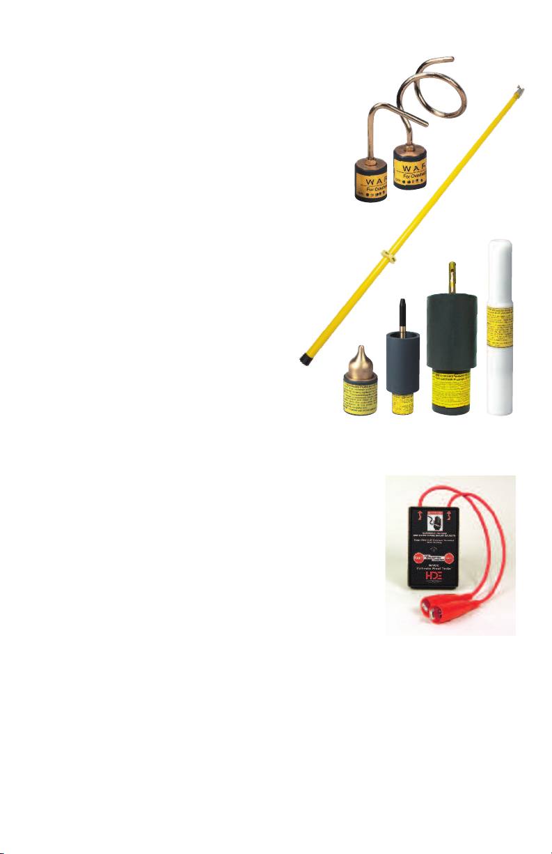
All meters require the use of accessory
hot sticks, which may or may not be
supplied with the meter. The minimum
hot stick length required for safe use depends
upon the particular operation; consult federal,
state, company and OSHA specifications for the
proper hot stick length for the intended operation.
The users of this meter should always be equipped with personal protective equipment
including high voltage gloves, flame retardant clothing, eye and face protection. Some
applications may require additional protective equipment.
Accessory probes are available for all meters. Always use the proper probe(s) for your
application.
Failure to follow these and other warnings and safety precautions may result in severe
injury or death.
OPERATIONAL IMPAIRMENT
If the DDPM-40 is used in a manner not described in this instruction manual,
the protection and effective operation of this equipment may be impaired.
07/18
USE
HOT
STICK
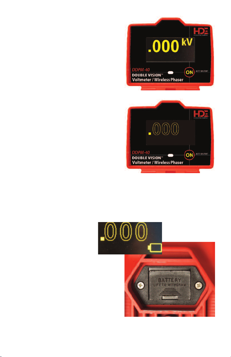
Press ON switch.
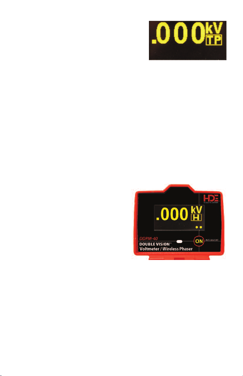
Press ON again to select
Test Point TP, Peak Hold H.
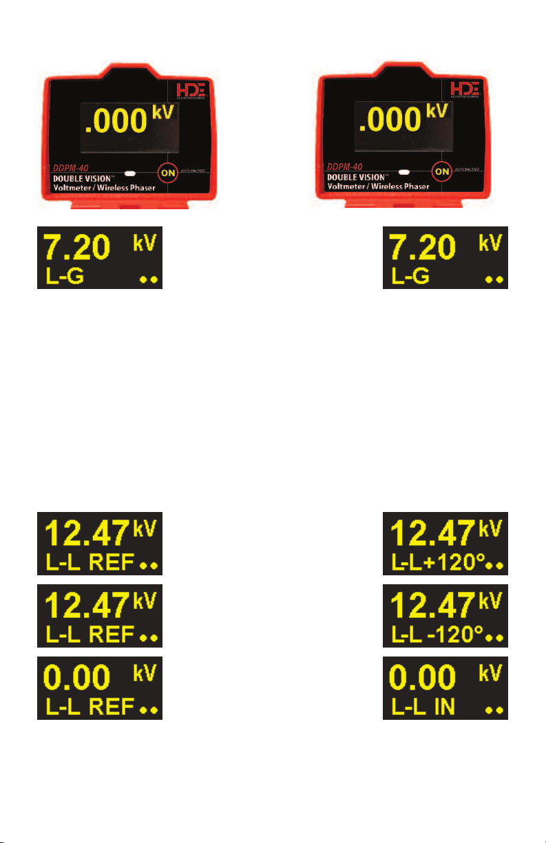
Dots in lower right corner of
display indicate active wireless
communication. See instruction
manual.
NOTICE: Use correct overhead
and underground probes. Use only
with high voltage insulating hot sticks
with length appropriate for voltage. For
use by trained high voltage professionals
only.
CAUTION: The housing is not an insulator
and must not bridge energized conductors or
an energized conductor to ground. Do not use
on voltages higher than 43kV line-to-line. Test on
known voltage source before and after each use.
Inspect connecting cord and return meter to
HD Electric Company for repair if cord or other meter
components are worn or damaged. Keep cord free and
clear of all conductors during application.
WARNING: All OSHA and company work practices must be
followed. Always wear approved insulated gloves, eye and
face protection and FR clothing. Do not touch meter housing
during measurement. Read and understand instructions. Failure
to follow these instructions or other misuse or misapplication can
lead to severe injury and death.
Part No. DDPM-40 Serial No.
www.HDE lectr i cComp any.com
www.GlobalTestSupply.com
Find Quality Products Online at: sales@GlobalTestSupply.com