Westermo LD-63B AC User manual

Linjedelare, optisk fiber
- RS-422/485
Line sharing device, fibre optic
- RS-422/485
Glasfaser Leitungsteiler
- RS-422/485
INSTALLATIONSANVISNING
INSTALLATION MANUAL
INSTALLATIONS ANLEITUNG
6072-2021
www.westermo.se
LD-63B AC
LD-63B DC
©Westermo Teleindustri AB • 2000 • Rev. C
Galvanic
Isolation Transient
Protection Balanced
Transmission CE
Approved
AUDIN - 8, avenue de la malle - 51370 Saint Brice Courcelles

10 6072-2021
Specifications LD-63B
Transmission Asynchronous, full/half duplex or simplex
Interface 1 EIA RS-422/RS-485/ CCITT V.11
5-position screw block
Interface 2 4 ST-connectors, see table of power budget
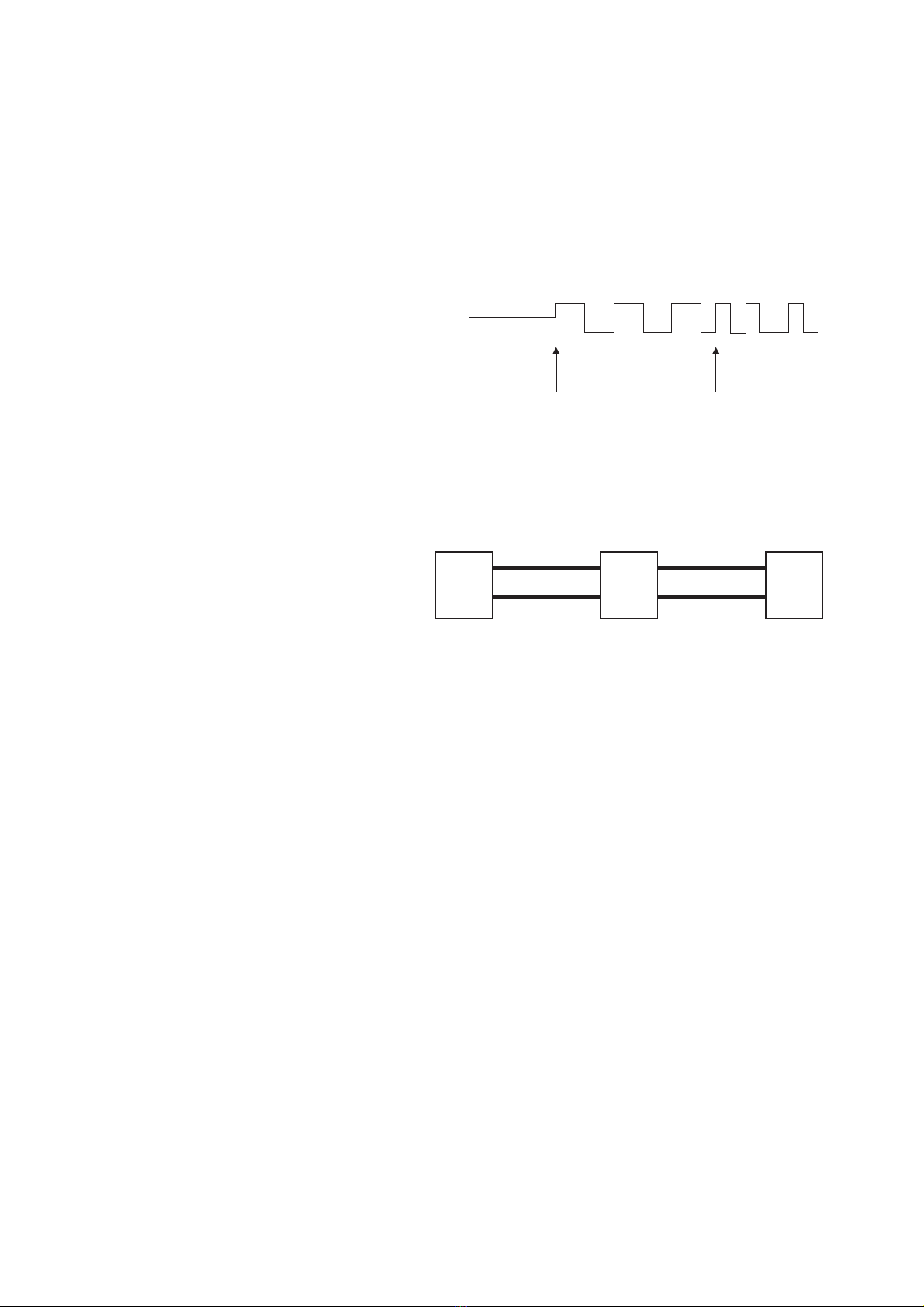
Data rate 500 kbit/s to 4Mbit/s Manchester code*
Indicators Power, TD, RD, TX1, TX2, RX1, RX2
Temperature range 5–50°C, ambient temperature
Humidity 0–95% RH without condensation
Dimension 55x100x128 mm (WxHxD)
Weight 0.6 kg
Mounting On 35 mm DIN-rail
Power supply alternatives
* For higher data rate, please contact Westermo.
Description LD-63B
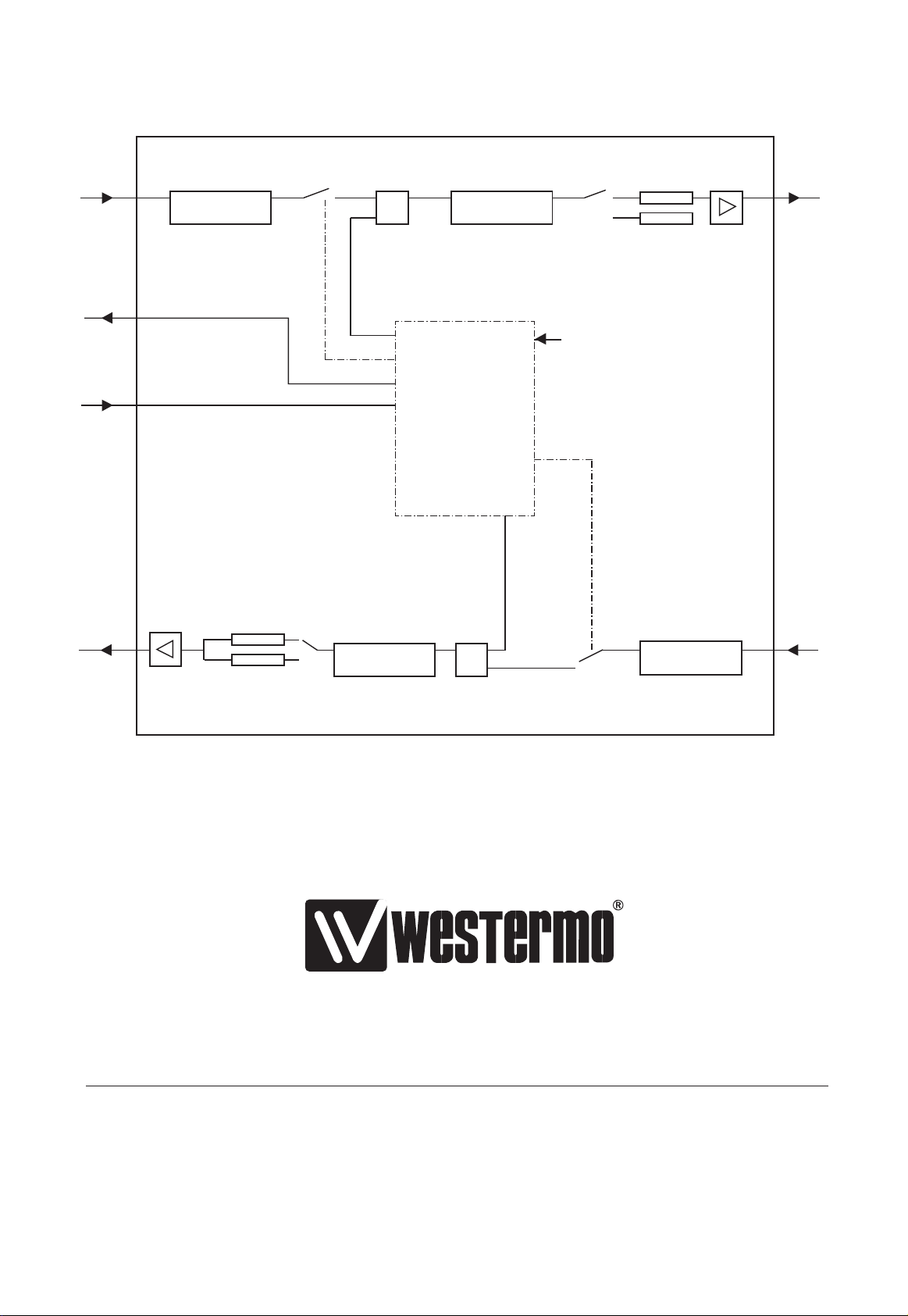
The LD-63B is a line splitter for use in multi-drop fibre optic networks. The LD-63B
allows conversion between RS-422/485 and fibre optic. LD-63B is specially developed for
Manchester coded protocols with transmission rates over 500 kbit/s. The LD-63B
consists of two F/O channels, each with its separate transmitter and receiver (TX1, TX2,
RX1 and RX2). On the front of the units there are seven LED’s indicating the datatrans-
mission on the channels. The fibre optic interface is transparent which means that data
received on RX1 is retransmitted on TX2 and data received on RX2 on TX1.
The number of LD-63B in multidrop is limited. See table of ”Maximum number of units”
on page 15.
Model description LD-63B LD-63B LD-63B LD-63B LD-63B
AC 115V AC DC 36–55V DC 110V DC
Power supply 230V AC 115V AC 24V DC 48V DC 110V DC/80V AC
+15/–10% +15/–10% +50/–50% +15/–25% +10/–10%
Frequency 48–62Hz 48–62Hz – – –/48–62Hz
Fuse, F2 100mA S 100mA S 1.6A S 1.6A S 1A T/1A T
5x20 mm 5x20 mm 5x20 mm 5x20 mm –/–
Littelfuse Littelfuse Littelfuse Littelfuse Wickmann
Power consumption 5VA 5VA 3W 3W 3W/3VA
Overvoltage
protection 430V 220V – – 430V
Isolation 1 500V 1 500V 500V 500V 3 750V
RMS
AUDIN - 8, avenue de la malle - 51370 Saint Brice Courcelles - Tel : 03.26.04.20.21 - Fax : 03.26.04.28.20 - Web : http: www.audin.fr - Email : [email protected]

116072-2021
Power budget
The LD-63B is developed for Manchester coded protocols and this means that the power
budget will change with the number of preamble bits in the actual protocol. Preamble bits
are sent before the actual data and has the function of synchronise units in the network
(see figure below).
The LD-63B uses the preamble bits for stabilising before receiving data and this means that
the LD-63B will distort the preamble bits used with more than 10%. The diagrams shows the
available power budget at different number of available preamble bits and at different trans-
mission speeds.
Observe that the diagrams state the
minimum guaranteed power budget.
Experience show however that the typical
value is about 4 dBm higher with 820 nm,
about 3,5 dBm higher with 1300 nm and about 6 dBm higher with singel mode.
Also observe that the calculated values applies between two LD-63B units. In larger networks
each fiber optical loop needs to be summated to get the number of used preamble bits.
Example:
Calculation of number of used
preamble bits.
Assume 820 nm units and 1 Mbit/s tranmission rate.
This means that fiberloop 1, which need 6 dB, will use maximum 1 preamble bit
(from diagram).
Fiberloop 2 needs 14 dB and will use maximum 10 preamble bits (from diagram).
This gives a total maximum of 11 preamble bits.
Idle line 3 preamble bits Start sending data
(Manchester coded)
LD-63B
Loop 1
6dB 14dB
Loop 2
LD-63B LD-63B
Connection:
AUDIN - 8, avenue de la malle - 51370 Saint Brice Courcelles - Tel : 03.26.04.20.21 - Fax : 03.26.04.28.20 - Web : http: www.audin.fr - Email : [email protected]

12 6072-2021
16
14
12
10
8
6
4
2
00 500 1000 1500 2000 2500 3000 3500 4000 4500
20 bits
preamble
10 bits
preamble
1 bit
preamble
2 bits
preamble
Power budget (dBm)
Transmission speed (kbit/s)
Minimum guaranteed budget 820nm, 62.5/125µm fibre
Minimum guaranteed budget 1300nm, 62.5/125µm fibre
Minimum guaranteed budget single mode, 9/125µm fibre
14
12
10
8
6
4
2
00 500 1000 1500 2000 2500 3000 3500 4000 4500
20 bits
preamble
10 bits
preamble
1 bit
preamble
2 bits
preamble
Power budget (dBm)
Transmission speed (kbit/s)
7
6
5
4
3
2
1
00 500 1000 1500 2000 2500 3000 3500 4000 4500
20 bits
preamble
10 bits
preamble
1 bit
preamble 2 bits
preamble
Power budget (dBm)
Transmission speed (kbit/s)
AUDIN - 8, avenue de la malle - 51370 Saint Brice Courcelles - Tel : 03.26.04.20.21 - Fax : 03.26.04.28.20 - Web : http: www.audin.fr - Email : [email protected]

136072-2021
LEDs for indication on LD-63B
• PWR: Indicates that the converter has power.
• TD: Indicates that the converter is receiving data on RS-422/485 side.
• RD: Indicates that the converter is sending data on RS-422/485 side.
• Rx1: Indicates received data on fiber channel 1.
• Rx2: Indicates received data on fiber channel 2.
• Tx1: Indicates that the converter is sending data on fiber channel 1 from RS-422/485 side.
• Tx2: Indicates that the converter is sending data on fiber channel 2 from RS-422/485 side.
50/125 µm 3.0 dB/km 1.0 dB/km
62.5/125 µm 3.5 dB/km 1.2 dB/km
100/140 µm 4.0 dB/km
9/125 µm 0.5 dB/km
Fibre Attenuation
at 820 nm
Attenuation
at 1300 nm
Attenuation
at single mode (1300 nm)
Attenuation in fibre cable
The values below can differ depending on quality and manufacturer of the fibre-optic
cable.
Attenuation in connectors Attenuation in splice
0.2–0.4 dB Fusion 0.1 dB
Mecanical 0.2 dB
AUDIN - 8, avenue de la malle - 51370 Saint Brice Courcelles - Tel : 03.26.04.20.21 - Fax : 03.26.04.28.20 - Web : http: www.audin.fr - Email : [email protected]

14 6072-2021
Selection of V or Y function
Y
S1
ON
123456789
V
S1
Termination with fail-safe
Termination (2wire)
S2
Termination (4wire)
S2
No termination
S2
Transmitted power channel 1
Low
S2
High
S2
Transmitted power channel 2
Low
S3: 2–4 not used.
The fail-safe function forces the signal state of the receiver
to OFF when the connected transmitter is in tri-state
(transmitter inactive). The receiver located furthest away
shall be terminated.
V-mode and Y-mode are described on page 11.
S3
High
S3
Switch settings LD-63B
ON
1234
ON
1234
123456789
S2:1-5
S1:1-9
S3:4-1
ON
12345
ON
12345
Factory settings
S1
ON
123456789
S3
ON
1234
S2
ON
12345
Selection of 2- or 4-wire
4-wire
S1
ON
123456789
2-wire
S1
Selection of 2-wire RS-485 or 4-wire RS-422.
S1: 4–9 is not used.
Selection of speed
Over 1 Mbit
S1
Under 1 Mbit
S1
ON
123456789
ON
12345
12345
ON
12345
ON
ON
123456789
ON
123456789
ON
123456789
AUDIN - 8, avenue de la malle - 51370 Saint Brice Courcelles - Tel : 03.26.04.20.21 - Fax : 03.26.04.28.20 - Web : http: www.audin.fr - Email : [email protected]

156072-2021
Screw Power
no. supply
L 115**/230V
N AC power
Earth
Connections LD-63B
Line connection
(5-position screw terminal)
Power connection
LD-63B DC
2-position screw-terminal
Direction Connection CCITT V.11
nr. Description
Receiver 1 A’ (R+)
Receiver 2 B’ (R-)
Transmitter 3 A (T+)
Transmitter 4 B (T-)
5 Shield
Connection Power
no. supply
1 – Voltage
2 + Voltage
Power connection
LD-63B AC
3-position screw-terminal
Description V/Y mode
* LD-63B 115V
12345 LN
LD-63
RS-422/485 POWER
R+
Rx1
Rx2
Tx1
Tx2
R- T+ T-
TD RDPWR
The definations R+/R–,T+/T– can be various between
different manufactures.
LA-01Y
OR
OR
OR
LA-01V
OR
F/O
V-function
channel 1 channel 2
channel 1 channel 2
Y-function
F/O
F/O F/O
RS-422/485
RS-422/485
Maximum number of units
Transmission speed Number of units
500 kbit/s 16
1 Mbit/s 8
2 Mbit/s 4
4 Mbit/s 2
For additional units please contact Westermo
AUDIN - 8, avenue de la malle - 51370 Saint Brice Courcelles - Tel : 03.26.04.20.21 - Fax : 03.26.04.28.20 - Web : http: www.audin.fr - Email : [email protected]

16 6072-2021
RS-422/485
Example: Multidrop
Connection of RS-422, RS-485
LD-63B
RX1 RX2
TX2
TX1
RX1 RX2
TX2
TX1
LD-63B LD-63B
RS-422/485 RS-422/485
RX1 RX2
TX2
TX1
12345 LN
RS-422/485 POWER
R+
Rx2
Tx1
Tx2
R- T+ T- 12345 LN
RS-422/485 POWER
R+
Rx2
Tx1
Tx2
R- T+ T-
R+
RS-422
equipment
R–
T+T–
RS-485
equipment
T+T–
*) The designations A, A’, B, B’ are sometimes use instead of T+, T–, R+, R–.
Despite the standard, different manufacturers name the signals differently.
The first step in fault finding is to reverse the cables (swap T+ with T– and/or
R+ with R–). Please note that this should be done only at one end!
**
S1:2 ON
NB When a multidrop connection ends with an LD-63B and the fibre pair
is connected on channel 2, the switch S1:2 must be set (Y-function)
Y-funktion
AUDIN - 8, avenue de la malle - 51370 Saint Brice Courcelles - Tel : 03.26.04.20.21 - Fax : 03.26.04.28.20 - Web : http: www.audin.fr - Email : [email protected]

176072-2021
OWN COMMENTS
.....................................................................................................................................................................................................................
.....................................................................................................................................................................................................................
.....................................................................................................................................................................................................................
.....................................................................................................................................................................................................................
.....................................................................................................................................................................................................................
.....................................................................................................................................................................................................................
.....................................................................................................................................................................................................................
.....................................................................................................................................................................................................................
.....................................................................................................................................................................................................................
.....................................................................................................................................................................................................................
.....................................................................................................................................................................................................................
.....................................................................................................................................................................................................................
.....................................................................................................................................................................................................................
.....................................................................................................................................................................................................................
.....................................................................................................................................................................................................................
AUDIN - 8, avenue de la malle - 51370 Saint Brice Courcelles - Tel : 03.26.04.20.21 - Fax : 03.26.04.28.20 - Web : http: www.audin.fr - Email : [email protected]

6072-2021 03.00 Mälartryck AB, Eskilstuna, Sweden
Westermo Teleindustri AB • S-640 40 Stora Sundby, Sweden
Phone +46 16 612 00 Fax +46 16 611 80
Westermo Teleindustri AB have distributors in several countries,
contact us for further information.
Westermo Data Communications GmbH
Bruchsaler Straße 18, 68753 Waghäusel
Tel.: +49(0)7254-95400-0 • Fax.:+49(0)7254-95400-9
E-Mail: [email protected]
Westermo Data Communications Ltd
Solent Business Centre • Millbrook Road West
Millbrook, Southampton • SO15 0HW
Phone: +44(0)2380 704 611 • Fax.:+44(0)2380 702 682
E-Mail: [email protected]
Subsidiaries
Block diagram
LOGIC
TX2 RX1
Demodulator
High
Low OR
TX1
RX2
RS-422/485
RS-422/485
High
Low
Y/V mode switch, S1:2
ORDemodulator Modulator
Modulator
AUDIN - 8, avenue de la malle - 51370 Saint Brice Courcelles - Tel : 03.26.04.20.21 - Fax : 03.26.04.28.20 - Web : http: www.audin.fr - Email : [email protected]
This manual suits for next models
1
Table of contents
Other Westermo Network Hardware manuals