WEVI CW-5HD RX User manual

CW-5HD
Operation Manual
EU Version 1st edition
IDX Company, Ltd.

- 2 -

- 3 -
Table of contents
I. SAFETY INSTRUCTIONS .................................................................2
II. CONTENTS ................................................................................5
1. PRODUCT OVERVIEW ..................................................................5
2. GETTING STARTED .....................................................................6
2.1. CW-5HD TX (Transmitter) .......................................................6
2.2. CW-5HD RX (Reciever)...........................................................8
3. LED INDICATOR ....................................................................... 10
3.1. LED indicator functions………………….…………………....…..……………….… 10
3.2. CW-5HD link initialisation …………………………………………..……………….. 11
4. Selection of frequencies and transmit output power …………..……….……12
4.1. Service frequencies and output power ............................ ……….13
4.2. Automatic frequency selection……………………………………………………...12
5. Link modes - UNICAST/MULTICAST ............................................. 14
5.1. UNICAST mode(1:1 communication)................................... 14
5.2. MULTICAST mode(1:n communication)................................ 15
6. Operation guide........................................................................ 15
6.1. Set up ............................................................................... 15
6.2. Operating procedures........................................................... 15
6.3. Unstable reception.............................................................…16
6.4. Back-up power failure function .............................................. 17
6.5. Power through function ........................................................ 17
7. Notes on use............................................................................ 17
III. SPECIFICATIONS ...................................................................... 18
8. CW-5HD TX ............................................................................. 19
9. CW-5HD RX ............................................................................. 20

- 4 -
I. SAFETY INSTRUCTIONS
To use this product safely and correctly please follow the safety precautions set
out below. Product misuse may cause fire, shock, injury, product failure or other
hazards. Please read this manual prior to using your CW-5HD and retain for future
reference.
Caution
Fire or electric shock may cause injury or
other accidents.
●Before using an external power
supply, always check that the
voltage is within the specified
range and that the polarity of the
connector is correct, as this will
avoid smoke or fire.
●Do not attempt to disassemble,
modify or repair this product
yourself. That may cause fire or
electric shock.
Please refer inspection and repair
services to your dealer or local IDX
office.
●Do not use this product near
water or in high humidity
environments. This may cause fire
or electric shock.
●In case of damage, smoke,
unusual smell
or other unexpected
situations, stop use immediately
and consult your dealer or local
IDX office.
●Turn the power switch off if any
liquid or substance gets inside the
product. Continuous use under
such condition may cause
shortage, fire or electric shock.
●When a battery is mounted on
CW-5HD, or CW-5HD is mounted
on a video camera or on a monitor,
please ensure that they are
correctly and firmly locked.

- 5 -
Caution - continued
Fire or excessive heat may cause injury or
damage to surroundings.
●If ventilation openings are
blocked, this may cause excessive
heat or damage.
●After long periods of continuous
use,
the case of the unit may be
warm be touch.
●Using the CW-5HD in an
environment with a lot of
moisture, soot or dust may cause
excessive heat or electric shock
●Do not stare at LED lights on the
side panel of CW-5HD, as this may
cause damage to the eyes.
●Do not place this product on an
uneven surface or one with
vibration. It may cause failure or
damage.
Caution on the use of this product and radio waves
This product is approved for technical standard compliance
certification as a wireless device of radio stations with low antenna
power specified under international and U.S. FCC Radio wave
regulations. Therefore a license for radio station use is not required
to operate this product.
CW-5HD uses 5GHz band radio frequencies and it has been shown
not to interfere with medical devices. However, when in use, it is
recommended to keep the CW-5HD at least 30cm (12in.) away from
medical devices to ensure safety.

- 6 -
II. CONTENTS
1. Product Overview
The CW-5HD is a wireless transmission device which transmits HD SDI video and
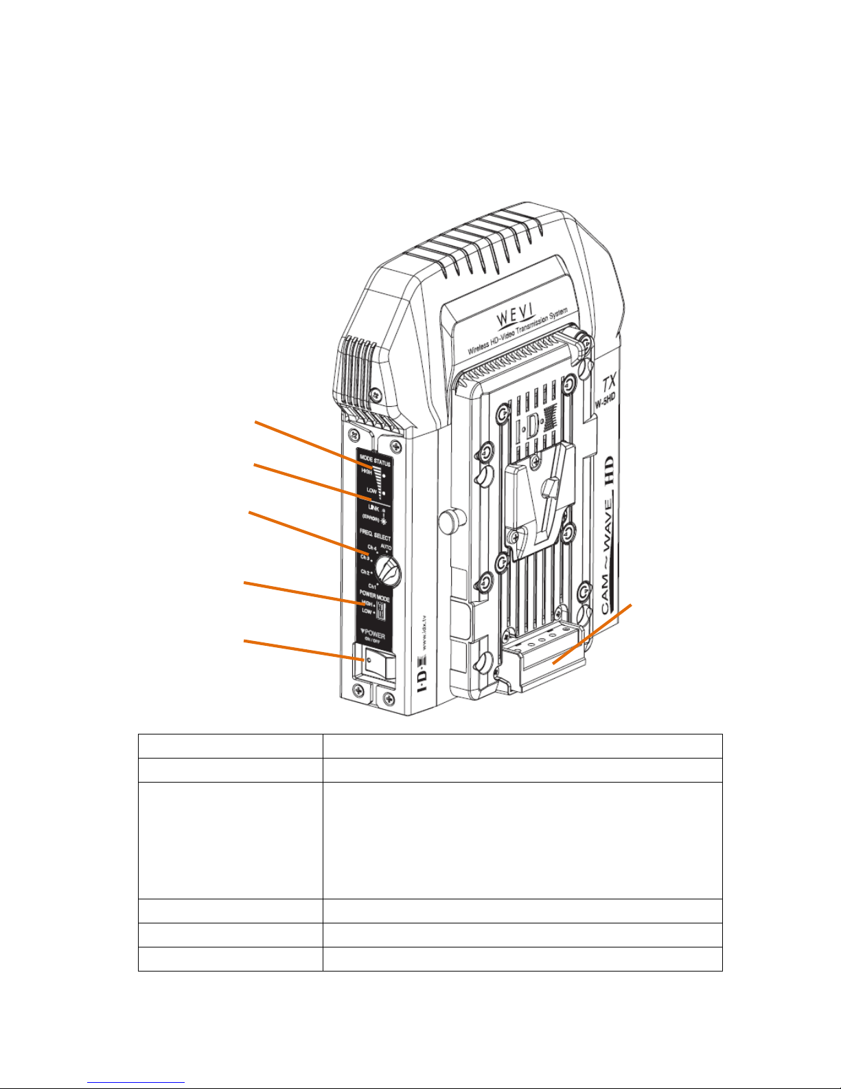
SDI audio with 5GHz band radio frequencies. CW-5HD TX is the transmitter, and
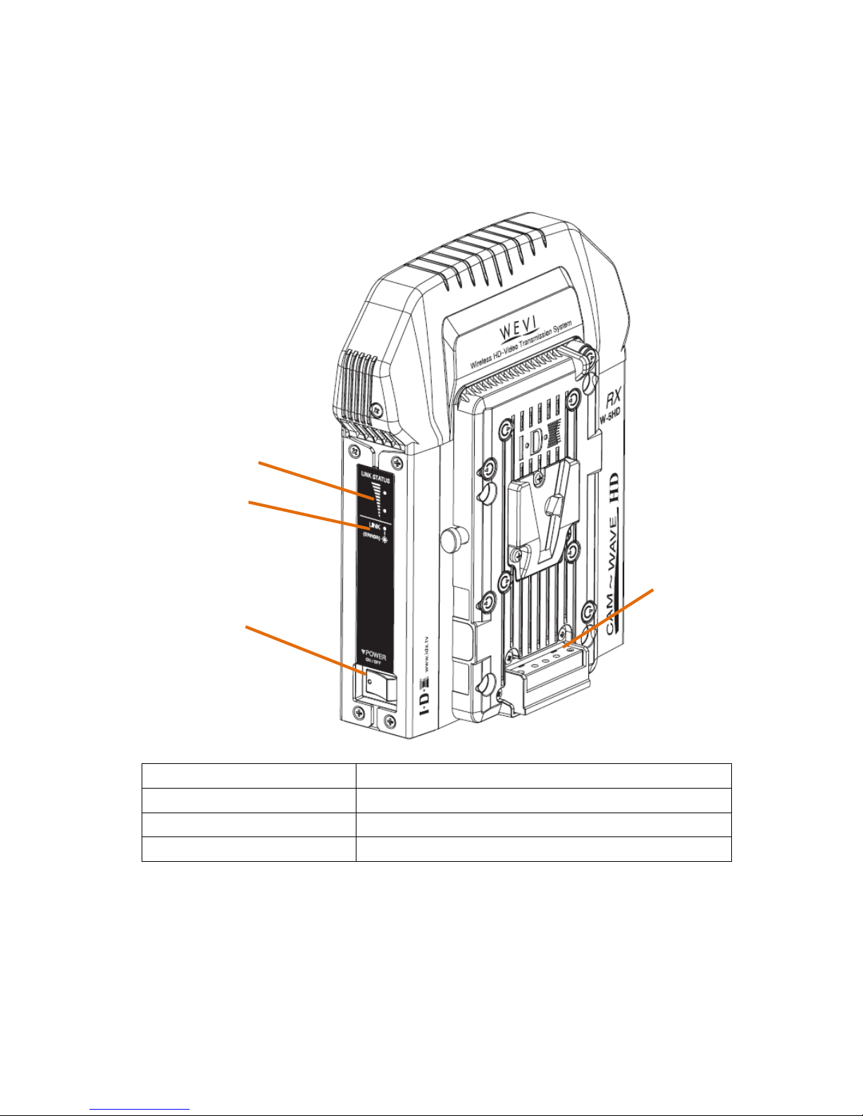
connects to a video source such as a video camera. CW-5HD RX is the receiver,
and connects to a monitor, for example. Video and audio from the video source
can be seen / listened to from a distance without cable connections. Where a
direct line-of-view is offered between CW-5HD TX and RX, the signals can be
transmitted up to 50m (with the transmit output power in HIGH mode).
Other features
zSupports HD-SDI/SD-SDI input and output.
zTransmitting HD video (1080i, 1080p, 720p) and SD video (525i/625i)
zSupporting SDI embedded audio. (Audio CH1 and CH2 only)
zTransmission delay is 1m/sec maximum.
zSignal protection by 256bit AES encryption (in UNICAST mode)
zThe adoption of ‘MIMO’, which multiplexes wireless signals via multiple
antennas in one channel, enables HD-SDI or SD-SDI transmission.
zBoth automatic and manual selection of transmitted frequencies (4ch).
zTwo-level select (HIGH/LOW) of transmit output power.
zPower can be supplied by V-Mount type Lithium Ion battery or by DC input,
via XLR 4P connector.
zBack up power failure function enables immediate and automatic switching
to a connected battery if the external DC connected power is disconnected.
* The transmission distance may vary depending on surroundings, radio wave conditions,
buildings, etc., the transmission distance of approximately 50m is not guaranteed.
* When CW-5HD is placed near a device such a TV, the TV image may be disrupted. Please
increase the distance between TV and CW-5HD when this happens
* In locations with many other devices operating in the 5GHz wireless bandwidth, CW-5HD
operation can be affected, and images may be interrupted.
* Signal reception may be affected by the position, height and angle of placement. If
reception is not stable, please physically adjust placement for the optimised signal.

- 7 -
2. Getting Started
2.1. CW-5HD TX
(Transmitter)
1. POWER MODE LED Indicates selected power output mode
2. LINK STATUS LED Indicates link status (Linked or Searching)
3. FREQ SELECT Selects transmitted frequencies
Manual selection:CH1~CH4
Automatic selection:AUTO
In AUTO position, transmitted frequency is selected
automatically.
4. POWER MODE Selects transmitted output (HIGH/LOW)
5. POWER SW Turns ON/OFF the power of CW-5HD TX.
6. V-Mount Mounts V-Mount type Lithium Ion battery.
②
④
⑥
⑤
③
①

- 8 -
7. SDI IN Connects to the video source’s SDI output connector.
8. SDI OUT Loop-outputs the input SDI signal.
Used to allow for video monitoring on transmit side.
9. UNI/MULTI SW Selects the link mode.
UNI :Unicast mode
MULTI :Multicast mode
10. DC-IN Connect when external power supply is used.
Connector XRL-4P male connector
Input range DC 11~17V
Pin assign No.1:negative(-) No.4:positive(+)
Powers CW-5HD only (does not power camera)
11. V-Plate Mounts CW-5HD TX to the V-Mount of selected source.
⑧
⑨
⑩
⑦
⑪

- 9 -
2.2 CW-5HD RX
(Receiver)
1. LINK LEVEL LED Indicates intensity of received signal.
2. LINK LED Indicates link status (Link on or Searching).
3. POWER SW Turns ON/OFF the power of CW-5HD RX.
4. V-Mount Mounts V-Mount type Lithium Ion battery.
④
③
②
①

- 10 -
5. SDI-1 OUT Connects to the video input connector of monitor, etc.
6. SDI-2 OUT Connects to the video input connector of monitor, etc.
7. UNI/MULTI SW Select link mode.
UNI :Unicast mode
MULTI:Multicast mode
8. DC-IN Connects to external power supply.
Connector : XRL-4P male
Input range : DC 11~17V
Pin assign No.1:negative(-) No.4:positive (+)
Powers CW-5HD only (does not power monitor)
9. V-Plate Mounts CW-5HD RX to V-Mount of selected device
⑨
⑥
⑦
⑧
⑤

- 11 -
3. LED indicators
3.1. LED indicator functions
MODE STATUS LED
Indicates the manually selected transmitted output
power mode (HIGH/ LOW), and the
UNICAST/MULTICAST setting.
POWER MODE HIGH :2 lights on
POWER MODE LOW :1 light on
UNICAST :LED light colour is Green
MULTICAST :LED light colour is Amber
TX
LINK LED
Indicates the link status.
Linked(no video signal):Amber light on
Linked(with video signal):Green light on
Error :Red light blinking
LINK STATUS LED
Indicates the strength of received signal while RX is
linked and the (UNICAST/MULTICAST) setting.
Signal is strong:2 lights on
Signal is weak :1 light on
UNICAST :LED light colour is Green
MULTICAST :LED light colour is Amber
RX
LINK LED
Indicates the link status.
Linked(no video signal): Amber light on
Linked(with video signal):Green light on
Error :Red light blinking

- 12 -
3.2 CW-5HD Link Initialisation (common to TX/RX)
When the power switch of CW-5HD is turned on or the link of the transmitted
signal is lost, the CW-5HD TX and CW-5HD RX will start to search for each
other. The three LED lights will alternate on and off from bottom to top in
sequence, repeating this process until a link is established. This LED
alternating from bottom to top will indicate that the device is searching for a
link.
Searching(TX):Green LED blinks on and off repeatedly
Searching(RX):Green LED blinks on and off repeatedly

- 13 -
4. Selecting frequencies and power output
The CW-5HD TX is equipped with a FREQ SELECT switch and POWER MODE
switch. With the FREQ SELECT switch, the transmitted frequency is set. The
frequency selection is needed only on the TX. The frequency of the RX does
not have to be selected because RX searches for the transmitted frequency
automatically. POWER MODE switch changes the transmitted output to HIGH
or LOW.
4.1. Service frequencies and transmitted output
The service frequencies and the maximum transmitted outputs of CW-5HD
vary according to the designated regions.
The table below shows the service frequencies, corresponding channel
positions and the transmitted outputs for the EU region.
Region Channels
Service
frequencies
(MHz)
Transmitted
power
(HIGH Mode)
Transmitted
power
(LOW Mode)
CH1 5862.5MHz 50mW
CH2 5180MHz
CH3 5200MHz
Europe
CH4 5220MHz
14.5mW 5mW
4.2. Automatic frequency selection
With FREQ SELECT in AUTO position, CW-5HD automatically selects the
channel according to the frequencies assigned to CH1 through CH4.

- 14 -
5. Link modes - UNICAST/MULTICAST
The UNI/MULTI switch is used to select the link mode. The UNI/MULTI select
switches on both the CW-5HD TX and CW-5HD RX must be set in the same
mode.
5.1. UNICAST mode(1:1 communication)
With UNI/MULTI switch in UNI position, CW-5HD links in UNICAST mode. In
UNICAST mode, the link is made only between the same serial numbered pair
of TX and RX (shipped as a pair). The transmitted signals are encoded by
256bit AES and can never be intercepted by other CW-5HD devices.
CW-5HD
TX
CW-5HD
RX
CW-5HD
RX
The pair with the same serial number
CW-5HD RX from different package
The link in UNI position

- 15 -
5.2. MULTICAST mode(1:n communication)
With the UNI/MULTI switch in MULTI position, the CW-5HD links in MULTICAST
mode, in which the CW-5HD TX can send video and audio to more than one
CW-5HD RX. In MULTICAST mode, the transmitted signals are not encoded by
256bit AES encryption.
There is no limit on the number of receiving CW-5HD RX in MULTICAST mode
as long as they are within reach of the transmitted signal and existing
environmental conditions are taken into regard.
Important Notes
zWhen more than one CW-5HD TX are transmitting in MULTICAST mode in
the same location, the CW-5HD RX will link with the first signal that it
receives.
zA single CW-5HD RX can not receive the signal from more than one
CW-5HD TX.
CW-5HD
TX
CW-5HD
RX
CW-5HD
RX
CW-5HD
RX
The link in MULTI position

- 16 -
6. Operation guide
6.1. Set up
The CW-5HD does not include the various accessories that may be used in its
operation. Please separately access the following items as needed for your
specific application prior to use.
zBNC cable for HD-SDI or SDI signal connectivity
zIDX ENDURA system batteries or external power supply
Note: Power supply; Use only an AC adaptor, or batteries, with a DC
output of 11V – 17V. The CW-5HD DC-IN connector is XRL-4P male, pin
assign no.1: negative (-), no.4: positive (+). Do not apply over-voltage
or reverse-polarity voltage since they can cause failure or damage.
6.2. Operating procedures
①Connect CW-5HD TX to the video camera or other transmitting devices
battery source and CW-5HD RX to the receiving monitor’s battery mount.
If either device does not have a V-Mount, use the applicable adapter.
②Connect video device’s SDI output connector to CW-5HD TX SDI input
connector with a BNC cable. Next, connect the CW-5HD RX SDI output
connector to the monitor’s SDI input with BNC cable.
The CW-5HD TX has an SDI output connector, which can be connected to
a monitor for the video source if required. The CW-5HD RX has two
output connectors therefore two monitors, recorders, etc can be
connected simultaneously.
③Connect fully charged ENDURA batteries to CW-5HD TX and CW-5HD RX.
When an external power supply is used, connect to DC-IN connector.
Note: When an ENDURA battery is used, power is supplied to both
CW-5HD and video camera / monitors etc. When external power supply
is used at the DC-IN XLR, power is supplied only to CW-5HD. Video
camera, monitors etc must be powered from another source.
④Set the FREQ SELECT switch, POWER MODE switch, UNI/MULTI switch of
CW-5HD TX in appropriate modes. Set the UNI/MULTI switch of CW-5HD
RX in appropriate mode.
⑤Turn the power ON.

- 17 -
6.3. If reception is unstable
Signal reception may be affected by the position, height and angle of
placement. If reception is not stable, please look for the best condition by
adjusting the location, height, and other environmental variables.
When CW-5HD TX and RX are used close to each other, the received signal
becomes too strong and may disturb the video signal. When they are placed
close to each other (less than 3m as an example), set the POWER MODE
switch of CW-5HD TX to LOW.
6.4. Back-up power failure function
When an external power supply is used, power failure can be avoided by
mounting an IDX ENDURA battery to CW-5HD at the same time. If the
external power supply fails, use can continue via battery power. Depending on
certain conditions, video quality may be momentarily affected.
6.5. Power through function
When the CW-5HD is used with ENDURA batteries, the power supply to the
video camera, monitor, etc. will not stop even when the CW-5HD power switch
is turned off.
If the CW-5HD is not actually required for transmission it can remain on the
video source and turned off. The power from the attached battery will still
power the device even though the CW-5HD is turned off, saving battery
consumption.

- 18 -
7. Notes on Use
(1) The service frequencies and transmit power outputs of CW-5HD vary depending on the
designated regions, because each region has different local regulations or restrictions on
radio waves. The units are
programmed in the factory prior
to shipping. Therefore, a
CW-5HD shipped to one region
can not be used in a different
region.
(2)Outdoor usage of the 5GHz
frequency band, which the CW-5HD uses, is controlled by region. This table shows the
approved frequencies and the corresponding channels of CW-5HD in the EU region.
(3)The maximum transmission distance varies depending on the surroundings, radio wave
conditions, buildings structural composition etc. Although the indoor transmission
distance is indicated as 30m (with CH1, POWER MODE=HIGH), however this is not a
guaranteed operational level.
(4)When the CW-5HD TX and RX are located close to each other, the received signal may be
too strong and may disturb the video. When the CW-5HD TX and RX are used close to
each other (say 3m or less as an example), set the POWER MODE switch of CW-5HD TX
in LOW mode.
(5)CW-5HD can not be equipped with external antennas.
(6)The V-Plate connecting CW-5HD to video cameras, monitors, etc. does not have Digi-View
series II capability for an ENDURA series battery. Therefore, CW-5HD can not support
the battery’s digital communication between an ENDURA battery and video camera.
(7)The SDI output of CW-5HD conforms to SMPTE-292M/SMPTE-259M. However, in some
linked conditions, clock jitter of SDI signals may exceed the regulated values.
(8)CW-5HD uses SDI embedded audio, however only Audio channels 1 and 2 can be
transmitted.
(9)It should be understood that the quality level of video transmitted by wireless signal is not
as good as that by hard-wired cable signals.
Regions Channels
Service
frequencies
Outdoor
usage
CH1 5862.5MHz
Allowed
CH2 5180MHz
CH3 5200MHz
Europe
CH4 5220MHz
Not
allowed

- 19 -
III. Specifications
8. CW-5HD TX
Video / Audio
Video input signal HD-SDI (conforms to SMPTE 292M)
SD-SDI (conforms to SMPTE 259M-C)
Video input connector BNC 1 type
Video output connector BNC 1 type (input signal direct loop through)
Audio input signal SDI Embedded (only CH1,CH2 transmitted)
Video format HD:1080i/59.94, 1080i/50, 1080p/29.97, 1080p/23.98,
720p/59.94, 720p/50
SD:525i/59.94 (NTSC or equivalent), 625i/50 (PAL or equivalent)
Radio
Frequencies 5GHz band
EU version:
CH1: 5862.5MHz, CH2: 5180MHz, CH3: 5200MHz, CH4: 5220MHz
Channels are selected automatically or manually.
Transmitte d
output
HIGH/LOW 2 step manual select
※Outputs of HIGH position vary depending on region and frequencies.
EU version:
HIGH: 17dBm/ approx. 50mW (5862.5MHz)
11.6dBm/ approx.14.5mW (5180MHz-5220MHz)
LOW: 7dBm/approx. 5mW
Transmitting system MIMO / OFDM / JSCC
Antenna Built-in pattern antennas - 2dBi each
Number of antennas Down-link x4 and Up-link x1

- 20 -
Display / Operation
Power switch Power ON/OFF
Input battery power runs through to the output side when the power is OFF.
Frequency
selector
5-position rotary switch
selecting CH1, CH2, CH3, CH4, AUTO
Transmitte d
output switch
Slide switch shifting HIGH/LOW
UNI/MULT switch Slide switch UNI/MULTI
UNI:Unicast mode(1:1 communication / encrypted)
MULTI:Multicast mode(1:n communication / not encrypted)
Status indicator LED in 2 colours: Red, Green ×3
Power
Power supply Battery in:11-17V (using P-V2 IDX V-Mount)
DC in:11-17V [XLR-4 male: No.1 negative (-)/ No.4 positive (+)]
Power output V-Plate (IDX A-NH2E or equivalent)
Applicable
batteries
IDX ENDURA series Li-ion batteries
Battery input power runs through out to the transmitting device.
Automatically switched to battery supply if DC supply fails.
Physical Characteristics
Size Width 158mm (6.22”) Depth 72mm (2.83”)
Height 188mm (7.40”)
Weight 800g approx.
(1.76lbs approx.)
Power
consumption
12W max. (approx.)
Operation
temperature
0~40℃(No Dew)
Approved
standards
CE: ETSI EN 301 893, ETSI EN 302 502, ETSI 301 489-17
FCC: Part 15C, Part 15E
Other manuals for CW-5HD RX
1
This manual suits for next models
1
Table of contents
Other WEVI Receiver manuals
Popular Receiver manuals by other brands

Novatel
Novatel SPAN CPT7 Installation and Operation User Manual

Topfield
Topfield CRC-1400 User reference

Panarex Electronics
Panarex Electronics 4500 user guide

JVC
JVC KD-X362BT quick start guide

Shenzhen Fenvi Technology
Shenzhen Fenvi Technology RC732-DVR user manual

Xpress
Xpress xmc10 installation guide