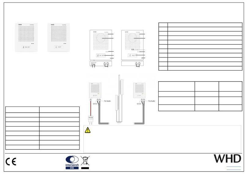
WHD VoiceBridge VBI10 LED User manual

E-Mail: [email protected]
Web: www.whd.de
Dieses WHD-Produkt erfüllt die
CE-Kennzei hnungskriterien. Die
Konformitätserklärung kann beim
Hersteller angefordert werden.
Wir nehmen am INTERSEROH-Verbund teil.
Die Gerätekomponenten k nnen zur Entsorgung der
Kunststoff- und Metallwiederverwertung sowie dem
Recycling von Elektronikteilen zugeführt werden.
WHD - Wilhelm Huber+Söhne GmbH+Co.KG
Bismar kstr. 19
78652 Deißlingen
Support 0 74 20 / 8 89-800
Fax Zentrale 0 74 20 / 8 89-51
Ausgabe des Dokuments
(Te hnis he & optis he
Änderungen vorbehalten)
22.12.2020
- Seite 1 -
Verpackungsinhalt
1 X Voi eBridge / interne Spre hstelle (Personalseite)
1 X Voi eBridge / externe Spre hstelle (Kundenseite)
1 X Netzteil mit Ans hlusskabel (2m)
1 X Verbindungskabel der Spre hstellen (1m)
1 X Bedienungsanleitung
Einführung
Das Voi e Bridge Inter om Set besteht aus einer internen und einer
externen Spre hstelle, zur Erlei hterung von Gesprä hen von Perso-
nen, die dur h eine Wand, eine Glass heibe , ...et . getrennt sind, z.
B. an Kassen, Servi es haltern, … et . Dieses Dokument enthält
Gerätefunktionen und Installationsanleitungen.
Technische Daten
Einsatz als Set VBI10 and VBE10
Stromversorgung 12V DC
3 W
Mikrofon mit AEC + NR
Arbeitstemperatur -20~50
Luftfeu htigkeit 5%~90% RH
Lagerstemperatur -30~60
S hutzklasse IP 33
Material des Rahmens ABS
Abmessungen 110.5 x 86 x 26mm
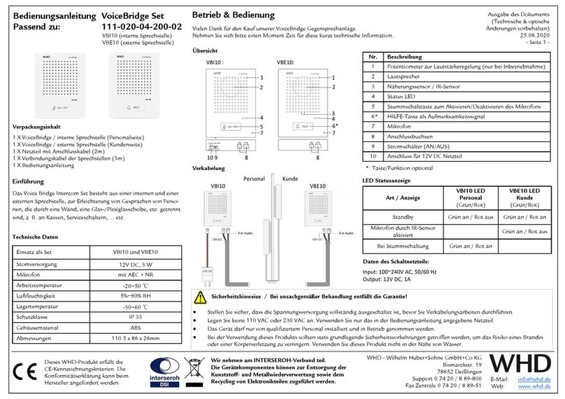
Nr. Beschreibung
1 Potentiometer zur Lautstärkeregelung (nur bei Inbetriebnahme)
2 Lautspre her
3 IR-Sensor / Näherungssensor
4 MEMS Mikrofon (2x)
5 Status LED
6 Stumms halttaste zum Aktivieren/Deaktivieren des Mikrofons
7 Ans hlussbu hsen
8 Stroms halter (AN/AUS)
9 Ans hluss für 12V DC Netzteil
Übersicht
Verkabelung
Personal Kunde
VBI10 VBE10
Sicherheitshinweise
Bei unsachgemäßer Behandlung entfällt die Garantie!
Stellen Sie si her, dass die Spannungsversorgung vollständig ausges haltet ist, bevor Sie Verkabelungsarbeiten dur hführen.
Legen Sie keine 110 VAC oder 230 VAC an. Verwenden Sie nur das in der Bedienungsanleitung angegebene Netzteil.
Das Gerät darf nur von qualifiziertem Personal installiert und in Betrieb genommen werden.
Bei der Verwendung dieses Produkts sollten stets grundlegende Si herheitsvorkehrungen getroffen werden, um das Risiko eines Brandes
oder einer Körperverletzung zu verringern. Verwenden Sie dieses Produkt ni ht in der Nähe von Wasser.
LED Statusanzeige
Operation VBI10 LED
(Grün/Rot)
VBE10 LED
(Grün/Rot)
Standby Grün an / Rot aus Grün an / Rot an
Autom. Aktivierung
dur h IR-Sensor Grün an / Rot aus
Bei Stumms haltung Grün an / Rot an
Näherungssensor
zurü kgesetzt Grün und Rot
blinken
Daten des Schaltnetzteils:
Input: 100~240V AC, 50/60 Hz
Output: 12V DC, 1A
Bedienungsanleitung
VoiceBridge Standard Generation 2
Passend zu: 111-020-04-202-02
VBI10 (interne Spre hstelle)
VBE10 (externe Spre hstelle)
Vielen Dank für den Kauf unserer Voi eBridge Gegenspre hanlage der zweiten Generation.
Nehmen Sie si h bitte einen Moment Zeit für diese kurze te hnis he Information.
Betrieb & Bedienung
1
2
3
5 4
9 8 7 7
VBI10 : VBE10:
2
5
6
1
4

E-Mail: [email protected]
Web: www.whd.de
Dieses WHD-Produkt erfüllt die
CE-Kennzei hnungs-kriterien. Die
Konformitätserklärung kann beim
Hersteller angefordert werden.
Wir nehmen am INTERSEROH-Verbund teil.
Die Gerätekomponenten k nnen zur Entsorgung der
Kunststoff- und Metallwiederverwertung sowie dem
Recycling von Elektronikteilen zugeführt werden.
WHD - Wilhelm Huber+Söhne GmbH+Co.KG
Bismar kstr. 19
78652 Deißlingen
Support 0 74 20 / 8 89-800
Fax Zentrale 0 74 20 / 8 89-51
Anschlüsse und Installation
Schritt 2. Ziehen Sie die S hutzfolie von der Rü kseite der
Spre hstellen ab. Bringen Sie dann die Geräte in die gewün-
s hten Positionen und dü ken Sie diese lei ht auf die Ober-
flä he an.
Schritt 4. Passen Sie die Lautstärke der Geräte bei Bedarf an.
(Hinweis: Die Lautstärke der Geräte wurde vor Verlassen des
Werks auf den besten Wert eingestellt.)
Schritt 3. S hließen Sie die interne Spre hstelle an das S halt-
netzteil an und ste ken dies in die 230V-Ste kdose. Das Inter-
om Kit funktioniert na h einigen Sekunden ordnungsgemäß.
Schritt 5.
Die Entfernung, bei der die Kundenspre hstelle automatis h
aktiviert wird, ist ab Werk auf a. 80 m eingestellt. Dieser
Abstand kann im Berei h von 10 - 100 m eingestellt wer-
den, indem die Reset-Taste 3 Sekunden lang mit einem na-
delartigen Objekt gedrü kt wird, während si h eine Person
im gewüns hten Abstand vor dem Gerät befindet. Wenn die
rote und grüne LED von ON auf blinkend we hseln, wurde
dieser Abstand erfolgrei h übernommen.
Die automatis he Aktivierung der Kundenspre hstelle kann
au h dur h kurzes Drü ken der Reset-Taste mit einem nadel-
artigen Objekt deaktiviert / wieder aktiviert werden. Die rote
LED leu htet während dieses Vorgangs ein/aus.
Schritt 1. Verbinden Sie die interne und externe Spre hstelle mit
dem beiligenden Kabel.
Verpackungsinhalt
Vielen Dank für den Kauf unserer Voi eBridge Gegenspre hanlage der zweiten Generation.
Nehmen Sie si h bitte einen Moment Zeit für diese kurze te hnis he Information.
Betrieb & Bedienung Ausgabe des Dokuments
(Te hnis he & optis he
Änderungen vorbehalten)
22.12.2020
- Seite 2 -
Bedienungsanleitung
VoiceBridge Standard Generation 2
Passend zu: 111-020-04-202-02
VBI10 (interne Spre hstelle)
VBE10 (externe Spre hstelle)

WHD - Wilhelm Huber+Söhne GmbH+Co.KG
Bismar kstr. 19
D-78652 Deißlingen
Support +49 74 20 / 8 89-800
Fax +49 74 20 / 8 89-51 E-Mail: [email protected]
Web: www.whd.de
This produ t supports all CE-
marking riteria. The de laration
of onformity ertifi ate an be
obtained from WHD.
WHD are members of the INTERSEROH association.
We participate in the dual system as well as other
industry-specific solutions. Therefore, plastic, metal
and electronic parts can all be recycled.
Thank you for buying our Voi eBridge Inter om Kit of the 2nd generation.
Please read this manual arefully, espe ially the safety and se urity information.
Version
(Te hni al and opti al
modifi ations reserved)
22.12.2020
- Page 1 -
Scope of delivery
1 X Voi eBridge internal (staff)
1 X Voi eBridge external ( ustomer)
1 X Swit hing power Supply with 2m able
1 X Cable 1m
1 X Manual
Brief Introduction
The Voi eBridge Inter om Kit onsists of one internal unit and one
external unit, mainly used to fa ilitate onversations when the
speakers are separated by a wall, a pie e of glass sheet, … et ., for
example at ashier or servi e ounters.
This do ument ontains devi e features and installation guides.
Manual
VoiceBridge Standard Generation 2
Applicable for 111-020-04-202-02
VBI10 (Voi eBridge internal)
VBE10 (Voi eBridge external)
Technical Parameter
Used in pare VBI10 and VBE10
Power Supply 12V DC
3 W
Mi rophone with AEC + NR
Operation Temp. -20~50
Operation Humidity 5%~90% RH
Storage Temp. -30~60
Prote tion lass IP 33
Frame Material ABS
Dimensions 110.5 x 86 x 26mm
No. Description
1 Potentiometer for volume adjustment ( only by ommission-
ing )
2 Speaker
3 Proximity sensor
4 MEMS mi rophone, x2
5 LED status indi ator
6 Mute key to dea tivate/ a tivate the Mi rophone
7 Conne tion so kets
8 Power swit h
9 12V DC
Product Outline
Installation diagram
Staff Custo er
VBI10 VBE10
Safety Instructions
Improper handling may void warranty!
Make sure turn off all power at the breaker before performing any wiring work.
Do not apply 110VAC or 230VAC. Use only the power supply unit indi ated in do ument requirement.
The devi e must only be installed and put into servi e by qualified ele tri al personnel.
When using this produ t, basi safety pre autions should always be followed to redu e the risk of fire ele tri sho k or personal injury.
Do not use this produ t near water.
LED status indicator
Operation VBI10 LED
(Green/Red)
VBE10 LED
(Green/Red)
Standby Green on/Red off Green on/Red on
Triggered by proximity sensor Green on/Red off
Mute key tou hed Green on/Red on
Proximity sensor reset Green flash/Red
flash
Switching power Supply description
Input: 100~240V AC, 50/60 Hz
Output: 12V DC, 1A
Operation
1
2
3
5 4
9 8 7 7
VBI10 : VBE10:
2
5
6
1
4

WHD - Wilhelm Huber+Söhne GmbH+Co.KG
Bismar kstr. 19
D-78652 Deißlingen
Support +49 74 20 / 8 89-800
Fax +49 74 20 / 8 89-51 E-Mail: [email protected]
Web: www.whd.de
This produ t supports all CE-
marking riteria. The de laration
of onformity ertifi ate an be
obtained from WHD.
WHD are members of the INTERSEROH association.
We participate in the dual system as well as other
industry-specific solutions. Therefore, plastic, metal
and electronic parts can all be recycled.
Version
(Te hni al and opti al
modifi ations reserved)
22.12.2020
- Page 2 -
Installation and setting
Step 2. Tear off the prote tion paper on the ba k of the units,
and then put the devi es to the right position and press them
tightly. Step 4. Adjust the volume of the devi es when ne essary.
Note: the volume of the devi es has been adjusted to the best
level before leaving the fa tory.)
Step 3. Conne t the internal unit to the swit hing power supply
and plug in. The Inter om Kit will be working properly after a
few se onds.
Step 5.
The distan e at whi h the ustomer inter om is automati ally
a tivated is set to approx. 80 m at the fa tory. This distan e
an be set in the range of 10-100 m by pressing the reset but-
ton with a needle like obje t for 3 se onds while a person is at
the desired distan e in front of the devi e. If the red and green
LEDs hange from ON to flashing, this distan e has been su -
essfully adopted.
The proximity sensor an also be dea tivated /re-a tivated by
the pushing the Reset button using a needle like obje t for 1s.
The red LED will turn on/off during this pro ess.
Step 1. Conne t the internal unit and the external unit with the
able supplied.
Contents of package
Thank you for buying our Voi eBridge Inter om Kit of the 2nd generation.
Please read this manual arefully, espe ially the safety and se urity information.
Operation
Manual
VoiceBridge Standard Generation 2
Applicable for 111-020-04-202-02
VBI10 (Voi eBridge internal)
VBE10 (Voi eBridge external)
This manual suits for next models
1
Table of contents
Languages:
Other WHD Intercom System manuals
Popular Intercom System manuals by other brands

LEGRAND
LEGRAND ON-Q IC5002-OB System installation guide

Crestron
Crestron C2N-IVDS24X24 Operation guide

Chamberlain
Chamberlain LiftMaster ELITE EL25 instruction manual

CyberData
CyberData 011414 Installation quick reference

PACH & COMPANY
PACH & COMPANY AeGIS 4000 Installation and programming manual

ELRO
ELRO Pro PV40-P2M2 manual