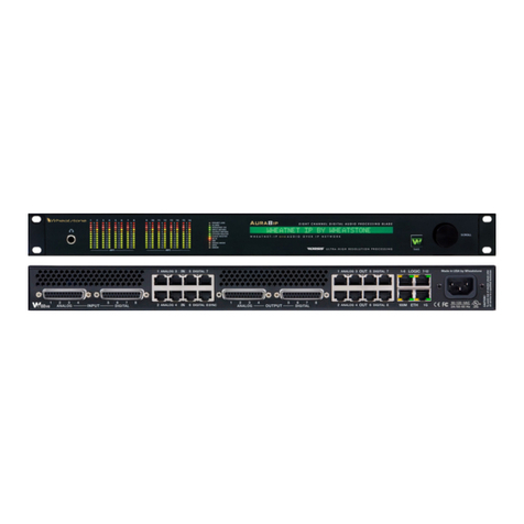
Wheatstone Corporation AM-10HD User manual

Digital auDio Processor
AM - 10 hD
Technical
Manual
Wheatstone Corporation
August 2008

AM-10HD / Aug 2008
Ultra-HigH resolUtion Processing
ORSIS
600 Industrial Drive
New Bern, North Carolina 28562
tel 252-638-7000 / fax 252-637-1285
AM-10HD Digital Audio Processor Technical Manual - 1st Edition
©2008 Wheatstone Corporation

AA
AA
ATTENTIONTTENTION
TTENTIONTTENTION
TTENTION
RR
RR
READEAD
EADEAD
EAD MM
MM
M
EE
EE
E!!
!!
!
AM-10HD / Aug 2008
Attention!
FF
FF
Federal Communications Commission (FCC) Complianceederal Communications Commission (FCC) Compliance
ederal Communications Commission (FCC) Complianceederal Communications Commission (FCC) Compliance
ederal Communications Commission (FCC) Compliance
Notice:Notice:
Notice:Notice:
Notice:
Radio FRadio F
Radio FRadio F
Radio Frequency Noticerequency Notice
requency Noticerequency Notice
requency Notice
NOTE:NOTE:
NOTE:NOTE:
NOTE: This equipment has been tested and found to comply with the
limits for a Class A digital device, pursuant to Part 15 of the FCC rules. These
limits are designed to provide reasonable protection against harmful
interference when the equipment is operated in a commercial environment.
This equipment generates, uses, and can radiate radio frequency energy
and, if not installed and used in accordance with the instruction manual,
may cause harmful interference to radio communications. Operation of this
equipment in a residential area is likely to cause harmful interference in
which case the user will be required to correct the interference at his own
expense.
This is a Class A product. In a domestic environment, thisThis is a Class A product. In a domestic environment, this
This is a Class A product. In a domestic environment, this
product may cause radio interference, in which case, theproduct may cause radio interference, in which case, the
product may cause radio interference, in which case, the
user may be required to take appropriate measures.user may be required to take appropriate measures.
user may be required to take appropriate measures.
This equipment must be installed and wired properly in order to assure
compliance with FCC regulations.
Caution!Caution!
Caution!Caution!
Caution!
Any modifications not expressly approved in writing byAny modifications not expressly approved in writing by
Any modifications not expressly approved in writing by
Wheatstone could void the user's authority to operate this equipment.Wheatstone could void the user's authority to operate this equipment.
Wheatstone could void the user's authority to operate this equipment.

II
II
INTRODUCTIONNTRODUCTION
NTRODUCTIONNTRODUCTION
NTRODUCTION - 1- 1
- 1- 1
- 1
AM-10HD / Aug 2008
MakingAudio Processing History
In 2005 Wheatstone returned to its roots in audio processing with the creation of
Vorsis, a new division of the company. The same year it introduced the model AP-3
DigitalSignalProcessorattheNationalAssociationofBroadcasters(NAB)convention
in Las Vegas.
At the following year’s NAB convention, and with more than 100,000 people in
attendance,VorsisintroducedthemodelHDP3DigitalMultibandSignalProcessorand
the revolutionary model AP-1000 Digital Spectral Processor. The AP-1000 garnered
two coveted industry recognitions: the Radio World “Cool Stuff” award and the BE
Radio “Pick Hit”. With its incredible dual 31-band FM and HD “Fine Grain” limiters
and intuitive graphical user interface the AP-1000 set a completely new performance
standard for high-end broadcast audio processors.
At the 2007 NAB Show Vorsis introduced the FM-5 and AM-5HD processors, as
well as the new and hot-selling M1 Microphone Processor.
Oneyearlateratthe2008NABShow,Vorsisagainsurprisedthebroadcastindustry
with the introduction of five new audio processing products:
AP-2000 and FM-2000: successors to the well-received AP-1000 introduced just
two years earlier, the AP-2000 is targeted for stations needing the power of its dual
31-band FM and HD limiters, while the FM-2000 has all the features of the AP-2000
except the HD signal path.
AM-10HD and FM-10HD: successors to the AM-5HD and extremely popular
FM-5. The AM-10HD and FM-10HD are equipped with dual signal chains for
separately processing the standard analog and HD signals.
VP-8: the first multimode broadcast audio processor with six built-in processing
modes for FM, AM, FM-HD, AM-HD, MP3/AAC>48k, and MP3/AAC<48k. Audio
modesarechanged bysimplyselecting themfromwithin theWindows-basedGUI -no
reboot is required to change from one processing mode to another.
ThesenewVorsisproductsareequippedwithoneormoreofthefollowingexclusive
Vorsis-designed algorithms:
- Vorsis Bass Management System©(VBMS): Finally… clean, deep, low bass
without the distortion that plagues other audio processors. VBMS manages bass by
preventing frequencies that could ‘inter-modulate’ in the main clipper from doing so,
resulting in a dramatically deep low end - and clean midrange - and clean highs –
simultaneously.

page Contents – 1
AM-10HD / Aug 2008
CONTENTS
Chapter 1 – General Information
AM-10HD Technical Manual
Table of Contents
Introduction....................................................................................1-2
Overview.........................................................................................1-4
Rack Mounting...............................................................................1-4
Installation Tips...........................................................................................................1-5
Where to Install the AM-10HD....................................................................................1-6
EAS—United States Emergency Alert System.......................................................1-6
Arbitron People Meter.............................................................................................1-6
Energizing ......................................................................................1-6
I/O Connections.............................................................................1-7
Audio Inputs................................................................................................................1-7
Analog In .................................................................................................................1-7
AES In .....................................................................................................................1-7
Audio Outputs.............................................................................................................1-8
AM Path...................................................................................................................1-8
HD Path...................................................................................................................1-8
Analog Out...............................................................................................................1-8
AES Out...................................................................................................................1-8
Headphones ...............................................................................................................1-8
Network Connection ...................................................................................................1-9
Ethernet RJ-45 ........................................................................................................1-9
Typical Ethernet Cable ............................................................................................1-9
Typical Crossover Cable .........................................................................................1-9
General Purpose Interface (GPI/GPO)......................................................................1-10
GPI .........................................................................................................................1-10
User Presets...........................................................................................................1-11
Example Schematic of General Purpose Inputs.....................................................1-12
GPO........................................................................................................................1-13
Analog XLR Connections Pinouts Drawing ...............................................................1-14
Digital XLR Connections Pinouts Drawing ................................................................1-15
Ethernet RJ-45/GPI DB-9 Pinouts Drawing..............................................................1-16

page Contents – 2
AM-10HD / Aug 2008
CONTENTS
AM-10HD Quick Start Setup Guide ..............................................2-2
Easy Steps to Success...............................................................................................2-3
Install and Connect the AM-10HD..............................................................................2-5
Operating the AM-10HD Locally.................................................................................2-5
Unlocking the Front Panel .....................................................................................2-5
Taking Presets.......................................................................................................2-5
Adjusting the Headphone Level.............................................................................2-6
Operating the AM-10HD Remotely—Installing The GUI Software .............................2-6
Configuring the AM-10HD TCP/IP Address...........................................................2-6
Configuring the AM-10HD .................................................................................2-7
Configuring the GUI...........................................................................................2-8
Additional Notes on AM-10HD GUI Connectivity...................................................2-9
A Known Windows Networking Issue........................................................................2-10
Achieving Your Special On-Air Sound .......................................2-12
First a Few Words About Our Factory Presets..........................................................2-12
What Sound Are You Trying to Achieve?..................................................................2-12
About Bass ................................................................................................................2-13
Is There a Caveat?....................................................................................................2-13
What Is Your Short Term Goal? ................................................................................2-13
How Do I Make It Louder?.........................................................................................2-14
What Is Your Long Term Goal?.................................................................................2-14
Clean and Loud .........................................................................................................2-15
Can I Generate That “Sixties” Compression Sound? ................................................2-16
The AM-10HD Factory Presets ....................................................2-17
Future Presets and Preset Updates ..........................................................................2-17
Architecture of the AM-10HD GUI ................................................3-5
Network Configuration..................................................................3-5
Getting Started...............................................................................3-6
Connecting the AM-10HD and the GUI ........................................3-6
Using a LAN Connection ............................................................................................3-6
Configuring the AM-10HD IP Address....................................................................3-6
Adding Devices.......................................................................................................3-8
Connecting Directly Without a LAN ...........................................................................3-10
PC System Requirements .........................................................................................3-10
Wireless Connection..................................................................................................3-10
The Really Remote Connection!................................................................................3-11
VPN ...........................................................................................................................3-11
The AM-10HD and Internet Security Concerns .........................................................3-11
About DHCP and the AM-10HD ................................................................................3-11
About “Ports” and the AM-10HD................................................................................3-12
Using the AM-10HD GUI...............................................................3-13
Dynamic Displays Region..........................................................................................3-14
Frequency-Domain Graph....................................................................................3-14
AM-10HD Graphical Interface Operation..............................................................3-15
First, a short tutorial..........................................................................................3-16
Chapter 2 – Features and Presets
Chapter 3 – AM-10HD GUI

page Contents – 3
AM-10HD / Aug 2008
CONTENTS
Bargraph Metering................................................................................................3-17
Input Levels / Gain Reduction Meter ................................................................3-18
Output Meter.....................................................................................................3-18
60dB Range......................................................................................................3-18
Display Signal Selection.......................................................................................3-18
Input..................................................................................................................3-18
PreDelay...........................................................................................................3-18
Audio ................................................................................................................3-19
Gain Reduction.................................................................................................3-19
Controls ............................................................................................................3-19
L/R (Left/Right) .................................................................................................3-19
O-Scope ...........................................................................................................3-19
Control Area Region..................................................................................................3-20
Input Menu............................................................................................................3-21
Input Settings....................................................................................................3-21
Input Source .....................................................................................................3-21
Input Signal Presence ......................................................................................3-21
Input Failsafe....................................................................................................3-21
Analog Gain......................................................................................................3-22
AES Gain..........................................................................................................3-22
Balance.............................................................................................................3-22
Phase Rotator...................................................................................................3-22
HPF - High Pass Filter......................................................................................3-23
Why the Sum and Difference High Pass Filter Option?.................................3-23
Parametric Equalizer Menu ..................................................................................3-24
Enable ..............................................................................................................3-25
Automatic Gain Control and Compressor Menu...................................................3-26
Drive ................................................................................................................3-26
Makeup............................................................................................................3-26
AGC/Comp Buttons.........................................................................................3-27
Gated Modes...................................................................................................3-28
Ooze...........................................................................................................3-28
Hold ............................................................................................................3-28
Gate Delay.......................................................................................................3-28
Gate Threshold................................................................................................3-29
Band Coupling.................................................................................................3-29
AGC Backoff....................................................................................................3-30
Crossover Frequencies ...................................................................................3-31
Selecting Crossover Frequencies...............................................................3-31
AGC/Compressor Gain Reduction ..................................................................3-32
HD Output Menu....................................................................................................3-33
Source ..............................................................................................................3-33
Bandwidth.........................................................................................................3-33
HF Protect and HyperMono..............................................................................3-33
HF Protect ..................................................................................................3-34
Ceiling.........................................................................................................3-34
Recovery ....................................................................................................3-34
HyperMono.................................................................................................3-34
Lim/Clip (Limiter/Clipper) Drive ........................................................................3-35
Limiter Enable...................................................................................................3-36
L/R Linked ........................................................................................................3-36
Limiter Thresh...................................................................................................3-36
Attack................................................................................................................3-36

page Contents – 4
AM-10HD / Aug 2008
CONTENTS
Release ............................................................................................................3-36
Delayed Release ..............................................................................................3-37
Clip Style ..........................................................................................................3-37
Phase Reverse.................................................................................................3-37
Left Right Reverse............................................................................................3-37
DeEmphasis .....................................................................................................3-37
Output Level .....................................................................................................3-38
AM Limiters Menu.................................................................................................3-39
10-Band Limiter ................................................................................................3-39
Multiband Enable..............................................................................................3-40
Multiband Drive.................................................................................................3-40
Lim/Clip (Limiter/Clipper) Drive.........................................................................3-40
Multiband Knee.................................................................................................3-40
Multiband Mode................................................................................................3-42
Vorsis Bass Management System (VBMS) ......................................................3-43
VBMS Drive................................................................................................3-43
VBMS Style ................................................................................................3-44
VBMS Output..............................................................................................3-44
VBMS Frequency .......................................................................................3-45
Emphasis Selection..........................................................................................3-45
Look Ahead Limiter...........................................................................................3-46
AM Limiter Controls..........................................................................................3-47
Limiter Enable.............................................................................................3-47
L/R Linked ..................................................................................................3-47
Limiter Thresh.............................................................................................3-47
Attack..........................................................................................................3-47
Release ......................................................................................................3-47
Delayed Release ........................................................................................3-48
Clip Style (Main Clipper).............................................................................3-48
AM Diversity Delay ...........................................................................................3-49
Entering Delay Values................................................................................3-49
10-Band Limiter Dynamics Screens .................................................................3-50
Limiter Threshold Screen ...........................................................................3-50
Clipper Threshold Screen...........................................................................3-51
Attack Time Screen ....................................................................................3-52
Release Time Screen.................................................................................3-53
Final Equalization Screen...........................................................................3-54
AM Transmission Menu........................................................................................3-55
Test Oscillator...................................................................................................3-55
Tilt Test.............................................................................................................3-55
Bandwidth.........................................................................................................3-55
Output Mode.....................................................................................................3-56
Positive Modulation ..........................................................................................3-56
Digital Output....................................................................................................3-57
DeEmphasis ...............................................................................................3-57
PreDelay.....................................................................................................3-57
LF Tilt................................................................................................................3-57
Adjusting the Tilt Corrector.........................................................................3-58
HF Correction ....................................................................................................3-60
System Menu........................................................................................................3-62
System Settings Change With Preset Takes....................................................3-62
Headphone Source...........................................................................................3-63
Headphone Control ..........................................................................................3-64

page Contents – 5
AM-10HD / Aug 2008
CONTENTS
Remote Login ...................................................................................................3-65
Front Panel.......................................................................................................3-65
GUI Access.......................................................................................................3-66
GUI Lock...........................................................................................................3-66
Indicators/Temperature Readout......................................................................3-67
Skin...................................................................................................................3-68
Events...............................................................................................................3-69
Creating a Weekly Rotation Event..............................................................3-70
Creating a Long Term Rotation Event........................................................3-70
Deleting a Scheduled Event .......................................................................3-71
Set Time ...........................................................................................................3-71
Side Bar Region ........................................................................................................3-72
Presets .................................................................................................................3-72
Save .....................................................................................................................3-72
Library...................................................................................................................3-73
Locking Presets................................................................................................3-74
Devices.................................................................................................................3-75
Quick Save (QSave).............................................................................................3-75
Title Bar Region.........................................................................................................3-77
Status ...................................................................................................................3-77
Devices.................................................................................................................3-77
Presets .................................................................................................................3-78
Notes on “Online” and “Offline” working ...............................................................3-78
Accessing Menu Options...........................................................................................3-79
File Menu Items....................................................................................................3-79
Hardware Menu Items ..........................................................................................3-79
AM-10HD Hardware Update.............................................................................3-80
Presets Menu Items..............................................................................................3-81
AM-10HD Signal Flow Diagram ....................................................4-2
Audio Processor (AM-10HD)
Schematic...................................................................................................................4-3
Load Sheet .................................................................................................................4-8
Parameters, Units, and Ranges....................................................A-2
Appendix
Chapter 4 – Schematic and Load Sheet Drawings

page 1 – 1
AM-10HD / Aug 2008
GENERAL INFORMATION
Chapter Contents
General Information
Introduction....................................................................................1-2
Overview.........................................................................................1-4
Rack Mounting...............................................................................1-4
Installation Tips...........................................................................................................1-5
Where to Install the AM-10HD....................................................................................1-6
EAS—United States Emergency Alert System.......................................................1-6
Arbitron People Meter.............................................................................................1-6
Energizing ......................................................................................1-6
I/O Connections.............................................................................1-7
Audio Inputs................................................................................................................1-7
Analog In .................................................................................................................1-7
AES In .....................................................................................................................1-7
Audio Outputs.............................................................................................................1-8
AM Path...................................................................................................................1-8
HD Path...................................................................................................................1-8
Analog Out...............................................................................................................1-8
AES Out...................................................................................................................1-8
Headphones ...............................................................................................................1-8
Network Connection ...................................................................................................1-9
Ethernet RJ-45 ........................................................................................................1-9
Typical Ethernet Cable ............................................................................................1-9
Typical Crossover Cable .........................................................................................1-9
General Purpose Interface (GPI/GPO)......................................................................1-10
GPI .........................................................................................................................1-10
User Presets...........................................................................................................1-11
Example Schematic of General Purpose Inputs.....................................................1-12
GPO........................................................................................................................1-13
Analog XLR Connections Pinouts Drawing ...............................................................1-14
Digital XLR Connections Pinouts Drawing ................................................................1-15
Ethernet RJ-45/GPI DB-9 Pinouts Drawing..............................................................1-16

page 1 – 2
AM-10HD / Aug 2008
GENERAL INFORMATION
General Information
Introduction
The AM-10HD takes a completely new approach to broadcast audio processing through
new and surgically accurate audio processing algorithms created by the our product design
team. The result is far more audio processing power, as well as complete user control over
that power. There are no hidden controls and no secret “back door” hiding things from the
end user. Every control is labeled for exactly what it does, and everything is brought out to
the end user.
The AM-10HD provides the power and the tools required to design the just right sound.
If you can think of the on-air sound you want your station to have, the AM-10HD can create
it for you. This extreme exibility is made possible by our entirely new approach to both
the user interface and clever new DSP audio processing algorithms. The AM-10HD has the
clarity, power, and accuracy of sound not found in any other broadcast audio processor in
its price range.
The AM-10HD is remotely controlled from anywhere via a TCP/IP network connection
and a Windows-based GUI (Graphical User Interface) software application.
AM-10hd Digital Audio Processor
ORSIS
Ultra-HigH resolUtion Processing

page 1 – 3
AM-10HD / Aug 2008
GENERAL INFORMATION
Wheatstone Corporation is a world-leader in broadcast audio equipment design and
manufacturing. Our product line includes audio consoles for the radio and television
broadcast industries, audio control surfaces and digital audio networks, products for
commercial audio applications, and now, our ever-growing and award winning line of
Wheatstone digital audio processors.
Wheatstone began in 1975 as the “Audioarts” company. By 1976, its product line
had already grown to include high quality audio equalizers, electronic crossovers, and
specialized compressor/limiters. In 1977 its rst audio mixing control console was
introduced. Wheatstone returned to its audio processing roots in 2005 when it created
the line of signal processing products and introduced the AP3 Digital Signal Processor
for radio.
Wheatstone’s product line has expanded greatly since the early days, andWheatstone
is now a recognized world leader in radio broadcast consoles, television consoles, and
many types of audio processing equipment.
Wheatstone Corporate Headquarters

page 1 – 4
AM-10HD / Aug 2008
GENERAL INFORMATION
Overview
At the heart of the AM-10HD is a specialized DSP farm containing both oating
and xed-point processors. Advanced signal routing capability allows restructuring the
processing chain as desired, and headphone monitoring can be patched to any processing
section at will. The exibility of the headphone monitoring also allows an audio source
that is attached to the AM-10HD but not even on the air to be monitored!
The most salient feature of the AM-10HD is its specialized “tuned for AM”10-band
nal processing section. This 10-band nal processor morphs its operation as the AM
bandwidth is changed, ensuring that there are always 10 bands of limiting available
regardless of the AM bandwidth selected. Competing designs ‘throw away’ bands as
the bandwidth is decreased leaving fewer and fewer bands to condition the audio for
transmission. Since it makes sense that as bandwidth is reduced more processing ‘help’
is required in order to keep the audio sounding good, the Vorsis method appears superior.
This innovative design allows for far more exible peak control, as well as audio tailor-
ing, than the antiquated limiter algorithms with fewer bands found in other AM audio
processors on the market today.
The 10-band limiter is equipped with fully adjustable thresholds and attack and release
times for each of the bands. Because the AM-10HD’s limiter operates with precision,
time-aligned bandpass lters, regardless of its conguration due to reduced bandwidth
its dynamic operation is nearly invisible to the ear. The resulting on-air sound can be
carefully tailored to create exactly that desired.
Utilizing 10 bands of peak limiting in the AM-10HD and reconguring them on the
y as AM bandwidth is changed allows tuning exibility previously unheard of in any
AM broadcast audio processor.
The AM analog signal path is equipped with an adjustable diversity delay of up to
ten seconds corresponding to the requirements of the North American (iBiquity®) HD
Radio system.
Rack Mounting
The AM-10HD is designed to t into an industry standard 19” equipment rack, and
requires two rack units (3.5 inches) of vertical space.
TheAM-10HD does not have top or bottom cover vent holes. Latent heat is vented out
of the enclosure by natural convection through slots in the top of the rear panel. Cooler
air is drawn into the unit through vertical slots positioned lower in the side panels.
There is a small fan inside the AM-10HD whose purpose is to stir air inside the en-
closure. It does not “remove” heat. In the unlikely even that it should happen, failure of
the fan will not compromise the operation of the AM-10HD.

page 1 – 5
AM-10HD / Aug 2008
GENERAL INFORMATION
The AM-10HD may be mounted between other devices in the equipment rack and,
in accordance with good engineering practice, should not be mounted directly above de-
vices that generate signicant amounts of heat. If such a location is unavoidable then it
is advisable to utilize an extra 1RU blank rack panel between the AM-10HD and devices
immediately above and/or below it.
WARNING! Under no circumstances should the AM-10HD unit be opened! The
unit contains high voltage circuits that are hazardous and potentially harmful. The
unit has no user-serviceable parts inside! If you have a problem the unit must be
returned to Wheatstone Corporation for repair.
Installation Tips:
• Place surge protection circuits as close as possible to the AM-10HD or other device
being protected. This is especially important at AM transmitting plants which often
have less than stellar AC power quality.
• Establish a low impedance common ground in your facility and try to route all grounds
to that point. Transmitter cabinets, phasor cabinets, equipment racks, and, where per-
mitted by electrical codes, the AC power line neutral, should be securely bonded to
the station’s AM ground radial system by low impedance means.
• Choose the best power conditioning / UPS units that you can afford and suitable for
your equipment — focus on the features and options you need. The better UPS prod-
ucts can prevent thousands of dollars in equipment damage — some even come with
an external equipment damage warranty.
• Unbalanced audio connections to the AM-10HD are not recommended in a high-RF
environment such as an AM transmission site. If such interfacing is required it should
be made with shielded two conductor cable such as Belden 8451 or 9451 as if connect-
ing a balanced source. At the unbalanced source’s output connect the + Output to the
HI input wire and connect the source GND wire to the LO wire. Connect the shield
at the AM-10HD end only, noting that in some instances this connection may need to
be made through a 0.01uF capacitor in order to “break” a potential 60Hz ground loop.
• For digital audio connections always use a good quality digital audio cable with a
characteristic impedance of 110 ohms.
The AES/EBU specication, with its broad impedance tolerance, allows for cables with imped-
ances from 88 ohms to 132 ohms - 110 ohms is ideal. Twisted pair cable should be shielded, and in the
case of multi-pair cable, each pair should be individually shielded. Foil shielding is recommended for
permanent installations and foil shield plus overall braid should be used in applications where frequent
exing of the cable will occur. One cable pair is capable of carrying two channels of digital audio.
Generic “audio” cable such as Belden 8451 may be used for interconnecting AES3
digital audio devices but only for distances of less than about 25 feet. The actual cable
length that will work satisfactorily in an installation is primarily determined by the
error correction and jitter tolerance of the AES3 receiver device and the cable used.
The impedance of most “analog” cables ranges from 40 ohms to 70 ohms and represents a large
impedance mismatch from the nominal 110 ohms required in the AES3 standard. Such mismatch will
result in signal reections, causing bit errors at the AES3 receiver. The higher capacitance of generic
analog cables also slows down the rise time of the digital data signals, impairing the ability of the AES3
receiver to accurately detect digital signal transitions. This may result in increased jitter.

page 1 – 6
AM-10HD / Aug 2008
GENERAL INFORMATION
Where to Install the AM-10HD
For best modulation control, in our opinion, the only suitable location for the
AM-10HD is at the transmitter site.
If the AM-10HD must be located elsewhere, the quality of the interconnect-
ing link is critically important. In fact, the requirements for remotely locating
an AM audio processor uniquely parallel the requirements for transmitting an
FM audio processor’s composite baseband signal to a remote transmitter site.
Therefore telco lines, compressed STL’s, and the like should never be used to
carry the processed output of the AM-10HD to a remote transmitter location.
It is better in these instances to carry the unprocessed audio on such links and
install the processor at the transmitter site.
We cannot recommend any other location for the audio processor, including
those associated with various STL’s.
EAS – United States Emergency Alert System
If the EAS generator is placed before theAM-10HD, the levels of the signaling
tones and FSK data may be disturbed by the processing. Therefore it is highly
recommend that the EAS unit be placed after the processing.
If the EAS unit must be installed prior to it, the AM-10HD should be congured
so that when the EAS tones are being sent the AM-10HD is switched to a bypass
or special preset mode. This can be accomplished by using the AM-10HD’s GPI
interface and by assigning a special preset to the EAS function that has internal
processing defeated and audio levels calibrated to provide proper modulation
levels during EAS transmissions.
Arbitron People Meter
The AM-10HD favorably passes the data watermarking scheme used in the
Arbitron rating service People Meter technology regardless of the aggressiveness
of the audio processing performed.
Energizing
Assuming the AM-10HD Digital Audio Processor is correctly rackmount-
ed, you may now energize it. There is no power switch. The AC line input
voltage may be between 90 and 260VAC, 50 or 60Hz. Power consumption is
under 100VA.
Aggressive AC input ltering is utilized at the AC input of the AM-10HD;
however, as mentioned previously, it is always preferable to use external surge
protection and/or an uninterruptible power supply (UPS), especially where AC
power quality is questionable, such as at a remote transmitter site.
Power conditioning, surge suppression, and even power backup devices are
wise investments when using sensitive modern electronic devices that use an
internal computer.
Use of a UPS (uninterruptible power supply) is a good idea and will protect
the AM-10HD from short duration power interruptions which may cause it to
reboot. During boot up, audio is interrupted for approximately 20 seconds.

page 1 – 7
AM-10HD / Aug 2008
GENERAL INFORMATION
I/O Connections
All audio input and output, control, Ethernet, and AC power connections are
made via various connectors mounted on the AM-10HD’s rear panel.
Nine XLR connectors are provided for analog and digital audio input and output
connections.
An RJ-45 connector is provided for Ethernet connection.
Two DB-9 connectors provide 8 GPI inputs (for selecting the rst 8 presets) and
4 GPO outputs.
The pinout drawings on pages 1-14 through 1-16 summarize all wiring connec-
tions.
Audio Inputs
Input audio can be applied to either the analog left/right inputs or to an AES3 digital
input. The AES3 input accepts sample rates between 32 kHz and 96 kHz.
Automatic audio failover from one input to the other is a user selectable option.
Failover from AES3 to analog is instantaneous and based on invalid or missing bits
in the AES3 stream, or after 30 seconds of “silence” (level below -48dBFS). Failover
from analog to AES3 is based on the same silence sense algorithm, responding to audio
below -48dBFS for more than 30 seconds.
Analog In—XLR-F
Pin 1 XLR LT SH – LINE LT IN SH
Pin 2 XLR LT HI – LINE LT IN HI
Pin 3 XLR LT LO – LINE LT IN LO
Pin 1 XLR RT SH – LINE RT IN SH
Pin 2 XLR RT HI – LINE RT IN HI
Pin 3 XLR RT LO – LINE RT IN LO
AES In—XLR-F
Pin 1 XLR SH – AES IN SH
Pin 2 XLR HI – AES IN HI
Pin 3 XLR LO – AES IN LO

page 1 – 8
AM-10HD / Aug 2008
GENERAL INFORMATION
Audio Outputs
AM Path
Output audio for the AM path is available as:
- Analog balanced left/right stereo.
- AES3 digital, either pre or post diversity delay, and/or de-emphasized ac-
cording to any pre-emphasis used.
HD Path
Output audio for the HD path is available as:
- Balanced left/right analog.
- AES3 digital.
Analog Out—XLR-M
Pin 1 XLR AM LT SH – LINE AM LT OUT SH
Pin 2 XLR AM LT HI – LINE AM LT OUT HI
Pin 3 XLR AM LT LO – LINE AM LT OUT LO
Pin 1 XLR AM RT SH – LINE AM RT OUT SH
Pin 2 XLR AM RT HI – LINE AM RT OUT HI
Pin 3 XLR AM RT LO – LINE AM RT OUT LO
Pin 1 XLR HD LT SH – LINE HD LT OUT SH
Pin 2 XLR HD LT HI – LINE HD LT OUT HI
Pin 3 XLR HD LT LO – LINE HD LT OUT LO
Pin 1 XLR HD RT SH – LINE HD RT OUT SH
Pin 2 XLR HD RT HI – LINE HD RT OUT HI
Pin 3 XLR HD RT LO – LINE HD RT OUT LO
AES Out—XLR-M
Pin 1 XLR AM SH – AES AM OUT SH
Pin 2 XLR AM HI – AES AM OUT HI
Pin 3 XLR AM LO – AES AM OUT LO
Pin 1 XLR HD SH – AES HD OUT SH
Pin 2 XLR HD HI – AES HD OUT HI
Pin 3 XLR HD LO – AES HD OUT LO
Headphones
A high-power, overload protected headphone output is
available on the front panel for local monitoring. The head-
phone source can be selected in software to be from one of
six important signal points inside the processing algorithm,
including both analog and AES inputs, even if those inputs
are not selected to feed the audio processing chain.

page 1 – 9
AM-10HD / Aug 2008
GENERAL INFORMATION
Network Connection
The AM-10HD contains its own ve port 100Base-T Ethernet switch with one port
available on the outside of the product reserved for user connections. The Ethernet
switch is equipped with auto-sensing; therefore this port will accept either straight-
through or crossover cables.
Networked systems are normally connected to the AM-10HD via “straight” (pin to
pin) CAT5 cable. For typical CAT5 cable pinouts see below. These connections are for
communicating with the conguration computer via a network. If you are connecting
directly between the computer and the AM-10HD with no network in between, it is
normal to use a crossover cable.
Ethernet—RJ-45
Pin 1 – TXD +
Pin 2 – TXD -
Pin 3 – RXD +
Pin 4 – N/C
Pin 5 – N/C
Pin 6 – RXD -
Pin 7 – N/C
Pin 8 – N/C
Typical Ethernet Cable
Typical Crossover Cable
1
2
3
4
TXD +
TXD -
RXD +
RXD -
PIN
1
2
3
4
PIN
RJ-45
Plug RJ-45
Plug
White/Orange
5
6
7
8
N/
C
N/
C
5
6
7
8
Orange
White/Green
Blue
White/Blue
Green
White/Brown
Brown
N/
C
N/
C
White/Orange
Orange
White/Green
Blue
White/Blue
Green
White/Brown
Brown
1
2
3
4
TXD +
TXD -
RXD +
RXD -
PIN
1
2
3
4
PIN
RJ-45
Plug RJ-45
Plug
White/Orange
5
6
7
8
N/
C
N/
C
5
6
7
8
Orange
White/Green
Blue
White/Blue
Green
White/Brown
Brown
White/Green
Green
White/Orange
Blue
White/Blue
Orange
White/Brown
Brown
N/
C
N/
C
RXD +
RXD -
TXD +
TXD -
N/
C
N/
C
N/
C
N/
C

page 1 – 10
AM-10HD / Aug 2008
GENERAL INFORMATION
General Purpose Interface (GPI/GPO)
The AM-10HD is equipped with eight General Purpose Input (GPI) control
input ports on one female DB-9 connector, and four General Purpose Output
(GPO) tally outputs on a second female DB-9 connector. All GPI and GPO
connections are optically-isolated to prevent interference from high-level RF
elds and external ground loops, and also to prevent dangerous voltages from
being introduced into the AM-10HD.
GPI
The GPI interface provides eight separate General Purpose Inputs, sharing a
common return. The connector is a female DB-9 connector with the following
pin assignments. Note that all pins are isolated fromAM-10HD internal circuitry!
Pin 1 – GPI COM (-)
Pin 6 – GPI 1 IN (+)
Pin 2 – GPI 2 IN (+)
Pin 7 – GPI 3 IN (+)
Pin 3 – GPI 4 IN (+)
Pin 8 – GPI 5 IN (+)
Pin 4 – GPI 6 IN (+)
Pin 9 – GPI 7 IN (+)
Pin 5 – GPI 8 IN (+)
The GPI input circuits are optoisolated by devices having an input/output
isolation of 1,500VAC. These inputs will work very well in high RF environments
and will not cause ground loop issues when connected to external equipment.
Each of the GPI inputs is current limited by a 475 ohm resistance located
inside theAM-10HD’s GPI control circuitry. The LED device inside the optoiso-
lators is rated at a maximum forward current of 50mA and a normal operating
current of 5mA.
Before connecting external circuitry to the GPI inputs you should rst
ascertain whether it will be necessary to utilize additional outboard series
resistance in your application!
The following table will serve as a convenient reference to determine if an
external resistance is required in your application, and if so, what value that
resistance should be. Note that in all applications up to and including 48VDC
a one-half watt resistor power rating is sufcient.

page 1 – 11
AM-10HD / Aug 2008
GENERAL INFORMATION
Applied Voltage to GPI External Resistance
3.3 VDC None
5.0 VDC 330 Ohms
6.0 VDC 470 Ohms
7.5 VDC 820 Ohms
10 VDC 1.3 kOhms
12 VDC 1.8 kOhms
15 VDC 2.4 kOhms
24 VDC 3.9 kOhms
30 VDC 5.1 kOhms
48 VDC 9.1 kOhms
User Presets
The AM-10HD comes with a variety of factory presets and can hold a total of
80 in its onboard memory. You can design and save additional presets within the
AM-10HD’s onboard memory and can store an unlimited number of presets on
the PC that is hosting the remote control GUI software. The factory presets can be
readjusted and then saved to new names in order to create your own unique and
individual sound.
Note: The factory presets are write-protected and changes made to them cannot be written
back to the same memory location. Factory presets whose control settings have been modied
are considered “user” presets and therefore must be saved as a new name and to a new preset
number. Please start with a factory preset that has the on air sound closest to what you need,
and then make any necessary changes to that preset to get to your nal sound.
NOTE: User presets stored in locations 1 through 8 are logically assigned to
the remote GPI function! One example of a type of preset that might be stored
here is a preset that has all processing turned off and has special input/output level
calibrations (Bypass or EAS Preset).
Preset storage is typically as follows:
- Presets 1 - 8 are user presets that can be quickly selected from the GPI con-
nector.
- Factory presets are installed starting at Preset 9, with Preset 9 being a “Bypass”
preset. The factory presets cannot be written over or deleted.
- The number of installed factory presets is subject to change, but is typically
several dozen.
- User presets, other than the GPI selectable presets 1 - 8, are stored above the
highest factory preset. The number of available slots for user presets depends
on how many factory presets were installed.
- User presets may be locked by the user (see Chapter 3). Factory presets, on the
other hand, are locked at the factory. Whereas a user can unlock user-locked
presets, the same user can not unlock factory presets.
Table of contents
Other Wheatstone Corporation Computer Hardware manuals