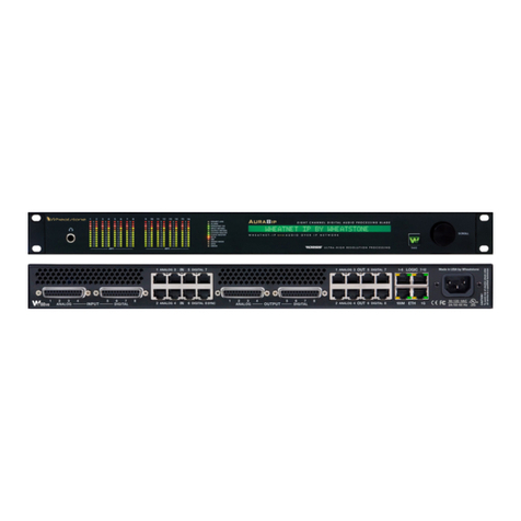
Wheatstone Corporation FM-4 User manual

FM-4
600 Industrial Drive, New Bern, North Carolina, USA 28562
Digital Audio Processor
Technical Manual

FM-4 Digital Audio Processor Technical Manual
©2010 Wheatstone Corporation
FM-4 / October 2010
Ultra-HigH resolUtion Processing
ORSIS
600 Industrial Drive
New Bern, North Carolina 28562
tel 252-638-7000 / fax 252-637-1285

I
Table of Contents
About Wheatstone 1
The History of Wheatstone Audio Processors 2
FM-4 Digital Audio Processor for FM 3
Introduction 3
Feature Highlights 5
Audio I/O 5
Input/Output Latency 5
Local Control 5
Misc. Control I/O 5
Remote Control 5
Software Updates 5
Presets 5
Electrical Requirements 6
Physical 6
Environmental 6
Approvals and Compliance 6
FM-4 Processing Structure 7
Audio Inputs 8
SCA Input 8
Audio Outputs 8
Headphones 8
Network Connection 8
GPI 8
AC Power 8
Rack Mounting 9
Installation Tips 9
Where to Install the FM-4 10
Audio Compression (bit reduction) 10
User Presets 11
Installation and Setup Using the Front Panel 12
Presets 13
Input 13
A Note About Input Levels 13
Network 14
Version 14
Access 14
Introducing Vorsis GUI Lite! 15
Installing the GUI Lite Software 17
Configuring the FM-4 TCP/IP Address 17
Device Configuration – Connecting to the FM-4 18
Setting the Input Audio Levels 21
Setting Output Audio Levels 21
Taking Presets 22

II
Tuning Audio Processing – an Introduction 23
Six Controls! Why Not Just One? 24
How Do the Tweakers Work? 25
What Cause a GUI Lite Control to Stop …. 25
The Six GUI Lite “Tweakers” 27
AGC Depth 27
Compression 27
Density 28
Loudness 28
MF/HF EQ 29
LF/Warm EQ 30
GUI Lite Caveats 31
The Other Two Pages of GUI Lite… 33
I/O Settings Change With Preset Takes 35
Resolving FM-4 Network to GUI Connectivity Issues 37
Unlocking the Front Panel 38
Contacting Wheatstone Technical Support 39
FM-4 GUI Pro – What Is It? 39
Appendix
General Purpose Input – GPI 40

1
About Wheatstone
Wheatstone Corporate Headquarters
New Bern, North Carolina USA
Wheatstone Corporation is the world-leader in extreme-reliability broadcast audio
equipment. Its product lines include audio mixing consoles for the radio and
television broadcast industries, audio control surfaces and digital audio networks,
and our award winning line of Vorsis digital audio processors. Design and
manufacturing of all Wheatstone equipment takes place in our ultra-modern New
Bern, North Carolina, USA headquarters.
Wheatstone’s roots go back over 35 years to the “Audioarts” company when its
product line included very high quality audio equalizers, electronic crossovers,
and specialized compressor/limiters. In 1977 its first audio mixing control console
was introduced to the marketplace.
In 2006 Wheatstone returned to its roots in audio processing when it introduced
its broadcast line of signal processing products for radio

2
The History of Wheatstone Audio Processors
Introduced in 2005, the Vorsis product line evolved from Wheatstone’s return to
its original roots in audio processing. Having designed and integrated analog and
then later, complex digital audio processing, into their radio and television
consoles and control surfaces, Wheatstone was perfectly poised to address the
challenges of combining very high audio quality with competitive on air loudness.
Wheatstone audio processors are built to the same exacting standards as all
Wheatstone products. Research and development, manufacturing, testing, and
quality control for the line of audio processors are all accomplished in
Wheatstone’s large state-of-the-art facility located in New Bern, North Carolina.
Keeping everything under one roof allows Wheatstone to have control over every
facet of product production and ensures that our customers receive products of
the highest possible quality and reliability. Staying true to “Made in the USA,”
Wheatstone does not utilize offshore manufacturing.
A dozen experts with deep experience in Digital Signal Processing, broadcast
audio processing and other engineering disciplines comprise our design team.
Led by audio processing expert and broadcast engineering veteran Jeff Keith,
the team combines their talents to design and build audio processors that
achieve new and higher standards of on air sound quality.
In its short history Wheatstone Processing has already invented many new and
unique audio processing algorithms – algorithms that push audio processor
performance to new and higher levels. Wheatstone was the first to develop a
Vorsis intelligent, ‘program density aware’ AGC (2007 - Sweet Spot Technology,
or SST). We were also the first to employ the science of human psychoacoustics
in the design of a multiband limiter (2005, our acclaimed 31-band final limiter). In
addition, our well-regarded Vorsis Bass Management System (2007, our VBMS)
solves the bass intermodulation problems that plague other brands of audio
processors when pushed for competitive loudness.
Each Wheatstone Processing product comes equipped with its own Windows®
software based intuitive Graphical User Interface for control of the processor.
Carefully tuned factory presets ensure that our audio processors can be placed
into use quickly and easily and in any size market with a minimum of effort.

3
FM-4 Digital Audio Processor for FM
Introduction
Borrowing technologies from our very popular VP-8PLUS audio processor, the
new FM-4 combines a four-band version of our acclaimed DSP-based AGC and
limiter structure with a lab-grade digital stereo generator to create a flexible, low
cost, and yet surprisingly powerful FM audio processor. The FM-4 has the on-air
clarity, power, and accuracy of sound not found in any other FM broadcast audio
processor in its price range.
GUI Lite control software
(shown left) is shipped as a
standard accessory with the
FM-4.
GUI Lite allows non-technical
personnel to quickly achieve
their signature on-air sound
without having to understand
deep and technical audio
processing terms. No audio
processor has ever been so
simple to set up and use.
FM-4 GUI Lite User Interface
The power and intelligence of GUI Lite provides the end user with six simple-to-
use controls that are smart enough to enable morphing of any FM-4 factory
preset to a completely new sound. This flexibility means that if you can think of
the on-air sound you want your station to have, the FM-4’s DSP audio processing
algorithms and its clever user interface can most likely create it for you.
The FM-4 may be remotely controlled from anywhere via a TCP/IP network
connection and the Windows-based GUI (Graphical User Interface) software
application.

4
Note that for those users with experience adjusting audio processing, a
professional version of the FM-4’s GUI (“FM-4 GUI Pro”) is available at no cost
by registering at www.wheatstone-processing.com.

5
Feature Highlights
- Four band time-aligned crossover
- Four band AGC/Compressor with adjustable inter-band coupling.
- Four band limiter
- Exclusive Vorsis Bass Management System (VBMS©)
- FM peak control via oversampled lookahead limiter or oversampled distortion
masked clipper.
- Four band full parametric equalizer.
- Input high pass filter which can be operate in stereo or M/S mode.
- Phase rotator for symmetrical voice waveforms for cleaner processing.
- Precision DSP-based digital FM stereo generator.
- Composite clipper with multiplex filter to protect stereo pilot and SCA region.
Audio I/O
- Analog and AES3 digital audio inputs.
- AES3 digital input accepts sample rates from 32 kHz to 96 kHz.
- AES3 digital output automatically synchronizes to AES3 digital input.
- Separate audio input gains for analog and AES3 digital inputs.
- Low impedance composite MPX output.
- Rear panel SCA/RDS Input
- Front panel headphone output with level control via front panel GUI.
Input/Output Latency
8.9 milliseconds.
Local Control
- Front panel navigation for setup, security and headphone volume control.
Misc. Control I/O
- Eight optoisolated GPI trigger inputs activate presets in storage slots 1-8.
Remote Control
- 10/100 Ethernet-based remote control via rear panel Auto-MDIX RJ-45 jack.
- Windows-based GUI Lite Graphical User Interface*.
Software Updates
- Download to hardware via Windows-based Graphical User Interface.
Presets
- Equipped with more than 25 carefully tuned factory presets.
- 80 preset memory capacity.

6
Electrical Requirements
Voltage: 90–260 VAC, 50-60Hz.
Power consumption: 42 VA (29 watts).
Connector: IEC male, EMI-suppressed. Detachable 3-wire power cord supplied.
Safety Standards: ETL listed to UL standards, CE marked.
Physical
Rack space requirement: One RU (1.75”).
Chassis dimensions: 19” wide x 13.5” deep x 1.75” high.
Unit Weight: 18 lbs (9.98 kg).
Shipping Weight: 26 lbs (16.33 kg)
Environmental
Operating temperature range: 32 degrees F to 122 degrees F (0C to 50C)
Storage temperature range: 20 degrees F to 140 degrees F (-7C to 60C)
Humidity: 0% to 95% RH, non-condensing.
Altitude: 7500 feet AMSL maximum.
Approvals and Compliance
CE and FCC Class A Device.
European Restriction of Hazardous Substances (RoHS) compliant.
* FM-4 GUI Pro is available for download after registering the FM-4 product at
www.wheatstone-processing.com.

7
FM-4 Processing Structure
The FM-4 is equipped with audio inputs for professional analog and digital
sources and the signal processing structure is as follows:
- Analog or AES3 digital audio input;
- High pass filter – L/R or M/S domain;
- Pre-AGC four-band fully parametric equalizer;
- Four-band AGC/compressor;
- Four-band limiter;
- Post-limiter four-band fully parametric equalizer;
- Oversampled, low distortion FM peak controller;
- Lab grade DSP-based digital stereo generator;
- Oversampled composite clipper.
The overall signal flow of the FM-4 is shown in the following block diagram.
FM-4 Block Diagram – Signal Flow
The FM-4 is equipped with a flexible headphone routing scheme to allow
monitoring of audio in various parts of the signal path. It is even possible to
monitor an audio input that is not selected to be on the air. For instance, if the
AES digital input is being used and an analog backup signal is also connected to
the FM-4, the analog input signal can be listened to for confidence monitoring
without having to switch to that input and putting it on the air.

8
Audio Inputs
Input audio can be applied to either the analog left/right inputs or to an AES3
digital input. The AES3 input accepts sample rates between 32 kHz and 96 kHz.
An AES3 digital input applied to the FM-4 determines the FM-4’s AES3 output
sample rate, even if the digital input is not being used. In other words, the FM-4’s
digital input also serves as a sync input for the digital output.
SCA Input
The SCA input accepts audio from an SCA or RDS (Radio Data System)
generator. This input is digitized at 192 kHz after being low pass and high pass
filtered to remove potentially out of band signals.
Audio Outputs
Composite stereo appears on a rear panel BNC female connector and AES3
digital with selectable de-emphasis according to any pre-emphasis in use. The
Composite output is calibrated at the factory to 3.5V P-P, the de-facto standard
level for 100% modulation (75 kHz deviation).
Headphones
A high-power, overload protected headphone output is available on the front
panel for local monitoring. The headphone source can be selected in software to
be from one of several important signal points inside the processing algorithm
including both analog and AES inputs even if those inputs are not selected to
feed the audio processing chain.
Network Connection
The FM-4 hosts a 10/100BaseT Ethernet connector on its rear panel for use with
the Windows-based Graphical User Interface (GUI). The Ethernet interface is
Auto-MDX and therefore the port will accept either straight-through or crossover
cables.
GPI
The rear panel hosts a DB-9 female connector assigned to General Purpose
Input (GPI) functions. The eight inputs are optically isolated to prevent external
ground loops and to keep dangerous voltages from being introduced into the
FM-4. Please see the manual chapter on GPI for the pin assignments for this
connector.
AC Power
An industry standard IEC male connector is provided on the rear panel for
accepting a mating AC power cable. In order to enhance product reliability there
is no power switch.
The AC line input voltage may be between 85 and 265VAC, 50 or 60Hz and
power consumption is under 100VA.

9
Aggressive AC input filtering is utilized at the AC input of the FM-4, however it is
always advisable to use external surge protection and/or an uninterruptible power
supply (UPS), especially where AC power quality can be questionable such as at
a remote transmitter site.
Power conditioning, surge suppression and even power backup devices are wise
investments when using sensitive modern electronic devices such as the FM-4,
which for all practical purposes, is a ‘computer’.
The use of a UPS (uninterruptible power supply) is a good idea and will protect
the FM-4 from short duration power interruptions which can cause the unit to
reboot. During boot up, audio is interrupted for approximately 15 seconds.
Rack Mounting
The FM-4 is designed to fit into an industry-standard 19” equipment rack and
requires one rack unit (1.75 inches) of vertical space.
The FM-4 does not have, nor need, top or bottom cover vent holes. Latent heat is
vented out of the enclosure by natural convection through slots in the top of the
rear panel. Cooler air is drawn into the unit through vertical slots positioned lower
in the side panels.
The FM-4 may be mounted between other devices in the equipment rack, and in
accordance with good engineering practice should not be mounted directly above
devices that generate significant amounts of heat. If such a location is
unavoidable, then it is advisable to utilize an extra 1RU blank rack panel between
the FM-4 and devices immediately above and/or below it.
Installation Tips
Always place surge protection circuits as close as possible to the FM-4 or other
devices being protected.
Establish a low impedance common ground in your facility and try to route all
grounds to that point.
Choose the best power conditioning / UPS units that you can afford and suitable
for your equipment - focus on the features and options you need. High quality
UPS products can prevent thousands of dollars in equipment damage – some
even come with an external equipment damage warranty.
Unbalanced audio connections to the FM-4 should be made with shielded two-
conductor cable such as Belden 8451 or 9451 as if connecting a balanced
source. At the unbalanced source’s output connect the + Output to the HI input
wire and connect the source GND wire to the LO wire. Connect the shield at the
FM-4 end only.

10
For digital audio connections always use a good quality digital audio cable with a
characteristic impedance of 110 ohms.
Generic “audio” cable such as Belden 8451 may be used for interconnecting
AES3 digital audio devices, though for best digital performance it is
recommended that wire length not exceed 10 feet. The actual cable length that
will work well in any installation is determined by the characteristics of the AES3
transmitter in the audio source, the error correction and jitter tolerance of the
AES3 receiver device, and the actual cable used.
Where to install the FM-4
The recommended location for the FM-4 is at the transmitter site if an STL
carrying left and right audio is involved in the signal path. A transmitter site
installation will enable the use of FM-4’s built-in stereo encoder which will always
allow more precise control of modulation peaks.
If the FM-4 must be located at the studio and a composite or digital STL is used
to send the program material to the transmitter there are several issues that need
to be addressed:
Audio Compression (bit reduction)
When using a Digital STL that employs audio bit reduction algorithms (such as
MP3, AAC, etc.) it is highly recommended that the FM-4 be placed at the
transmitter site. This is because the encoding schemes that are used in coded
STLs cannot accurately pass the well-defined peak levels created by the FM-4.
The FM-4 can be placed at the studio end of a compressed STL with at least two
caveats:
1. The high performance composite clipper in the FM-4 cannot be used.
While most modern digital exciters offer a composite clipper function, they
are typically quite crude in their operation compared to what is inside the
FM-4. They are never the optimum choice when sound quality is
important.
2. Data reduced STLs typically do not perform well when processed audio is
applied to their inputs. Dense audio presents fewer ‘opportunities’ to
remove redundant audio information and then correctly mask its removal.
Under those conditions, codec operation may be much more obvious than
it would otherwise, and potentially more so than when the processing is
located after the codec. In the latter case, masked artifacts are
occasionally unmasked by the increased ‘gain’ due to processing; and to
our ears, this sounds better than when dense audio at a codec input
forces it to throw away data that perhaps should not be thrown away.

11
TIP: If using the FM-4 at the studio be certain that the pre-emphasis and clippers
in the stereo generator at the transmitter site are properly set up to match the
settings in the FM-4. This will prevent gross distortion and large modulation
overshoots. Also, in a FM system pre-emphasis should be ‘on’ only in the audio
processor!
User Presets
The FM-4 comes with a variety of factory presets and it can hold a total of 80
presets in its onboard memory. Our factory pre-sets can be readjusted to taste
and then saved under new names on the FM-4, in order to create your own
unique and individual sound.
User presets can also be stored on the host PC (for the GUI) which in most
cases has enough storage for a virtually unlimited number of presets (presets are
typically only a few kilobytes in size).
Note: The factory presets are write-protected and changes to them cannot be
written back to the same memory location. Remember that factory presets
modified by the user are then considered “user” presets and must be saved to a
new preset number.
Note: User presets stored in preset locations 1 through 8 on the FM-4 hardware
are logically assigned to the remote GPI function. Two examples of presets that
might be stored here are:
- A preset that has all processing turned off and has special input/output level
calibrations (for Bypass or EAS Preset).
- A preset that has all processing sections enabled but has the 19kHz stereo pilot
turned off in order to create a “Mono” preset.

12
Installation and Setup Using the Front Panel
The FM-4 is equipped with a front panel menu navigation feature that permits
field installation and configuration without needing a computer. The menu is
navigated by the rotary encoder knob and illuminated “V” button. The items in the
list are arranged in tree form in order to make navigation simple and logical. The
menu is structured so that the Preset selection item is always at the top of the
tree. Logically the navigation list is as follows:
- PRESETS
- INPUT
- OUTPUT
- NETWORK
- VERSION
- ACCESS
An item called “<<MENU” or “EXIT” is always present at the end of a list to
enable backing out of the currently selected item by one level. The entire
navigation tree is shown below.

13
DIGITAL
ANALOG GAIN
INPUT SOURCE
DIGITAL GAIN
ANALOG
Presets
The first menu item in the list is PRESETS which allows scrolling through the list
of factory (and/or user) presets stored on the FM-4 hardware. Once a preset is
decided upon, pressing either the knob or the lighted “V” pushbutton will select
that preset to be active. The active preset will then be displayed on the front
panel alphanumeric display and the preset name will scroll if the name is longer
than eight characters. The FM-4 will respond with “TAKEN” when the preset is
selected, and is loaded and running.
Input
The INPUT menu item allows the appropriate audio input type to be selected
(Analog or Digital) and also allows independent input gain adjustments to be
made for each of the two input types.
A Note About Input Levels
We strongly recommend that peak input audio levels are never set so that they
peak higher than about -12dBFS as shown on either the GUI or the FM-4’s front
panel meters.
This caution is necessary to allow appropriate headroom for the processing
algorithms if they are presented with program material that has been clipped
during the mastering process. Such material can achieve far higher peak levels
after the first stage of signal processing (in any modern audio processor) and
those signals may not have enough headroom to avoid clipping within the
processor if the input level was already too high.
In other words, if you hear mysterious distortion, or what sounds like clipping or a
snapping sound when very loudly mastered material is being played; it’s a good
idea to check the input levels to the FM-4 to ensure they are not spending any
significant time at levels of -12dBFS and above. GUI Lite has a “Ref” indicator on
its input level meter at the -12dBFS calibration mark as a convenient reminder.

14
EDIT
NETWORK
SUBNET MASK
IP ADDRESS
GATEWAY
MAC ADDRESS
HW: x.x.x
SW: x.x.x
DSP: x.x.x
VERSION
OLD:
NEW:
LOCK
CHANGE?
UNLOCK
N
Y
EDIT
ACCESS
Network
After the Output options the Network Configuration is next in the list.
All of the parameters in the Network list can be edited except for the MAC
address. A MAC address is a fixed and permanent hardware identification that is
intended to be specific to and different for each networked device. As is the case
with most network gear, our audio processor’s MAC address cannot be changed.
Version
The version dialog displays the currently loaded versions of operating system,
FPGA image, and DSP code, noting that these are displayed values only and
cannot be changed without actually changing the version(s) of software that the
FM-4 is running; i.e., updating it to a new version using the hardware update
feature in the GUI.
Access
The Access menu item allows the front panel security features of the FM-4 to be
customized. A front panel password may restrict access to the front panel
controls, and can be set or changed when necessary to keep curious fingers out
of the adjustments.
It is not possible to lock the front panel without first setting a password for it.
Likewise, if the front panel has been locked it cannot be accessed without first
entering the valid password.

15
Introducing (
drum roll please
)… Vorsis GUI Lite!
Vorsis GUI Lite for the FM-4 is our standard simplified user interface whose
under-the-hood intelligence distills the FM-4’s hundreds of processing
adjustments down to just six easy to use controls. Finding the perfect sound has
never been quicker. Or easier!
We designed the GUI Lite tool for those who want to change the sound of our
factory presets without having to know and understand the nuances of hundreds
of tweakable parameters.
Adjust Sound Tab
FM-4 GUI Lite – ‘Adjust Sound’
GUI Lite has only three basic pages for hosting the controls that an end user
might need for installing the FM-4 and adjusting its sound.
- The first page of GUI Lite is called “Adjust Sound” and is solely dedicated to
making refinements to our factory presets’ default sound.

16
- The second page of GUI Lite is the “Stereo Generator” page which hosts the
Input and Output Calibrations, the selector for the Headphone monitor source
and the Input Audio Source selector.
- The third and last page of GUI Lite is the “Configuration” page, hosting controls
for selecting the processor mode, configuring the GUI to communicate with the
host Vorsis audio processor and programming the Scheduler.
Note that for user convenience we’ve repeated the appearance of some of the
controls across the three pages noting that the Input, Output and processing-
related metering are always visible on all three pages.
“Adjust Sound” “Stereo Generator”
“Configuration”
Table of contents
Other Wheatstone Corporation Computer Hardware manuals