manuals.online logo
Brands
  1. Home
  2. •
  3. Brands
  4. •
  5. Whelen Engineering Company
  6. •
  7. Floodlight
  8. •
  9. Whelen Engineering Company Continuum 3 User manual

Whelen Engineering Company Continuum 3 User manual

Page 1
©2015 Whelen Engineering Company Inc.
Form No.14903 (063015)
51 Winthrop Road
Chester, Connecticut 06412-0684
Phone: (860) 526-9504
Fax: (860) 526-4078
Internet: www.whelen.com
Sales e-mail: [email protected]
Canadian Sales e-mail: [email protected]
Customer Service e-mail: [email protected]
Automotive: Continuum
Installation Guide:
Continuum™ 3 and Continuum™ 6
LED Floodlights
®
ENGINEERING COMPANY INC.
For warranty information regarding this product, visit www.whelen.com/warranty
Warnings to Installers
Whelen’s off-road equipment must be properly mounted and wired in order to be effective and safe. Read and follow all of Whelen’s written instructions
when installing or using this device. Potentially, this vehicle may be operated under high speed and/or stressful conditions which must be accounted for
when installing any device. Controls should be placed within convenient reach of the operator so that they can operate the system without taking their
eyes off the roadway. Some devices may require high electrical voltages and/or currents. Properly protect and use caution around live electrical
connections. Grounding or shorting of electrical connections can cause high current arcing, which can cause personal injury and/or vehicle damage,
including fire. Many electronic devices can create or be affected by electromagnetic interference. Therefore, after installation of any electronic device it is
necessary to test all electronic equipment simultaneously to insure that they operate free of interference from other components within the vehicle. Never
power equipment from the same circuit or share the same grounding circuit with radio communication equipment. All devices should be mounted in
accordance with the manufacturer’s instructions and securely fastened to vehicle elements of sufficient strength to withstand the forces applied to the
device. Driver and/or passenger air bags (SRS) will affect the way equipment should be mounted. This device should be mounted by permanent
installation and within the zones specified by the vehicle manufacturer, if any. Any device mounted in the deployment area of an air bag will damage or
reduce the effectiveness of the air bag and may damage or dislodge the device. Installer must be sure that this device, its mounting hardware and
electrical supply wiring does not interfere with the air bag or the SRS wiring or sensors. Mounting the unit inside the vehicle by a method other than
permanent installation is not recommended as unit may become dislodged during swerving; sudden braking or collision. Failure to follow instructions can
result in personal injury. Whelen assumes no liability for any loss resulting from the use of this device. PROPER INSTALLATION COMBINED WITH
OPERATOR TRAINING IN THE PROPER USE OF THIS DEVICE IS ESSENTIAL TO INSURE SAFETY.
Warnings to Users
The user should be familiar with all applicable laws and regulations prior to the use of this device.
Safety First
This document provides all the necessary information to allow your Whelen product to be properly and safely installed. Before beginning the installation
and/or operation of your new product, the installation technician and operator must read this manual completely. Important information is contained herein
that could prevent serious injury or damage.
• Proper installation of this product requires the installer to have a good understanding of automotive electronics, systems and procedures.
• Whelen Engineering requires the use of waterproof butt splices and/or connectors if that connector could be exposed to moisture.
• Failure to use specified installation parts and/or hardware will void the product warranty.
• If mounting this product requires drilling holes, the installer MUST be sure that no vehicle components or other vital parts could be damaged
by the drilling process. Check both sides of the mounting surface before drilling begins. Also de-burr the holes and remove any metal shards
or remnants. Install grommets into all wire passage holes.
• If this manual states that this product may be mounted with suction cups, magnets, tape or Velcro®, clean the mounting surface with a 50/50
mix of isopropyl alcohol and water and dry thoroughly.
• Do not install this product or route any wires in the deployment area of your air bag. Equipment mounted or located in the air bag deployment
area will damage or reduce the effectiveness of the air bag, or become a projectile that could cause serious personal injury or death. Refer to
your vehicle owner’s manual for the air bag deployment area. The User/Installer assumes full responsibility to determine proper mounting
location, based on providing ultimate safety to all passengers inside the vehicle.
• For this product to operate at optimum efficiency, a good electrical connection to chassis ground must be made. The recommended
procedure requires the product ground wire to be connected directly to the NEGATIVE (-) battery post (this does not include products that use
cigar power cords).
• If this product uses a remote device for activation or control, make sure that this device is located in an area that allows both the vehicle and
the device to be operated safely in any driving condition.
• Do not attempt to activate or control this device in a hazardous driving situation.
• This product contains high-intensity LEDs. Do not stare directly into these lights. Momentary blindness and/or eye damage could result.
• Use only soap and water to clean the outer lens. Use of other chemicals could result in premature lens cracking (crazing) and discoloration.
Lenses in this condition have significantly reduced effectiveness and should be replaced immediately. Inspect and operate this product
regularly to confirm its proper operation and mounting condition. Do not use a pressure washer to clean this product.
• It is recommended that these instructions be stored in a safe place and referred to when performing maintenance and/or reinstallation of this
product.
• FAILURE TO FOLLOW THESE SAFETY PRECAUTIONS AND INSTRUCTIONS COULD RESULT IN DAMAGE TO THE PRODUCT OR VEHICLE
AND/OR SERIOUS INJURY TO YOU AND YOUR PASSENGERS!
Page 2
Continuum™6 shown.
Continuum™3 lens
replacement and
mounting are
the same.
#6 X 3/8
Plastic-Loc
Screw
Make sure lens asket is seated properlyg
Lens
Retainer
Nylon
Flat Washer
Fig. 3
1/4 x 3/4" long
Socket Head
Cap Screw
(QTY 2)
CAUTION-Hot Surface:
Heat sink fins get hot. Route
all wires away from fins. Keep
vehicle components and
wires away from fins.
1/4" Flat Washer
(QTY 2)
1/4 - 20 Nickel PLD
Brass Elastic
Stop Nut (QTY 2)
Fig. 2
1/4 Flat
Washer (QTY 2)
1/4-20 X 3/4
Carriage
Bolt
1/4 - 20
Nickel PLD Brass
Elastic Stop Nut
Fig. 1
CAUTION: Mounting this product will require drilling. It is
absolutely necessary to make sure that no other vehicle
components could be damaged by this process. Check both
sides of the mounting surface before starting. If damage is
likely, select a different mounting location.
NOTE: The Continuum 6 is shown here. The Continuum 3
mounting and lens replacement is the same.
Mounting:
1. Position the bail bracket
onto the mounting
surface. Mark the spot
where the mounting hole
is to be drilled.
2. Drill the mounting hole
using a drill bit sized for
the 1/4” mounting bolt.
3. Secure the bail bracket to
the mounting surface
using supplied mounting
hardware (Fig. 1).
4. Place the housing into
position on the bail
bracket. Insert the two 1/4” X 3/4” Cap Screws into the two
holes in the rear of the housing (Fig. 2). Using the supplied
hardware secure the housing onto the bail bracket.
5. Adjust light to desired angle and tighten the hardware firmly.
6. Extend the power cable towards your power source. Connect
the RED wire to a +12VDC power source and the BLACK wire
to ground. Install a fuse block and fuse (customer supplied) into
the RED wire near the battery.
Fusing - Continuum 3: 3 AMPS Continuum 6: 3 AMPS
WARNING! All customer supplied wires that connect to the
positive terminal of the battery must be sized to supply at
least 125% of the maximum operating current and FUSED at
the battery to carry that load. DO NOT USE CIRCUIT
BREAKERS WITH THIS PRODUCT!
IMPORTANT: When routing wires, it is important to choose a
path that will keep these wires away from excessive heat and
from any vehicle equipment that could compromise the
integrity of the wires (ex. trunk lids, door jams)
IMPORTANT! Before returning the vehicle to active service,
visually confirm the proper operation of this product, as well
as all vehicle components/equipment.
Lens Replacement:
The Continuum 3 and Continuum 6 lightheads are supplied with
four lenses. A Clear Non-Optic (spot) lens comes standard and
maintains the peak intensity of the light. Also included are a Clear
Optic (Flood) lens, a Smoked Non-Optic lens, and a Smoked
Optic lens. The clear optic (flood) lens spreads the light beam
over a wider area for even more illumination. The smoked
versions of both the optic and non-optic lenses create a unique
and sleek appearance.
1. To replace the lens, remove the screw and washers that secure
the retainer to the light housing (Fig. 3).
2. Remove the retainer and the lens from the housing.
3. Before installing the new lens, make sure the gasket is fully
seated in the housing and is not distorted, twisted or deformed
in any way.
4. Place the new lens onto the housing and remount the retainer.
NOTE: If you are installing an optic lens, the smooth side
goes on the outside (facing away from the light).
CAUTION! DO NOT LOOK DIRECTLY AT THESE LED’S WHILE THEY ARE ON.
MOMENTARY BLINDNESS AND/OR EYE DAMAGE COULD RESULT!
IMPORTANT WARNING!

This manual suits for next models

1

Other Whelen Engineering Company Floodlight manuals

Whelen Engineering Company FLR12 User manual

Whelen Engineering Company

Whelen Engineering Company FLR12 User manual

Whelen Engineering Company Pierce User manual

Whelen Engineering Company

Whelen Engineering Company Pierce User manual

Whelen Engineering Company Pioneer Series User manual

Whelen Engineering Company

Whelen Engineering Company Pioneer Series User manual

Whelen Engineering Company Worklight Series User manual

Whelen Engineering Company

Whelen Engineering Company Worklight Series User manual

Whelen Engineering Company Pioneer Series User manual

Whelen Engineering Company

Whelen Engineering Company Pioneer Series User manual

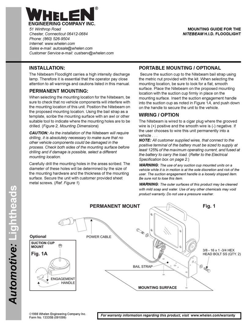
Whelen Engineering Company NITEBEAM H.I.D. Installation instructions manual

Whelen Engineering Company

Whelen Engineering Company NITEBEAM H.I.D. Installation instructions manual

Popular Floodlight manuals by other brands

Robus RHL1030-04 manual

Robus

Robus RHL1030-04 manual

Raytec Spartan Series installation guide

Raytec

Raytec Spartan Series installation guide

Zukt FLZ-100W installation instructions

Zukt

Zukt FLZ-100W installation instructions

LEDLux Lucci ALERT installation instructions

LEDLux

LEDLux Lucci ALERT installation instructions

MARELD PERFORMANCE Series instruction manual

MARELD

MARELD PERFORMANCE Series instruction manual

Elation Design LED 108IP Brochure & specs

Elation

Elation Design LED 108IP Brochure & specs

QED PHOS 75 installation manual

QED

QED PHOS 75 installation manual

Gewiss TITANO manual

Gewiss

Gewiss TITANO manual

Gewiss SMART 4 Series quick start guide

Gewiss

Gewiss SMART 4 Series quick start guide

Wild tech WT-KLD-HID user guide

Wild tech

Wild tech WT-KLD-HID user guide

Emos ZS2711 manual

Emos

Emos ZS2711 manual

ANSMANN WFL800 Original instructions

ANSMANN

ANSMANN WFL800 Original instructions

Cameo CLQS15RGBW user manual

Cameo

Cameo CLQS15RGBW user manual

Harman Martin MAC Aura XIP user manual

Harman

Harman Martin MAC Aura XIP user manual

Selecon HUI CYC user guide

Selecon

Selecon HUI CYC user guide

Philips BVP158 Mounting instructions

Philips

Philips BVP158 Mounting instructions

shada LED's light 30070 Series Installation and operating manual

shada

shada LED's light 30070 Series Installation and operating manual

GP Safeguard RF1 quick guide

GP

GP Safeguard RF1 quick guide

manuals.online logo
manuals.online logoBrands
  • About & Mission
  • Contact us
  • Privacy Policy
  • Terms and Conditions

Copyright 2025 Manuals.Online. All Rights Reserved.