Whelen Engineering Company E-747 User manual

Page 1
©1994 Whelen Engineering Company Inc.
Form No.13585 (011501)
Mass Notification
®
ENGINEERING COMPANY INC.
For warranty information regarding this product, visit www.whelen.com/warranty
OPERATION & INSTALLATION MANUAL
Basic description and operation
of the
E-747 ENCODER
WARNING: This product can expose you to chemicals including Lead which is known to the State of California to cause cancer and birth defects or
other reproductive harm. For more information go to www.P65Warnings.ca.gov.
CANCEL
1SELECT COMMAND 23
SELECT SIREN NUM. SEND
WAIL ATTACK
ALERT
HI-LO
MSG 1
MSG 4
MSG 7
PUBLIC
ADDRESS
WHOOP
MSG 2
MSG 5
MSG 8
AIR
HORN
NOON
TEST
MSG 3
1 SEND2
5
3
6
9
4
7
ALL ON/OFF
8
0
E-747
ENCODER
RESET
MSG 6
SILENT
TEST
R
51 Winthrop Road
Chester, Connecticut 06412-0684
Phone: (860) 526-9504
Internet: www.whelen.com

Page 2
WHELEN ENGINEERING COMPANY INC.
E-747 ENCODER
OPERATION AND INSTRUCTION MANUAL
The purpose of this manual is to provide operation and installation information about the use of a Whelen
Engineering Company Model E-747 Encoder.
Prior to reading this manual or using this product you should be familiar with Whelen Engineering
Company’s family of High Power Voice and Siren Systems.
Document # 04-0113585-00
®
PIONEERS IN SAFETY SIGNALS
ENGINEERING COMPANY INC.
ROUTE 145, WINTHROP RD., CHESTER, CT 06412
TELEPHONE: (800) 63SIREN
TELEPHONE: (860) 526-9504
Sales e-mail: iowsales@whelen.com
FACSIMILE: (860) 526-4078

Page 3
The information contained herein is proprietary to the Whelen Engineering Company.
No part of this manual may be reproduced, recorded or stored in a retrieval system, or
transmitted, in any form without prior written permission of Whelen Engineering
Company.
The software described in this manual is supplied with the understanding that it may
not be copied or otherwise redistributed without prior written permission of Whelen
Engineering Company.
All materials and specifications contained in this document are subject to change
without notice.
Copyright, ©1994 Whelen Engineering Company.
All rights reserved
Printed in the United States of America

Page 4
Table Of Contents
Introduction .................................................................................................................................. page 5
Operation .................................................................................................................................. page 6
General.................................................................................................................... page6
Set-Up...................................................................................................................... page 7
Installation .................................................................................................................................. page 8
Optional DC Use..................................................................................................... page 8
Specifications .................................................................................................................................. page 9
Schematics

Page 5
Introduction
The E-747 Encoder is an easy to use activation unit for Whelen’s family of High Power Voice and Siren
System products. The E-747 output is Whelen’s standard, reliable 10 digit DTMF protocol.
The E-747 is a compact, desktop unit designed for simple 4 wire connection to a base station transmitter.
The E-747 has a sealed membrane keypad for initiating a simple 3 step warning sequence. The warning
activation sequence consists of :
1. Select a command.
2. Select a siren or all sirens.
3. Press the SEND button.
The user may select from 18 different command, or control, functions as listed below:
Wail Digital Voice Message 1 Cancel
Attack Digital Voice Message 2 Silent Test
Alert Digital Voice Message 3
Public Address Digital Voice Message 4
Air Horn Digital Voice Message 5
Hi-Lo Digital Voice Message 6
Whoop Digital Voice Message 7
Noon Test Digital Voice Message 8
CANCEL
1
SELECT COMMAND
23
SELECT SIREN NUM. SEND
WAIL ATTACK
ALERT
HI-LO
MSG 1
MSG 4
MSG 7
PUBLIC
ADDRESS
WHOOP
MSG 2
MSG 5
MSG 8
AIR
HORN
NOON
TEST
MSG 3
1 SEND2
5
3
6
9
4
7
ALL ON/OFF
8
0
E-747
ENCODER
RESET
MSG 6
SILENT
TEST
R
The user may select 1 of 10 individual sirens or “All” sirens in the system.

Page 6
Operation
General
Remember, the E-747 must be ON, as indicated by the “ON/OFF” LED, before anything can happen!
Operation of the E-747 is a simple 3 step procedure as shown on the heading of the unit.
Step 1 is “Select Command” Step 2 is “SELECT SIREN NUM.” Step 3 is “SEND”
Step 1 is shown to the right. Select the command by pressing the appropriate button. The corresponding
LED will light up. If the command was already selected, pressing the button will de-select it and turn the
LED off. Command definitions are as follows:
CANCEL Terminates all siren activity.
WAIL Activates the Wail Tone.
ATTACK Activates the Attack Tone.
ALERT Activates the Alert Tone.
PUBLIC ADDRESS Enables the Public Address mode.
AIR HORN Activates the Air Horn Tone.
HI-LO Activates the Hi-Lo Tone.
WHOOP Activates the Whoop Tone.
NOON TEST Activates the Noon Test function.
MSG 1 Activates Digital Voice Message 1.
MSG 2 Activates Digital Voice Message 2.
MSG 3 Activates Digital Voice Message 3.
MSG 4 Activates Digital Voice Message 4.
MSG 5 Activates Digital Voice Message 5.
MSG 6 Activates Digital Voice Message 6.
MSG 7 Activates Digital Voice Message 7.
MSG 8 Activates Digital Voice Message 8.
SILENT TEST Initiates Silent Test Function.
Step 2 is shown to the right. Select the remote siren by its address number.
The siren number represents the 4th digit of the four digit siren address.
The user may also select all of the sirens by pressing the ALL button. This
places a DTMF # symbol in the 4th digit of the address. The first three
address digits and the area code are set internally. This is explained in a
later section. Siren number definitions are as follows:
0 to 9 4th digit of the siren address.
ALL 4th digit = #, all sirens in system.
ENCODER RESET Resets the encoder, clears entries.
Remember, only one specific siren, or all sirens, may be addressed at a
time.
CANCEL
1SELECT COMMAND
WAIL ATTACK
ALERT
HI-LO
MSG 1
MSG 4
MSG 7
PUBLIC
ADDRESS
WHOOP
MSG 2
MSG 5
MSG 8
AIR
HORN
NOON
TEST
MSG 3
MSG 6
SILENT
TEST
2SELECT SIREN NUM.
12
5
3
6
9
4
7
ALL
8
0
ENCODER
RESET

Page 7
3SEND
SEND
Step 3 consists of deciding whether or not to send the selected command. Pressing
the SEND button will send the command. There is NO second chance!! After sending
the command, the LED of the issued command will flash. The siren number remains
on steady. The SEND LED turns off.
Remember, if there is no LED response, the button has not been properly pressed.
For a Public Address function, be sure to send the PUBLIC ADDRESS command before keying up the
microphone and talking.
Note: The microphone is not included. Refer to Model WPSNCMIC, part # 01-0245719-00.
EXAMPLE: Activate the Alert Tone at remote siren number 3.
Make sure the E-747 is on.
Press the ALERT button, press the 3 button, press the SEND button.
Set-Up
Remove power before opening the E-747.
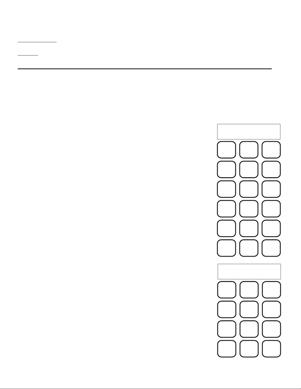
The system area code and the first three digits of the address are typically
factory set. However, if the need arises to change these switches it may be done
by the user. The settings are made with rotory switches, located inside of the
E-747 housing. To access the switches, remove the two Phillips head screws
on the bottom of the unit. Gently remove the top of the housing, without
removing any cables. The switches are located on the base mounted circuit
board, as shown. Notice that each switch is labled. Starting at the bottom, are
AC-1, AC-2 and AC-3 which identify the first, second and third digits of the
three digit Area Code. As shown, the Area Code is 080. The top three
switches are AD-1, AD-2 and AD-3 which identify the first, second and third
digits of the four digit Address. As shown, the Address is 400X, where X is
selected from the keypad during Step 2.
Note that the switches go from 0 to F. The Area Code digits will only use 0 to
9. However, the Address may be 0 to 9 or the letter C. The letter C represents
a # symbol or wildcard.
Caution should be used in changing the Area Code. This value is typically
set at the factory to insure a unique value. Any changes to this value should
be discussed with the factory, to avoid future confusion.
0
0
0
0
0
0
1
1
1
1
1
1
2
2
2
2
2
2
3
3
3
3
3
3
4
4
4
4
4
4
5
5
5
5
5
5
8
8
8
8
8
8
C
C
C
C
C
C
D
D
D
D
D
D
E
E
E
E
E
E
F
F
F
F
F
F
B
B
B
B
B
B
A
A
A
A
A
A
9
9
9
9
9
9
7
7
7
7
7
7
6
6
6
6
6
6
AD-3
AD-2
AD-1
AC-3
AC-2
AC-1

Page 8
Installation
This step-by-step procedure for installing the E-747 is intended for use by a qualified radio technician.
1. Inspect the E-747 for any physical damage.
2. Locate the 4 conductor cable on the back of the E-747. This cable connects to the base
transmitter, as follows:
Green - Audio Return
White - Audio
Red - Push To Talk
Black - Push To Talk
3. Set the transmitter warm-up time. Locate the rotary switch in the back of the E-747. Select the
warm-up time by setting the switch to the appropriate position, as shown in the table.
Warm-up Time Switch Position
100 ms 0
500 ms 1
1 second 2
2 seconds 3
4. Plug the wall mount transformer into a 115 volt AC source. Press the ON/OFF button to turn the
E-747 on. The ON/OFF LED should be lit.
5. Locate the recessed LEVEL and MIC VOL adjustments on the E-747. A small flat bladed
screwdriver is needed for the adjustment.
6. Set the DTMF Tone level. With the E-747 on, press the CANCEL button (the LED should be on),
select siren number 1, and press SEND. While the tone is transmitting, adjust the LEVEL
potentiometer for 2.5 KHz deviation. Repeat this step as needed to adjust the level.
7. Set the microphone level. Plug the microphone into the MIC jack. Key up the microphone and
adjust the MIC VOL potentiometer for 4 KHz deviation, while speaking into the microphone.
Note: The microphone is not included. Refer to Model WPSNCMIC, part # 01-0245719-00.
Optional Automotive (or 12 VDC) Installation
Follow the procedure, as described above, with the following exception at Step 4.
Instead of plugging into AC, cut the cable from the wall mount transformer, or supply a cable with the
appropriate plug. The white stripped wire is the positive DC lead. Connect the positive DC lead to a
nominal 12 VDC source through a 1 Amp fuse. Connect the ground wire to the 12 VDC Ground. The VDC
range may be 11 to 15 VDC.

Page 9
SPECIFICATIONS
GENERAL -
Input Power: 12 volt DC nominal, 60 mA typ., 150 mA max.
UL listed wall mounted transformer.
Physical: Desktop design, almond color.
2.1” H x 6.9” W x 6.7” D.
1.1 pounds.
Environmental: Operating temperature, -20°C to +60°C.
Humidity, 0-90%, non-condensing.
Output: 4 wire cable for audio and PTT.
Audio: 2 wire, 600transformer balanced, adjustable.
Control: Normally open relay for Push To Talk.
Contact rating, 1/2 A @ 120 VAC, 1 A @ 12 VDC.
Signaling: DTMF format, Whelen 10 digit protocol.
REAR PANEL CONTROLS -
Transmit Warm-up: 100 ms, 500 ms, 1 second, 2 second
Selector switch.
DTMF Tone Level: Variable.
Microphone Volume: Variable.
Microphone Jack: Ground, Signal, PTT.

Page 10
C
COPYRIGHT, WHELEN ENGINEERING COMPANY
PIONEERS IN SAFETY SIGNALS
TELEPHONE (203)526-9504
CHESTER, CT06412-0684
ROUTE 145
ENGINEERING COMPANY
WHELEN ENGINEERING COMPANY ANY REPRODUCTION, DISCLO-
SURE OR USE OF THIS DRAWING IS EXPRESSLY PROHIBITEDEXCEPT
AS THE WHELEN ENGINEERING COMPANY MAY OTHERWISE AGREE
IN WRITING.
THIS DRAWING CONTAINS INFORMATION PROPRIETARY TO THE
TOLERANCE UNLESS OTHERWISE SPECIFIED-ANGLES ±1/2
CODEIDENT.
MATERIAL
FINISH
DR.
CH.
ENG.
APP.
SCALE
DATE
DRAWING NO.
SHEET OF
REV.
R
C20
50V
.47UF
50V
.47UF
C20
.1UF
+
100UF
+
10UF
LM341T
.1UF
+5V
50V
25V
13
47K
VSS
VDD
1
14,20,21
VCC
4039
19
17
SCLK
MISO
PD7
PD6
PB7
PB6
PB5
PB4
RST
31
30
29
28
12
11
1
5
4,13
GS,NC
VSS
10
D0
D1
D2
D3
9
11
12
+5V
50V
VDD
TP5088
1K
14
TONE OUT
EXTAL
XTAL
OSCOOSCI
67
3.579 MHZ
10M
27PF
.1uF
+12V
25V
50V
200V
Y1
C16
R19
R2
C2
R18
IC4
IC6
VR1
C12 C11 C10 C9
Y2
4.00 MHZ
200V
27PF
C15
PCW
PCW
1994
3
4
5
6
11
12
13
14
RN1
47K
3
4
5
6
11
12
13
14
RN2
47K
47K
RN3
14
13
12
11
6
5
4
3
9
10
7
2
1
9
10
7
2
1
1
2
7
10
9
SW3
SW5
SW7
SW6
SW4
SW2
SS
MOSI
18
1A
A
IC3
74HC165
B
C
D
E
F
G
H
A
IC2
74HC165
B
C
D
E
F
G
H
A
IC1
74HC165
B
C
D
E
F
G
H
GND
816
VCC
+5V
CE
15
+5V
16
CE
15
VCC GND
+5V
16
CE
15
VCC GND
F1
.1UF/50V
C4
C17
.1UF/50V
C18
.1UF/50V
SI
SCLK
LOAD
SO
SO
SI
SCLK
LOAD
SO
SO
SI
SCLK
LOAD
SO
SO
2
24
PA3 TONE EN
STE
3
8
8
16
PD1
PD0
15
D2
1N5061
R12
47K
VCC
GND
3,6
SIG IN
2
VCC
1
O15
8
O2
TDA7052A
+12
BC337
Q1
K1
D4
R9
47K
RZ
12C
42TM023
K1
R8
10K
5K
R1
B+
1K
R13
1K
R14
C14
35V
2.2UF
+
B+
C1
.47UF
74HC4066
VCC
VCC
1N4005
D3
R4
5K
R7
4.7K
C8
74HC4066
.47UF
C3
B+
B+
50V
50V
50V
.47UF
C13
K1
5
34
13
21
7
PC5
PC6
6
PC4
5
PC3
4
PC2
3
PC1
2
PC0
32
PB3
33
PB2
34
PB1
35
PB0
PC7
9
8
68HC711D3
RN4
4.7K
T1
IRQ
R5
4.7K
R6
2.7K
.47UF
50V
R17
47K
R15
47K
R16
47K
4.7K
R11
PA5
R20
10K
VCC
XIRQ
10
27
PA0
23 22
PA7
RN2
47K47K
RN1
VCC
25
PA2
26
PA1
0
9
8
7
6
5
4
3
2
1
2
1
3
4
C7
.022UF
R10
100K
VOL
4
10uF
C5
13
12
10
9
8
2
3
4
5
6
11
7
1
14
2
6
4
5
3
VCC
1
R3
4.7
1/2W
.47UF
50V
C6
J5
SW1
J2
J4
IC7
IC7
14
C19
.1UF
50V
25V50V
6,7,8,9
10,11,12
VCC
+
IC5
J3
P6KE18A
D1
J1
ITEMQTY. DESCRIPTIONPART NUMBER
--
02-0167577-00 E747ENCODER CPU PCBDSCHEMATIC
E747ENCODER
CPU PCBD
67577 C
SCHEMATIC
NONE
8-11-94
13
1N4005
R21 680
R22 680
R23 680
R24680
LTG
TMF

Page 11
LTG
ITEMQTY. DESCRIPTIONPART NUMBER
1994
LTG
--
02-0167579-00 E747ENCODER LEDPCBDSCHEMATIC
E747ENCODER
LEDPCBDSCHEMATIC
2=1
8-9-94
67579 B
13
+5V
12
11
10
9
16
15
14
13
6
2
7
1
5
O1
IC1
O2
O3
O4
O5
O6
O7
O8
48
VCC GND
.1UF/50V
C2
SCLK
SI
LATCH
OE
SO
+5V
R17
240
240
R15
R16
240
240
R14
R8
240
240
R9
R1
240
240
R10
D22D15D14D16D9D8D10D1 D26D12D19D17D18D25D23D24
R12
240
240
R21
R18
240
240
R20
R28
240
240
R19
R26
240
240
R27
+5V
SI
OE
LATCH
SO
SCLK
C5
.1UF/50V
GNDVCC
84
O8
O7
O6
O5
O4
O3
O2
IC4
O1
2
1
7
5
6
13
14
15
16
9
10
11
12
3
LGND
3
LGND
LGND
3
LGND
3
12
11
10
9
16
15
14
13
6
5
7
1
2
O1
IC2 O2
O3
O4
O5
O6
O7
O8
4
8
VCCGND
.1UF/50V
C3
SCLK
SO
LATCH
OE
SI
+5V
R11
240
240
R13
R2
240
240
R3
R4
240
240
R5
R6
240
240
R7
D11 D13 D2 D3 D4D5 D7 D6
D20 D21 D29 D28 D27 D30 D32 D31
R23
240
240
R22
R25
240
240
R24
R30
240
240
R29
R31
240
240
R32
+5V
SO
OE
LATCH
SI
SCLK
C4
.1UF/50V
GNDVCC
8
4
O8
O7
O6
O5
O4
O3
O2
UCN5821A
IC3
O1
5
1
7
2
6
13
14
15
16
9
10
11
12
2
1
3
4
5
6
C1
100uF/25V
P1
UCN5821A
UCN5821A
UCN5821A
AB
R
REV.
OFSHEET
DRAWING NO.
DATE
SCALE
APP.
ENG.
CH.
DR.
FINISH
MATERIAL
CODEIDENT.
ANGLES ±1/2
TOLERANCE UNLESS OTHERWISE SPECIFIED-
THIS DRAWING CONTAINS INFORMATION PROPRIETARY TO THE
IN WRITING.
AS THE WHELEN ENGINEERING COMPANY MAY OTHERWISE AGREE
SURE OR USE OF THIS DRAWING IS EXPRESSLY PROHIBITEDEXCEPT
WHELEN ENGINEERING COMPANY ANY REPRODUCTION, DISCLO-
ENGINEERING COMPANY
ROUTE 145
CHESTER, CT06412-0684
TELEPHONE (203)526-9504
PIONEERS IN SAFETY SIGNALS
COPYRIGHT, WHELEN ENGINEERING COMPANY
C
Table of contents
Other Whelen Engineering Company Media Converter manuals
Popular Media Converter manuals by other brands

Baumer
Baumer POG 11 Mounting and operating instructions

AMP
AMP MPEG4000-D4 Hardware reference manual

Moxa Technologies
Moxa Technologies NPort 5100A Series Quick installation guide

DENAFRIPS
DENAFRIPS Ares manual

Littfinski Daten Technik
Littfinski Daten Technik TurnTable-Decoder operation instruction

Wolverine
Wolverine MovieMaker Pro manual