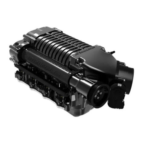
Whipple LT1 User manual

Installation Manual: GM LT1_A1R13E
Last Updated: February 12th, 2019
Page 1 of 36
www.whipplesuperchargers.com
SUPERCHARGER INSTALLATION MANUAL
2014-2018 GM 5.3/6.2 LT1 TRUCK
2014-2019 GM 5.3/6.2L LT1 SUV
WHIPPLE SUPERCHARGERS
3292 NORTH WEBER AVE
FRESNO, CA 93722
TEL 559.442.1261
FAX 559.442.4153
www.whipplesuperchargers.com
A color PDF of this manual is available, email
tech@whipplesuperchargers.com for a copy
PREMIUM FUEL ONLY (91 OCTANE OR BETTER ALWAYS) RON+MON/2
CALIFORNIA AIR RESCOURCE BOARD EXECUTIVE ORDER #D231-48

Installation Manual: GM LT1_A1R13E
Last Updated: February 12th, 2019
Page 2 of 36
www.whipplesuperchargers.com
INTRODUCTION
Before beginning installation, we encourage you to read this manual thoroughly before you begin any portion of the installation:
1. A quick parts check to make certain your kit is complete (see shipper parts list in packing paperwork). If you discover
shipping damage or shortage, please call our office immediately.
2. Review our limited warranty with care.
3. Always wear eye protection during installation.
4. Avoid spills, if one occurs, clean up and dispose of towels properly.
5. Never work on a hot engine.
6. Obey all traffic laws when testing the vehicle.
COMPETITION BASED PRODUCT MAY BE USED SOLELY ON VEHICLES USED IN SANCTIONED COMPETITION WHICH
MAY NEVER BE USED UPON A PUBLIC ROAD OR HIGHWAY, UNLESS PERMITTED BY SPECIFIC REGULATORY EXEMPTION
(VISIT THE “EMISSIONS” PAGE AT HTTP://WWW.SEMASAN.COM/EMISSIONS FOR STATE BY STATE DETAILS.
COMPETITION BASED PRODUCT IS LEGAL IN CALIFORNIA ONLY FOR RACING VEHICLES WHICH MAY NEVER BE USED,
OR REGISTERED OR LICENSED FOR USE, UPON A HIGHWAY.
IT IS THE RESPONSIBILITY OF THE INSTALLER AND/OR USER OF THIS PRODUCT TO ENSURE THAT IT IS USED IN
COMPLIANCE WITH ALL APPLICABLE LAWS AND REGULATIONS.
RECOMMENDED TOOLS AND SUPPLIES
The following items are not included in this supercharger kit and it is strongly recommended that they're used for ease of
installation or maximum performance:
Extra Components
2 gallons distilled water, 2 gallons GM approved coolant, 4”, 8” and 12” zip-ties, clean shop towels.
Tools
Torque wrench (1/4”, 3/8”, ½”) Safety glasses, standard and metric wrench set, 1 ½” hole saw, ¼”, 3/8”, ½” assorted
metric socket set, 3/8” assorted metric allen socket set, 3/8” assorted torx socket set, 8mm nut driver, screw driver set,
pinch clamp tool, wire cutters and drain pan (for coolant).
Tie Straps
These will be useful for securing the wiring harness away from the installation area as directed in the instruction manual.
They are inexpensive and will be very handy during installation.
Sealants
Blue Loctite™#242 or equivalent, Red Loctite™ #271 or equivalent. All bolts that need Loctite™ are marked with:
Loctite™ (#242 blue) threads, Loctite™ (#271 red) threads. Thread sealant such as pipe Teflon must be used
on all pipe threads.
Chemicals and lubricants
You will need some cleaner/degreaser such as carb cleaner. Motor oil and clear automotive-type grease (example
Lubriplate #105) will be useful as a lubricant and should be readily available during installation.
You’ll be required to fill your intercooler system with approx. 1 gallon of distilled water and GM approved engine coolant.
This is not supplied in the system, you can find the coolant at any local auto parts store. NEVER USE TAP WATER, as it
can corrode and create poor performance.

Installation Manual: GM LT1_A1R13E
Last Updated: February 12th, 2019
Page 3 of 36
www.whipplesuperchargers.com
PRE-INSTALLATION CHECKLIST
Before installing your Whipple Supercharger Kit, complete the following checklist.
1. Verify Condition of Vehicle: Before the supercharger kit is installed, ensure the engine runs smoothly and that the
factory malfunction indicator light (MIL) is off. Only install the supercharger kit if the engine runs smoothly
and
the
MIL is off.
2. !! CAUTION !!
This product is intended for use only on STOCK, UNMODIFIED, WELL-MAINTAINED engines. Installation
on a worn-out or modified engine is not recommended without factory computer and fuel system
modifications. Custom engine configurations could require custom tuning and other supporting
modifications.
3. !! CAUTION !!
Use only 91 octane fuel or higher. If fuel of less than 91-octane is present in the vehicle fuel tank, the
tank must be completely drained and refilled with 91 or higher octane to 1/8th of a tank.
4. Verify Fuel System: Supercharger systems should only be installed on vehicles that have new or clean fuel filters.
5. Assess Cleanliness of Installation Area: Make sure your work area and the under-hood area are free from debris. This
supercharger is a high-quality, close-tolerance compressor and must not be subjected to contamination by dirt or any
type of foreign material. If necessary, vacuum around engine to remove any foreign material.
6. !! CAUTION !!
DO NOT remove the protective seal on the supercharger prior to installation. Foreign material entering
the supercharger will automatically void all warranties.
7. Identify Supercharger Kit Components: Before beginning installation, identify all the components of your Whipple
Supercharger Kit and ensure all items are present and undamaged.
8. !! CAUTION !!
Do not attempt to start the engine before adding the supplied Supercharger Oil to the supercharger!

Installation Manual: GM LT1_A1R13E
Last Updated: February 12th, 2019
Page 4 of 36
www.whipplesuperchargers.com
COMMON ABBREVIATIONS
ABBREVIATION
DESCRIPTION
DTC
Diagnostic Trouble Code
ECT
Engine Coolant Temperature
EGR
Exhaust Gas Recirculation
ETC
Electronic Throttle Control
EVAP
Evaporative emissions system
FHSCS
Flat Head Socket Cap Screw
IAT
Inlet Air Temperature
IC
Intercooler
ID
Internal Diameter
IN/LB
Inch pounds
LB/FT
Foot pounds
MAF
Mass Air Flow
MAP
Manifold Absolute Pressure
MY
Model Year
OBD
On Board Diagnostics
OD
Outside Diameter
PCV
Positive Crankcase Ventilation
PSI
Pound per Square Inch
SC
Supercharger
SHCS
Socket Head Cap Screw
TPS
Throttle Pressure Sensor
TRQ
Torque
Symbol Key
Throughout this installation guide you will see the following symbols used:
NOTE
Used to indicate tips and information to aid in installation, maintenance, or use
of the supercharger.
!! CAUTION !!
Used to indicate precautions that must be taken to avoid damage to
the supercharger and associated components.
WARNING!!
Used to indicate precautions that must be taken to avoid bodily injury
as well as damage to the supercharger and associated components.

Installation Manual: GM LT1_A1R13E
Last Updated: February 12th, 2019
Page 5 of 36
www.whipplesuperchargers.com
PRE-INSTALL INSPECTION WITH SCAN TOOL (VERIFY CONDITION OF
ENGINE)
NOTE: To insure compatibility It may be necessary to have the ECM/TCM updated by a GM Dealer
to the most current stock calibration before the Whipple calibration is installed. It is recommended
to do this before installing the supercharger kit. Many times, this will fix potential issues with GM’s
calibration updates.
1. It is advised to inspect the vehicle before install the supercharger kit as any potential problems can be found easier
before the SC installation.
2. Carefully remove the supercharger system from its packaging and locate the SCT downloader.
3. Connect the flash tool to the factory OBDII port, turn the ignition to “ON”. Read the DTCs and data from the
ADVANCED FEATURES prompt.
4. The car that you are installing the supercharger on should not have stored trouble codes. IF VEHICLE HAS A STORED
TROUBLE CODE OR HAS A DRIVEABILITY PROBLEM THIS SHOULD BE ADDRESSED BEFORE PROCEEDING.
5. The first data to be inspected is the LONG FUEL TRIMS. This data is a direct correlation of the air/fuel mixture.
PERFECT long fuel trims are 0 (this means the ECM is adding no fuel OR not subtracting fuel. In the REAL world, the
fuel trims -4 to +8 are considered to be correct).
6. With the engine warmed up at idle Inspect long fuel trim Bank 1 (1,3,5,7) and long fuel trim Bank 2 (2,4,6,8), if the
data is within -4 to +8 this is normal.
7. (Complete kits only) Make sure your battery is fully charged before installing, if not, install a battery charger to
maintain 14volts. Kits not using the Whipple supplied tune are not 50-state legal and are for off-road use only.
NOTE
**NOTICE: Installation of Whipple Supercharger products signifies that you have read this document and have
agreed to the terms stated within.
It’s the purchaser’s responsibility to follow all installation instruction guidelines and safety procedures supplied
with the product as it’s received by the purchaser to determine the compatibility of the product with the vehicle
or the device the purchaser intends to install the product on.
Whipple Superchargers assumes no responsibility for damages occurring from accident, misuse, abuse, improper
installation, improper operation, lack of reasonable care or all previously stated reasons resulting from
incompatibility with other manufacturer’s products.
There are no warranties expressed or implied for engine failure or damage to the vehicle in any way, loss of use
or inconvenience or labor reimbursement. This includes merchantability and fitness.
NEVER SMOKE DURING THE INSTALLATION OF THE SC, THERE WILL BE
FLAMMABLE FUMES AND LIQUID AROUND THE VEHICLE

Installation Manual: GM LT1_A1R13E
Last Updated: February 12th, 2019
Page 6 of 36
www.whipplesuperchargers.com
ILLUSTRATED INSTALLATION GUIDE
It is strongly recommended that you read through this guide before you begin installing the Whipple Supercharger.
WARNING!! Batteries normally produce explosive gases. Therefore, do not allow flames, sparks or
lighted substances to come near the battery. When charging or working near a battery, always shield your
face and protect your eyes. Always provide ventilation. Failure to follow these instructions may result in
personal injury.
WARNING!! Keep out of the reach of children. Batteries contain sulfuric acid. Avoid contact with skin,
eyes or clothing. Also, shield your eyes when working near the battery to protect against possible
splashing of the acid solution. In case of acid contact with the skin or eyes, flush immediately with water
for a minimum of 15 minutes and get prompt medical attention. If acid is swallowed, call a physician
immediately. Failure to follow these instructions may result in personal injury.
1. Using an air hose, blow off any loose dirt or debris from engine compartment. If really dirty, then steam clean the
engine compartment before proceeding to the next step.
2. Follow the step by step calibration process instruction sheet. Note: Cals can take up to 48 hours after request, this
should always be done before installing the supercharger. Issues with HP Tuners software should be handled by
the MFG of the flash tool company.
Your computer must have a stock unaltered file or programmer will not load. If you have a modified PCM, return it
back to stock to avoid any corruption issues. If you do not have the stock file, you must take it to the dealership and have
the PCM/TCM updated. Failure to do so may cause complications in the file build for your vehicle and cause running
issues.
3. Slowly remove the factory gas cap to relieve any excess pressure.
4. Disconnect the negative (-) battery connector with a 10mm wrench. The battery cable must remain off for the
remainder of the install.
5. Disconnect the quick connect fittings located on both sides of the stock air induction tube. Disconnect by squeezing
the clips and pulling away from ducting.

Installation Manual: GM LT1_A1R13E
Last Updated: February 12th, 2019
Page 7 of 36
www.whipplesuperchargers.com
6. Disconnect the MAF sensor connector by pulling up on the red safety clip, and then squeezing the connector while
pulling up.
7. Loosen the hose clamp using an 8mm nut driver that secures the MAF housing to the stock air induction tube and
the hose clamp holding the air induction tube to the throttle body. Lift the factory air ducting away from engine.
8. Remove the factory airbox lid by removing the (4) mounting bolts using an 8mm socket. Remove the stock air filter
element, this will not be reused.
9. Disconnect the electronic throttle connector by pulling up on the red safety clip, and then squeezing the connector
while pulling up.

Installation Manual: GM LT1_A1R13E
Last Updated: February 12th, 2019
Page 8 of 36
www.whipplesuperchargers.com
10. Disconnect the factory MAP sensor electrical connector by squeezing the connector and pulling away. Using a
10mm socket, remove the MAP sensor from the intake manifold by removing the mounting bolt.
11. Disconnect the factory EVAP solenoid quick connection from solenoid by squeezing the connector and pulling away.
12. Remove the EVAP solenoid from the intake manifold using a 10mm socket and hang to the driver side of engine for
later installation. Keep the factory fastener for later use.
13. Remove the stock throttle body from the engine by removing the (4) fasteners using a 10mm socket.

Installation Manual: GM LT1_A1R13E
Last Updated: February 12th, 2019
Page 9 of 36
www.whipplesuperchargers.com
14. Remove the (2) air duct support stands from the intake manifold using a 10mm wrench or deep-well socket.
Remove the (2) fasteners located in the back securing the intake manifold cover to the intake manifold using a
10mm socket.
15. Remove the valve cover to air duct plastic vent tubes from valve covers by squeezing the connector and pulling up.
16. Remove the vent line from the valley tray to the manifold quick connect fitting by squeezing the connector and
pulling away from intake manifold. Remove end from valley tray (this is in the way for manifold removal).
17. Remove the (8) cable ties securing the wire harness to the intake manifold cover (these will not be reused).

Installation Manual: GM LT1_A1R13E
Last Updated: February 12th, 2019
Page 10 of 36
www.whipplesuperchargers.com
18. The plastic cover cannot be removed due to firewall clearance, therefore you must loosen all the factory intake
manifold bolts (10) using a 10mm socket. Remove the intake manifold by lifting and sliding forward. Once the
intake manifold is out of the way, remove the plastic cover by removing the (4) plastic cable ties holding the wire
harness to the back of the cover.
19. Clean the intake manifold surface using carb cleaner or other like chemicals. Cover intake ports with masking tape
or duct tape.
20. Using a ½” breaker bar or long ½” socket, remove the stock belt by releasing the tension of the factory spring
loaded tensioner. Rotate in a counter-clockwise motion to release tension.
21. The SC assembly is shipped pre-assembled. For proper assembly, this must be disassembled.
22. Disassemble the SC assembly from the intake manifold by removing the (16) 6mm SHCS using a 5mm allen socket
(6 are upside down). [(10) 6mm x 22mm, (2) 6mm x 25mm, (2) 6mm x 55mm]. Lift the SC assembly up from
intake manifold, carefully letting the bypass valve actuator arm rotate out of the bracket.
23. Install the stock MAP sensor into the back of the new intake manifold. Remove the red plastic cover from the
intake manifold, remove the pre-installed 10/32” SHCS and AN washer. Apply generous amount of grease to oring
on MAP sensor, carefully press into passage. Secure sensor with the 10/32” SHCS you previously removed. Apply
light amount of Loctite™ (#648 green) threads to threads and torque to 32 in/lbs using a 5/32” allen socket.

Installation Manual: GM LT1_A1R13E
Last Updated: February 12th, 2019
Page 11 of 36
www.whipplesuperchargers.com
24. Remove the factory orings from the intake manifold (8). Install these into the new intake manifold.
25. (5.3L) Remove the factory oring from the throttle body surface (1). Install this on the supplied throttle body
adapter.
26. Reinstall (1) of the supplied 6mm x 55mm SHCS that you previously removed (passenger side), it will be difficult to
get to these later.
27. Remove the tape you previously installed on the intake manifold. Clean the cylinder head surface in preparation for
the new manifold installation.

Installation Manual: GM LT1_A1R13E
Last Updated: February 12th, 2019
Page 12 of 36
www.whipplesuperchargers.com
28. Install the supplied MAP extension harness to the MAP sensor before install manifold. Press until it clicks in place.
NOTE: This extension could fit backwards, ensure that the color wires and pin locations match! (Pin
1= Gray, Pin 2=Black, Pin 3=Green).
29. Install the new intake manifold to the engine, pay close attention to the orings, making sure they do not fall out or
move. Do not tighten or secure at this time.
30. Secure intake manifold to cylinder heads using the supplied (9 of 10) 6mm x 65mm SHCS (excluding bolt holding
EVAP solenoid bracket). Leave the #1-cylinder bolt/EVAP solenoid mounting area out until later step. Torque to 89
in/lbs on first pass, follow with a final torque to 130 in/lbs.
31. Route the MAP sensor extension harness down the passenger side of the intake manifold, under the bypass valve
to the stock MAP sensor connector.
32. Install the supplied IAT pigtail to the supplied IAT sensor located at the back of the intake manifold. Push until it
clicks in place. Route the wire along the passenger side valve cover towards the MAF sensor.
33. Drain the coolant from the radiator drain fitting located on the passenger side, bottom of radiator. Install a 3/8” ID
rubber hose to end of petcock and route to storage container. Loosen the petcock to begin draining. Loosen the
overflow tank cap to increase flow.
34. (Complete Kits) Remove the stock spark plugs & replace with the NGK LZTR7AIX-13. Gap the sparkplug at
.035”. Make sure to not damage the electrode during gapping. Torque the sparkplug to 11 ft-lbs as per GM
manual, apply a small amount of anti-seize on the threads. NOTE: Plugs out of the box come at .052”, this will set
misfire codes if not gapped correctly. Competition kits: Discuss which spark plug your calibrator recommends.

Installation Manual: GM LT1_A1R13E
Last Updated: February 12th, 2019
Page 13 of 36
www.whipplesuperchargers.com
35. The supercharger must be filled with oil prior to use. This supercharger is shipped without oil inside. The oil is in a
separate bottle supplied with your kit and is prefilled to the exact oil amount.
CAUTION! Severe damage to the compressor will occur if you overfill the supercharger rear gear case.
Make sure the SC is sitting on a flat surface.
Remove -6AN allen plug (1/4” allen wrench) and fill SC with WHIPPLE SC OIL ONLY!!
Fill to the middle of the sight glass. Tip from side to side then with the SC flat again, check oil level again,
add if necessary. Whipple kits are supplied with pre-measured oil bottles, therefore, on all new installs
NOTE: The W175FF compressor takes a maximum of 8 fl/oz and a minimum of 7.5 fl/oz. Failure to fill
properly will result in catastrophic damage.
Reinstall -6AN allen plug.
NOTE: After running the SC, the oil level will lower due to oil filling the bearings. The proper level while not
running should be between the bottom of the sight glass and the middle and will vary when running and not
running.
Change SC oil every 100,000 miles and only use WHIPPLE SC OIL ONLY!!
OIL FILL PLUG
MAXIMUM OIL LEVEL
MINIMUM OIL LEVEL
OIL LEVEL OPERATING RANGE
36. Preinstall the intercooler in and out fittings/hoses. Install the supplied 5/8” ID hose with the 90deg molded rubber
hose (88” long) on the driver’s side fitting. Install the 5/8” ID molded hose to ¾” ID with the straight end (24”
long) on passenger side. Secure both 10AN push lock fittings to IC fittings. Both should face towards the passenger
side of vehicle.
37. Install the supplied orings to the intake manifold top surface and the bypass area. Use light amount of grease to
secure oring in place during installation.
38. Apply generous amount of grease to the orings installed on intake manifold for easy SC installation.

Installation Manual: GM LT1_A1R13E
Last Updated: February 12th, 2019
Page 14 of 36
www.whipplesuperchargers.com
39. Carefully install the SC assembly to the engine by carrying over the intake manifold and setting down after its
properly aligned. First get (16) 6mm SHCS started to ensure proper alignment. Once all (16) are hand tight, torque
the first pass to 49 in/lbs and then a final pass at 89 in/lbs.
40. Reinstall the bypass valve actuator to supercharger assembly. Before torqueing the 8mm bolts, apply light amount
of pre-load to the arm. Torque the (2) bolts to 18 ft/lbs. Secure the ¼” bypass actuator feed line using supplied
clamp.

Installation Manual: GM LT1_A1R13E
Last Updated: February 12th, 2019
Page 15 of 36
www.whipplesuperchargers.com
41. Install the supplied aluminum EVAP quick connect fitting through the supplied EVAP solenoid bracket. Follow by
installing the EVAP solenoid to the bracket, securing with the factory fastener previous removed (10mm socket).
42. Install the supplied 3/8” ID EVAP hose with dual 90deg quick connect fittings to bottom fitting on the EVAP
solenoid. Install solenoid just in front of cylinder #1 on driver side, using the first manifold to cylinder head bolt to
secure (1) 6mm x 65mm SHCS (5mm allen socket). Torque to 130 in/lbs.
43. Install the supplied 3/8” ID valley tray cover vent hose with the 90deg and straight quick connect fittings to the
valley tray quick connect fitting (straight end). Route the hose and the 90deg up towards driver side. Connect
90deg fitting to driver’s side rear fitting on inlet of SC. Push until it clicks and locks in place.

Installation Manual: GM LT1_A1R13E
Last Updated: February 12th, 2019
Page 16 of 36
www.whipplesuperchargers.com
44. Route the EVAP solenoid hose and the 90deg quick connect fitting up to the forward quick connect fitting on
drivers side SC inlet. Push until it clicks and locks in place.
45. Install the supplied ¼” bypass actuator hose and 90deg fittings to the SC inlet 7.89mm quick connect fitting.
46. Remove the factory fender support brace bolt using a 13mm socket. Install the supplied filler tube bracket and
secure using the factory fastener.

Installation Manual: GM LT1_A1R13E
Last Updated: February 12th, 2019
Page 17 of 36
www.whipplesuperchargers.com
47. Install the IC filler tube to the bracket using the supplied (2) 6mm x 12mm BHCS (4mm allen socket).
48. Connect the previously installed IC hose (5/8” to ¾” 24” L) to the rear 3/4” boss on filler neck. Secure with
supplied pinch clamp.
49. Remove the (3) factory fasteners using a 13mm socket on driver side and 15mm socket on passenger side.
50. Using a 15mm socket, loosen the spring-loaded tensioner so it can rotate out of the way for the idler plate
installation.

Installation Manual: GM LT1_A1R13E
Last Updated: February 12th, 2019
Page 18 of 36
www.whipplesuperchargers.com
51. Install the front idler plate to the engine by using the supplied 4 spacers and the idler plate. Install the 21.15mm
spacer on the passenger side with the 10mm x 150mm SHCS bolt. Install the (2) 44.32mm spacers on the driver
side with the (2) 8mm x 130mm SHCS. Install plate to the engine. Once you get the (3) bolts started, install the
supplied 8.8mm spacer to the top bolt that connects the idler plate to the intake manifold assembly, secure with
the supplied 10mm x 35mm SHCS. Torque the 8mm SHCS to 15 ft/lbs and the 10mm SHCS to 28 ft/lbs.
Loctite™ (#242 blue) threads.
52. Install the sliding tee-nut to the slotted hole on the front plate (from the back side). Face the shortest end towards
the bottom to allow maximum idler adjustment. Utilize the supplied step spacer with the ½” ID hole to the
backside of the smooth idler pulley. Use the supplied ½” ID step washer on the front of the idler. Use the supplied
½” x 1 ¾” SHCS to secure idler to sliding tee-nut and idler plate. Leave slightly loose for now.

Installation Manual: GM LT1_A1R13E
Last Updated: February 12th, 2019
Page 19 of 36
www.whipplesuperchargers.com
53. Install the supplied grooved idler pulley to the factory tapped hole below the alternator. Use the supplied step
spacer with the 10mm ID hole and the 10mm ID step washer on the front of the pulley. Use the supplied 10mm x
35mm SHCS to secure pulley to factory bracket (8mm allen socket). Loctite™ (#242 blue) threads.Torque to
28 ft/lbs.
54. Install the supplied smooth idler pulley to the new idler plate below the alternator. Use the supplied step spacer
with the 10mm ID hole and the 10mm ID step washer on the front of the pulley. Use the supplied 10mm x 30mm
SHCS to secure pulley to idler plate (8mm allen socket). Loctite™ (#242 blue) threads.Torque to 28 ft/lbs.
55. Install the supplied supercharger pulley using the supplied (4) 6mm x 12mm SHCS to secure. Torque to 119 in/lbs
using a 5mm allen socket. Use the 6-rib belt to hold the pulley in place to torque.

Installation Manual: GM LT1_A1R13E
Last Updated: February 12th, 2019
Page 20 of 36
www.whipplesuperchargers.com
56. Route the supplied SC belt using the following diagram. Route around the spring-loaded tensioner while it’s still
loose for ease of installation.
57. Rotate the spring-loaded tensioner back into its stock location and torque to 18 ft/lbs. using a 15mm socket.
58. Using a ½” breaker bar, release all the tension from the spring-loaded tensioner. Using a 3/8” allen socket and
your hand, push the sliding idler as far as you can down to take all extra belt slack away. Lock the ½” SHCS bolt
with the 3/8” allen socket (torque to 32 ft/lbs) and release the spring-loaded tensioner.
59. (5.3L) Install the factory throttle body oring to the new throttle body adapter. Install the supplied throttle body
adapter gasket and install adapter to the SC inlet using the supplied (4) 6mm x 30mm FHCS (4mm allen socket),
torque to 80 in/lbs.
Table of contents
Other Whipple Automobile Accessories manuals
Popular Automobile Accessories manuals by other brands

Cochlear
Cochlear Wireless phone clip user manual

Rhino-Rack
Rhino-Rack RSF Rhino Sportz manual

Havis-Shields
Havis-Shields Heavy Duty Trak Mount 2007-2008 Ford Expedition... Install instructions

Virtual Reality
Virtual Reality Rear View Mirror Hands-Free Car Kit VRBT400M installation manual

Prorack
Prorack K823 Fitting instructions

AutoMaxi
AutoMaxi PRO Deck 509 instructions