NexTraq VT-4225 User manual

1200 Lake Hearn Drive, Suite 500, Atlanta, GA 30319 | T: 678.762.6800 | F: 678.762.6805 | nextraq.com
Notice
This installation guide is published and copyrighted by NexTraq.
Information and specifications contained in this document are subject
to change without notice and do not represent commitments on the part
of NexTraq. Under copyright laws, no part of this installation guide
may be reproduced or transmitted in any form or by any means,
electronic or mechanical, including photocopying and recording, for
any purpose, without the express written permission of NexTraq. This
installation guide does not constitute a warranty as to any product or
service, except to the extent expressly provided in the agreement
under which such a product or service was provided.
Trademarks
NexTraq is trademarked. All other trademarks and service marks
contained within this document are the property of their respective
owners.
Disclaimer
The complete terms and conditions under which NexTraq provides
hardware and services are contained in separate agreements. None of
the information in this document is intended to create additional or
separate warranties or guarantees.
© 2015 NexTraq. All Rights Reserved.

1200 Lake Hearn Drive, Suite 500, Atlanta, GA 30319 | T: 678.762.6800 | F: 678.762.6805 | nextraq.com
Introduction
Following the purchase of VT-4225, there will be several factors to consider prior to its installation,
including placement of the VT-4225 hardware and the selection and placement of the antenna(s).
This installation guide is designed to provide instructions for the installation of the VT-4225
hardware for use with the NexTraq™ Fleet Tracking platform. This document is designed for new
and experienced installers and their managers to anticipate and answer questions associated with
VT-4225 installations.
VT-4225 Hardware
The VT-4225 consists of a nylon plastic engineered housing containing the electronic components.
Additional equipment includes a separate power connection cable and a modular cellular GPS
antenna.
The VT-4225 is powered by an external power supply; vehicle power (12-24 volts). The device is
designed to be installed in the vehicle’s cab. The unit is not waterproof or dustproof, nor is it
designed to be placed near or on heat-generating sources (ex: in the engine compartment, attached
to the heater).
Antenna Installation Types
Glass Mount
When mounting the antenna, it should be oriented with the top section facing the sky.
NOTE: The antenna specifies which side should face the sky.
The glass mount provides the best reception for cellular and GPS. It is recommended that the
antenna have a view of at least 40 percent of the sky. The antenna should not be mounted behind
windscreens, ladder racks or other radio transmission antennas.
Dashboard Mount
The antenna should be mounted on the dashboard with as much of a clear view of the sky as
possible. When mounting the antenna, it should be oriented according to the instructions on the
antenna.
Antenna placement is optimal underneath a removable plastic cover near the windshield on the top
of the dashboard. If no removable cover is present, then removing the front dash bezel, the radio or
instrument cluster to gain access under the dashboard is a good alternative position.
Placement behind the plastic A pillar cover works well, but should be a second choice.
If the dashboard is metal and/or does not have enough clearance behind the A pillar, mount the
antenna at the top center of the windshield behind the rear view mirror or at the top right corner of
the windshield.

1200 Lake Hearn Drive, Suite 500, Atlanta, GA 30319 | T: 678.762.6800 | F: 678.762.6805 | nextraq.com
Covert Installation
When mounting a covert installation, make sure that the antenna is not shielded by metal. However,
it can be mounted on non-metallic materials such as plastic, fiberboard, fiberglass, etc. The antenna
should be oriented according to the instructions on the antenna.
VT-4225 Location
VT-4225 placement is dependent on several factors:
Type of vehicle
Placement of the antennas
Availability of a constant 12-volt power supply
The VT-4225 can be secured in any location that will not interfere with the safety of vehicle
operation. Avoid placing the VT-4225 near moving parts or next to any vehicle pedals. Always
consider the placement of antennas and be sure any cables can reach the desired location of the
mobile device and MDT unit.
Post-Installation Testing
The VT-4225 registers in the NexTraq platform when both the amber and green LED lights
on the back of the unit are solid.
The presence of a solid amber light on the back of VT-4225 confirms that the unit has
obtained a communication lock with the data network. The presence of a solid green light
indicated that the tracking device has acquired GPS lock and should be currently tracking
the vehicles location.
Verify with NexTraq Customer Support that the VT-4225 is operational and
displayed in the application. Also verify the operation of any additional peripherals
installed. Customer Support hours and contact information are provided below.
NexTraq Customer Support: 1-800-358-6178 or 678-762-6850
Customer Service Hours:
Monday-Friday 7:00am to 8:00pm (Eastern Time)
Saturday-Sunday 8:00am to 4:00pm (Eastern Time)

1200 Lake Hearn Drive, Suite 500, Atlanta, GA 30319 | T: 678.762.6800 | F: 678.762.6805 | nextraq.com
VT-4225 and MDT Components
VT-4225
MDT Tablet

1200 Lake Hearn Drive, Suite 500, Atlanta, GA 30319 | T: 678.762.6800 | F: 678.762.6805 | nextraq.com
Figure 2
Hours of Service Step-by-Step Install Guide
1. Locate the 9 pin Deutsch connector
inside the vehicle. This connector is
usually located inside the cab to the
left of the driver underneath the dash.
While this is the typical location the
actual location may vary by vehicle.
See Figure 1.
2. Remove the factory connector from
the housing and set it aside. This
connector will be used later to power
the tracking device.
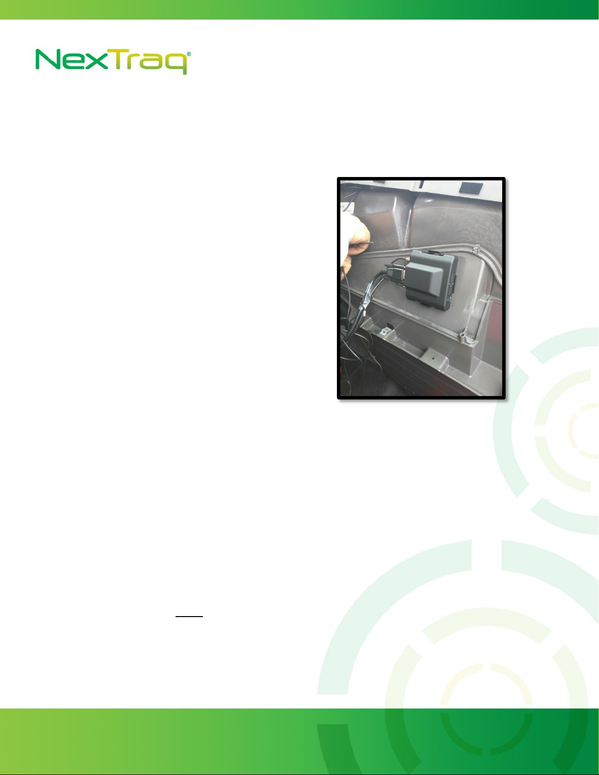
3. Locate the 9 pin Deutsch Y-cable
included in the installation kit. Locate
the end of the cable that is the same
as the factory connector that was
removed in step 2. This end will
replace the factory connector in the
housing.
4. Use the other end of the Y-cable and
mate it with the factory connector
that was removed in step 2. The
connection will need to be firmly
pushed together and the locking ring
will need to be rotated until it locks to
complete the connection. The
connector mated with the factory
connector will need to be tucked
away, or zip tied in place. Final
connector installation should look
similar to that in Figure 2.
Figure 1
1200 Lake Hearn Drive, Suite 500, Atlanta, GA 30319 | T: 678.762.6800 | F: 678.762.6805 | nextraq.com
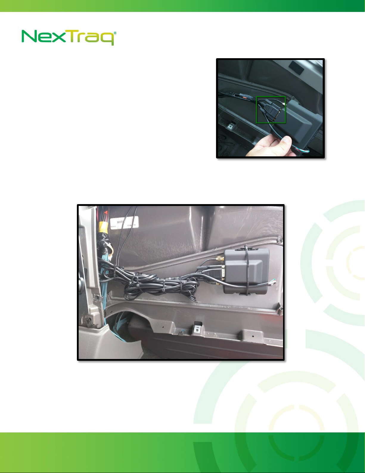
Figure 3
5. The other end of the Y-Cable contains a 15 pin connector that will be connected to the
tracking device later. The wire will need to fed to the location where the tracking device
will ultimately be securely mounted to the vehicle.
6. Where possible securely mount the
tracking device bracket to the vehicle.
Clip the tracking device into the
bracket. See Figure 3.
7. Locate a true ignition wire for the
vehicle. This must be a true ignition
source and not an active line when the
key is in the accessory position. Use
the 3-wire harness provided in the
installation kit to wire the white wire
to the ignition line.
8. Locate a true ground and wire the
black wire to it.
9. The red wire is not used and can be clipped and/or tapped securely out of the way. The
device will utilize the Y-Cable for constant power.
10. Attach the 4pin wiring harness to the 4pin connecter on the tracking device.
11. Locate the serial wiring harness provided in the installation kit. It has a 1x4 connector on
one end and an RJ45 connector on the other. Connect the 4pin connector into the tracking
device into the AUX2 port. The RJ45 end will be attached to the mounting bracket of the
tablet. Installation location of tablet needs to be verified with the customer.
1200 Lake Hearn Drive, Suite 500, Atlanta, GA 30319 | T: 678.762.6800 | F: 678.762.6805 | nextraq.com
Figure 4
Figure 5
12. Connect the 15 pin connector that is
part of the Y-Cable from step 2 to the
tracking device. See Figure 4.
13. Attach the provided antenna to the
device and mount with the “this side
up” label facing the sky with as much
of a clear/unobstructed view as
possible.
14. Once fully installed and properly mounted the tracking device should look similar to the
example install in Figure 5.
15. Attach the tablet mounting bracket to the tablet. The mounting bracket includes two
security screws. Use these screws to secure the tablet to the bracket.
1200 Lake Hearn Drive, Suite 500, Atlanta, GA 30319 | T: 678.762.6800 | F: 678.762.6805 | nextraq.com
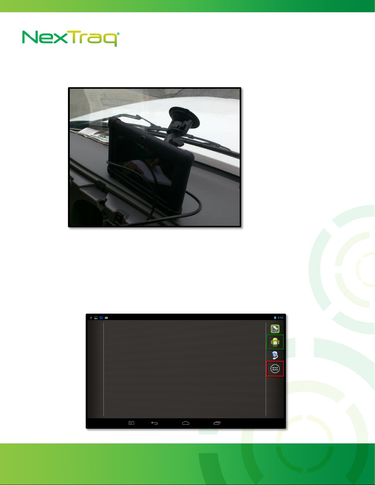
Figure 7
Figure 6
16. Attach the RAM mount to the tablet in accordance with customer installation location
preference and mount the tablet to the vehicle. See Figure 6.
17. Attach the RJ45 connector into the back of the tablet.
18. Verify that the MDT unit is connected to the LMU tracking device by checking the
connection status in the VehicleDataServices app highlighted in Figure 7 with the green box.
In the event that the VehicleDataServices app is not located on the dashboard you can locate
it under All Apps highlighted with the red box in Figure 7.
1200 Lake Hearn Drive, Suite 500, Atlanta, GA 30319 | T: 678.762.6800 | F: 678.762.6805 | nextraq.com
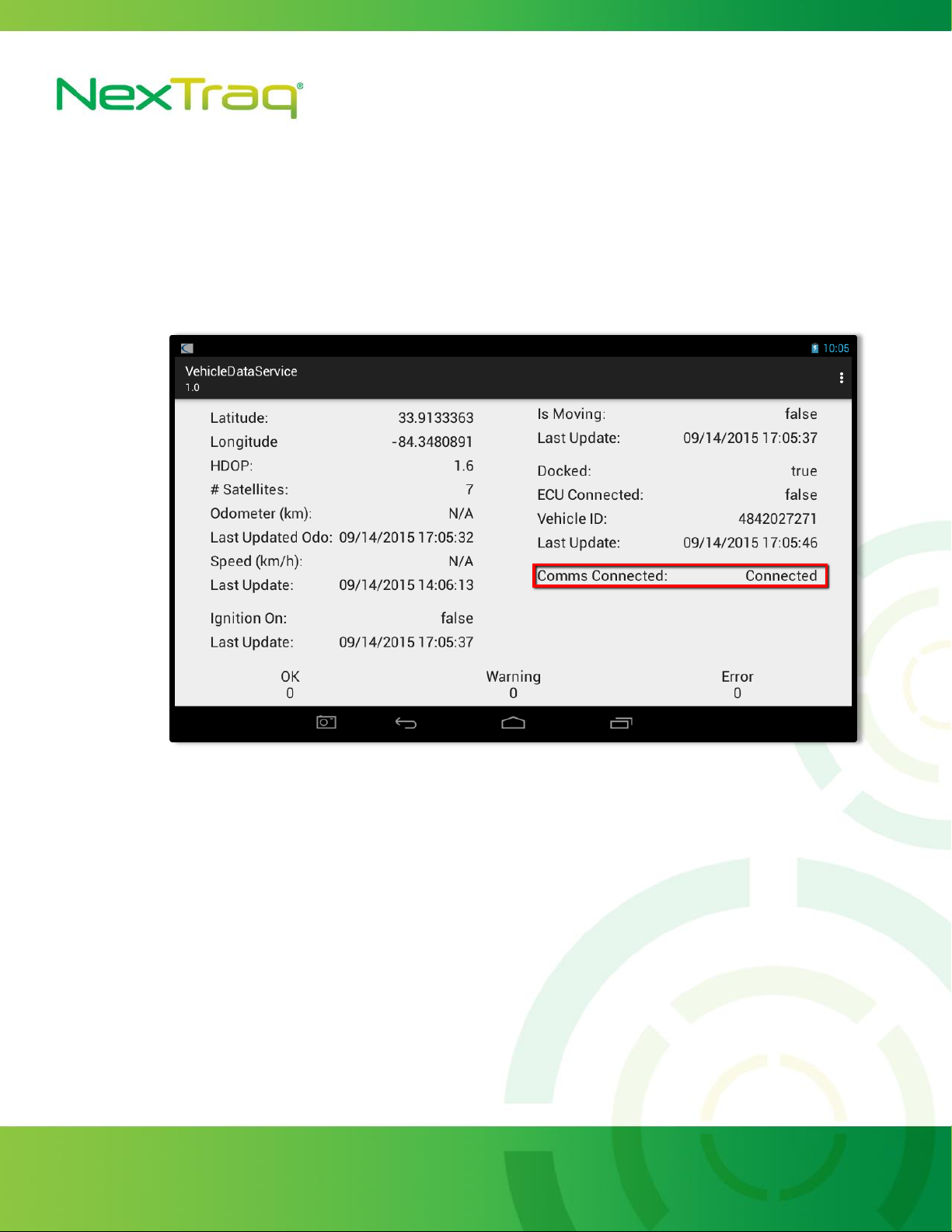
Figure 7
19. Under VehicleDataServices you should see a connected status. If the MDT is communicating
with the LMU. An ignition cycle may be required for the MDT to register a connection. See
Figure 8.
20. Verify with NexTraq Customer Support that the VT-4225 is operational
NexTraq Customer Support: 1-800-358-6178 or 678-746-6850
Customer Service Hours:
Monday-Friday 7:00am to 8:00pm (Eastern Time)
Saturday-Sunday 8:00am to 4:00pm (Eastern Time)
21. After the device passes testing by Customer Support re-seal any parts of the vehicle that
have been removed and clean up installation.

1200 Lake Hearn Drive, Suite 500, Atlanta, GA 30319 | T: 678.762.6800 | F: 678.762.6805 | nextraq.com
Installation Troubleshooting
VT-4225 will not power up.
Check connection to power supply.
Check fuse holder for voltage.
Check the voltmeter to confirm that there are 12-volts on the red power wire at the plug
end.
Make sure the unit is properly grounded snugly to a non-painted metal surface (chassis
ground).
GPS light not on or blinks.
Check GPS antenna connections and location.
Ensure that nothing obstructs antenna’s view of the sky.
Check the antenna cable for pinching or crimping.
Reset power.
COM light not on or blinks.
Check COM antenna connections and location.
Ensure that nothing obstructs the antenna such as metallic sunscreens.
Check antenna cable for pinching or crimping.
Ignition flag does not appear on NexTraq Platform
Test the circuit used for ignition voltage with a digital voltmeter.
Ensure ignition is wired to a true ignition source and not an accessory.
Vehicle will not appear in NexTraq Web application when verifying operation.
Check to see if the device has GPS and COM lock (Solid green and amber lights).
Check wiring on device. Bad constant power sources or grounds can cause rapid power cuts
preventing the device from locking COMM and/or GPS.
Be sure to view the correct mobile in the NexTraq Web application.
Check antenna connections and placement.
Table of contents
Other NexTraq Automobile Accessories manuals


