FOR REPLACEMENT COOKTOP INSTALLATION INSTRUCTIONS G9 TO SECTION D
SECTION C - CABINET CONSTRUCTION - NEW INSTALLATIONS -
THE FOLLOWING INSTRUCTIONS ARE FOR NEW INSTALLATIONS ONLY.
All cooktops are designed for installation in a base cabinet with
a countertop depth of 24”. For information on top cabinet loca-
tion see notes below.
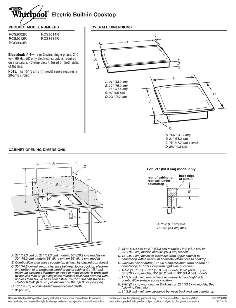
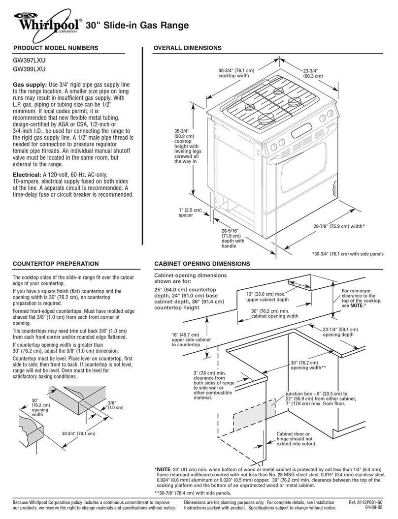
Countertop cutout dimensions are given in Figure 1. When the
illustration is followed the required clearances from the front edge
of countertop and the nearest vertical and rear walls will be
obtained.
NOTE: To eliminate the risk of burns or fire by reaching over the heated surface
elements, cabinet storage space located above the cooktop should be avoided.
If cabinet storage is to be provided, the risk can be reduced by installing a range
hood that projects horizontally a minimum of 5 inches beyond the bottom of the
cabinets.
NOTE: “A” = 30 Mmin. clearance between the top of the cooking surface and
the bottom of an unprotected wood or metal cabinet.
“A” = 24” min. when bottom of wood or metal cabinet is protected by not less
than 114” flame retardant millboard covered with not less than No. 28 MSG sheet
steel, 0.024” aluminum, 0.015” stainless steel or 0.020” copper.
BASECABINET’
CUT-OUT DIMENSIONS FOR NEW
INSTALLATION INFORMATION
Flg.
1
CONTINUE INSTALLATION INSTRUCTIONS WITH SECTION E - INSTALLING UNIT
SECTION D - CABINET CONSTRUCTION - REPLACEMENT INSTALLATIONS
THE FOLLOWING INSTRUCTIONS ARE FOR REPLACEMENT INSTALLATIONS ONLY.
All cooktops are designed for installation in a base cabinet with
a countertop depth of 24”. For information on top cabinet loca-
tion see notes below.
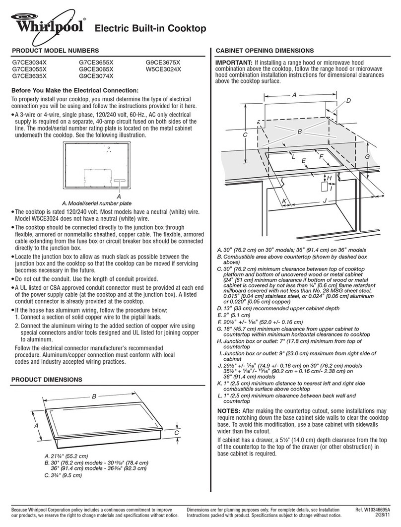
The minimum and maximum countertop cutout dimensions are
given in Figure 2 and chart below. The side wall clearances in
the diagram are recommended clearances.
IMPORTANT NOTE:
In order to comply with UL safety standards
the front edge of the cooktop must be a minimum of l-112” from
the front edge of the countertop. See Figure 3.
NOTE: To eliminate the risk of burns or fire by reaching over the heated surface
elements, cabinet storage space located above the cooktop should be avoided.
If cabinet storage is to be provided, the risk can be reduced by installing a range
hood that projects horizontally a minimum of 5 inches beyond the bottom of the
cabinets.
NOTE: “A” = 30” min. clearance between the top of the cooking surface and
the bottom of an unprotected wood or metal cabinet.
“A” = 24 ” min. when bottom of wood or metal cabinet is protected by not less
than 114” flame retardant millboard covered with not less than No. 28 MSG sheet
steel, 0.024 ” aluminum, 0.015 II stainless steel or 0.020 ” copper.
COUNTERTOP J
&SE CABINET
CUT.OUT,OIMENSION FOR REPLACEMENT
INSTALLATION INFORMATION
Fig. 2
KECT 365’ KECT 305’
