8
Heating Cycle
Upon heating demand, the thermostat closes circuit R to Y, which
closes the heat pump contactor, starting the compressor and
outdoor fan. The reversing valve is not energized in the heating
mode. The thermostat again automatically brings on the indoor
fan at the same time. Upon satisfying heating demand, the
thermostat opens the above circuits and stops heat pump
operation.
Defrost Cycle
If the outdoor ambient conditions are such that frost forms on the
outdoor coil, the defrost control monitors a defrost cycle. It then
runs the defrost cycle as ambient temperatures require.
The defrost control is time/temperature initiated and temperature
terminated with a maximum defrost time (time-out) of 10 minutes.
The time between defrost cycles is preset at 60-minute intervals
at the factory, but can be field adjusted between 30, 60, or
90 minutes. To adjust the time period between defrost cycles,
see “Adjust Time Between Defrost Cycles” in the “Circulating Air
Blower” section.
The defrost control will initiate a defrost cycle when the selected
time period has elapsed and the defrost sensor sees a
temperature below freezing. At the start of a defrost cycle, the
defrost control will energize the reversing valve solenoid, shifting
the reversing valve and de-energizing the outdoor fan. The
defrost relay will also close, energizing temporary heat for
increased comfort during defrost (if the indoor unit is so
equipped). The heat pump will remain in defrost until the defrost
sensor has determined that the frost has been removed from the
coil or a 10-minute period has elapsed, whichever comes first.
Defrost Thermostat
The defrost thermostat is located on the liquid line between the
check/expansion valve and the distributor. When defrost
thermostat senses 42ºF or cooler, the thermostat contacts close
and send a signal to the defrost control board to start the defrost
timing. It also terminates defrost when the liquid line warms up to
70ºF.
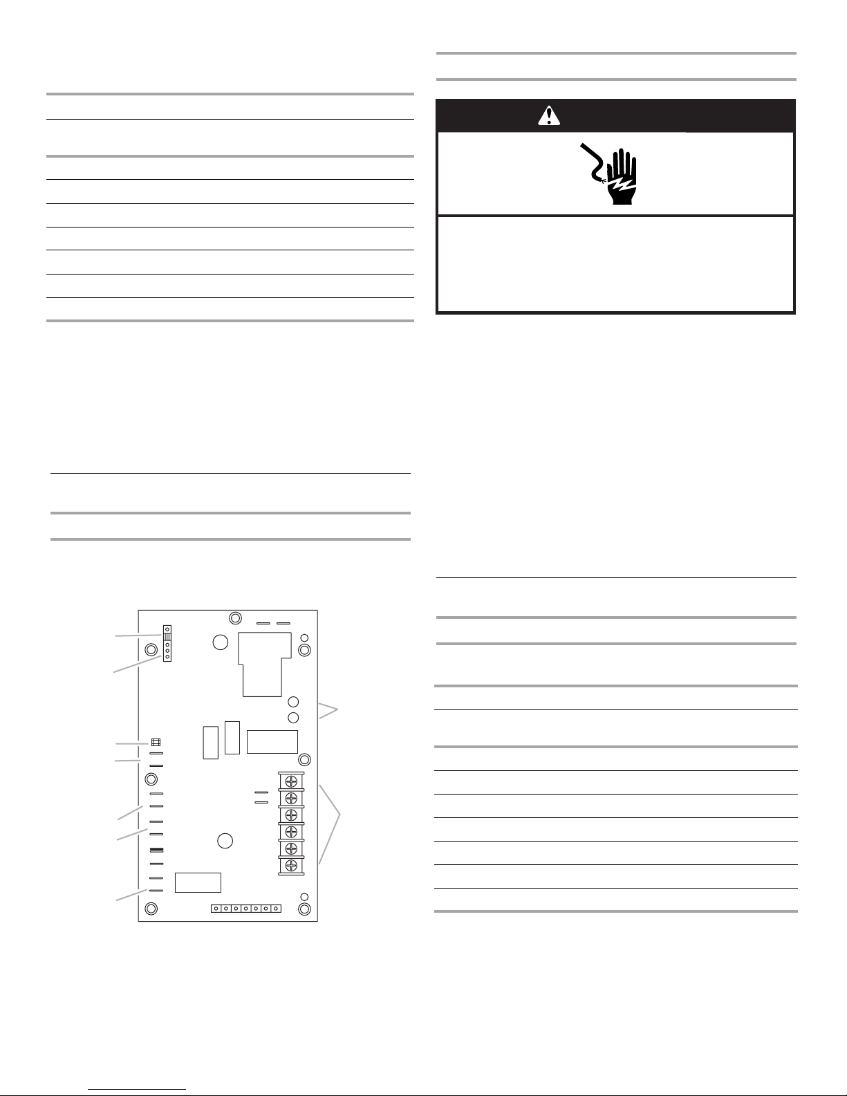
Defrost Control
The defrost control board includes the combined functions of the
time/temperature defrost control, defrost relay, diagnostic LEDs
and terminal strip for field wiring connections. See “Defrost
Control Board” in the “Adjust Defrost System” section.
The control provides automatic switching from normal heating
operation to defrost mode and back. During compressor cycle
(call for defrost), the control accumulates compressor run times
at 30, 60 or 90 minute field-adjustable intervals. If the defrost
thermostat is closed when the selected compressor run time
interval ends, the defrost relay is energized and defrost begins.
Defrost Control Timing Pins
Each timing pin selection provides a different accumulated
compressor run time period during one thermostat run cycle. This
time period must occur before a defrost cycle is initiated. The
defrost interval can be adjusted to 30 (T1), 60 (T2) or 90 (T3)
minutes. See “Defrost Control Board” in the “Adjust Defrost
System” section. The defrost timing jumper is factory-installed to
provide a 60-minute defrost interval. If the timing selector jumper
is not in place, the control defaults to a 90-minute defrost
interval. The maximum defrost period is 14 minutes and cannot
be adjusted.
A test option is provided for troubleshooting. The test mode may
be started any time the unit is in the heating mode and the
defrost thermostat is closed or jumpered. If the jumper is in the
test position at power-up, the control will ignore the test pins.
When the jumper is placed across the Test pins for 2 seconds,
the control will enter the defrost mode. If the jumper is removed
before an additional 5-second period has elapsed (7 seconds
total), the unit will remain in defrost mode until the defrost
thermostat opens or 14 minutes have passed. If the jumper is not
removed until after the additional 5-second period has elapsed,
the defrost will terminate and the test option will not function
again until the jumper is removed and re-applied.
Compressor Delay
The defrost board has a field-selectable function to reduce
occasional sounds that may occur while the package unit is
cycling in and out of the defrost mode. The compressor will be
cycled off for 30 seconds while going in and out of the defrost
mode when the compressor delay jumper is removed.
NOTE: The 30-second “off” cycle is not functional when
jumpering the TEST pins.
Time Delay
The time delay is 5 minutes long. The delay helps to protect the
compressor from short cycling in case the power to the package
unit is interrupted or a pressure switch opens. The delay is
bypassed by placing the timer select jumper across the TEST
pins for 0.5 seconds.
Pressure Switch Circuit
The defrost control includes LO-PS terminals to connect an
optional low pressure (loss of charge pressure) switch. A high
pressure switch (optional) can be connected to the HI PS
terminals. See “Defrost Control Board” in the “Adjust Defrost
System” section.
During a single demand cycle, the defrost control will lock out
the package unit after the fifth time that the circuit is interrupted
by any pressure switch wired to the control board. In addition,
the diagnostic LEDs will indicate a locked-out pressure switch
after the fifth occurrence of an open pressure switch. See
Defrost Control Board Diagnostic LEDs chart later in this section.
The package unit will remain locked out until power to the board
is interrupted, then re-established, or until the jumper is applied
to the TEST pins for 0.5 seconds.
NOTE: The defrost control board ignores input from the low
pressure switch terminals during:
■TEST mode
■Defrost cycle
■90-second start-up period
■First 90 seconds after the reversing valve switches heat/cool
modes