Whirlpool AND 040 Operating instructions

1
ENGLISH
TRANSLATIONOFTHEORIGINALINSTRUCTIONS
AND 040
I R O N I N G T A B L E
Manual drafted in compliance with EC Directive 2006/42, Annex I, paragraph 1.7.4
USER’S AND MAINTENANCE MANUAL
1 6 0 2

2
INDEX
01 -SAFETY NOTICES.........................................................................................3
02 -GENERAL DESCRIPTION AND INTENDED USE.........................................3
03 -EQUIPMENT IDENTIFICATION.....................................................................3
04 -TECHNICAL FEATURES ...............................................................................4
05 -DETAILS FOR CONNECTIONS.....................................................................4
06 -IDENTIFICATION OF MAIN COMPONENTS.................................................5
07 -IDENTIFICATION OF MAIN ACCESSORIES.................................................5
08 -CONTROL AND SIGNALING DEVICES.........................................................6
09 -PRECAUTION ................................................................................................6
10 -INSTRUCTIONS FOR USE............................................................................6
11 -HAZARDOUS USE.........................................................................................7
12 -HANDLING AND TRANSPORT......................................................................8
13 -MACHINE UNPACKING AND INSTALLATION..............................................8
14 -TROUBLESHOOTING AND SOLVING ..........................................................9
15 -MAINTENANCE PROCEDURES..................................................................10
16 -DISPOSAL....................................................................................................10
17 -HOW TO ORDER SPARE PARTS...............................................................10
18 -OVERALL DIMENSIONS AND DRAWINGS ................................................14
19 -WARRANTY.................................................................................................17

3
01 - SAFETY NOTICES
This user manual and maintenance refers to the product: Ironing table “AMBRIA”
It is possible to receive the latest release from our Technical Commercial Department.
The present user’s and maintenance manual contains important information for the operator’s health
safeguard and safety.
Read completely this manual with attention and strictly follow the procedures described in it before
installing the equipment and starting it up. Keep this manual carefully and always at the disposal of the
product operating personnel.
The manual contains the following graphic symbols that identify clearly important warnings and safety notices:
Failing to follow the indications in this manual could forfeit personnel safety!
Any possible modifications effected on the components of the machine or its different use without prior
written authorization by the manufacturer, relieve the latter of injury to persons and / or damages to
things, voiding any warranty bindings, as well.
The manufacturer cannot be held liable for any damage to things or injury to persons caused by improper
use of the machine in contrast with these instructions.
02 - GENERAL DESCRIPTION AND INTENDED USE
This equipment is intended for professional use and aimed at professionals and skilled workers.
Keep the equipment in every state (still packaged, off, running, etc.) away from children and unskilled.
The ironing table AMBRIA is completely self-contained and doesn’t require any supporting equipment for its
operation. This machine uses an external power supply for its operation.
The machine features a broad universal ironing board and (on request) a sleeve shape with vacuum (both of which
are padded and electrically heated), as well as a garment tray, a control panel to adjust the board temperature and
to operate the different work stations, a professional steam iron, a built-in boiler with automatic water feeding and
an automatic pressure control. Furthermore, it is possible to install on request a steam-air gun, a heated egg shape
and a stainless steel spotting shape.
The operation is very user-friendly and efficient, thanks to its control by pedal.
03 - EQUIPMENT IDENTIFICATION
On the side of the machine is placed an identification plate on which there is:
- Model
- Serial number
- year of construction.
- Supply voltage
- Electrical power consumption (± 5%).
- Nominal steam pressure
WARNING!
WARNING! ELECTRICAL PARTS
UNDER VOLTAGE
PROHIBITED!
PROHIBITED TO WALK
OR USE AS SUPPORT
WARNING! HOT SURFACE
KEEP THE EQUIPMENT
AWAY FROM CHILDREN

4
04 - TECHNICAL FEATURES
WARNING: The machine must not be supplied with different voltages than those indicated on the
identification plate.
(*1) According to the characteristics defined during order
(*2) Optional on request defined during order
05 - DETAILS FOR CONNECTIONS
Power supply (*1)
Boiler Steam
Sleeve
Table
3,3 - 3,9 - 4,8 - 6 kW 0,83 kW 0,14 kW 1 kW
Vacuum motor
Pump motor (*2)
Boiler volume
Steam pressure
Steam consumption
Sound intensity level
Working temperature
Working humidity
Storing temperature
Net dimension
Net weight
Overall dimensions (packaging included)
Gross weight (packaging included)
5 dm3
Power consumption ±5% (*1)
0,5 Hp
2,8 bar
2 10 kg/h
< 70 dB(A)
+ 5 + 80 C
90 % max.
- 20 + 50 °C
1550 x 580 x 950 mm. (1650 x 680 x 950 mm maxi)
87 kg (94 kg maxi)
1550 x 580 x 1120 mm (1750 x 700 x 1120 mm maxi)
103 kg (116 kg maxi)
0,6 Hp
230V – 1ph / 50 Hz
230-400V – 3ph / 50 Hz
SIMBOL
DESCRIPTION
Ø
STEAM OUTLET FOR IRON
OR ACCESSORY
Ø 6mm
WATER INLET
Ø12mm
COMPRESSED AIR
INLET
Ø 6mm
EXHAUSTED SUCTION AIR
OUTLET
Ø 90mm
ELECTRICAL CABLE INLET
PG21
BOILER DRAIN OUTLET
G 3/8”

5
01
03
05
07
08
06
02
04
01 –VACUUM PEDAL
02 –IRONING TABLE
03 –ADJUSTMENT
04 –HEATED SLEEVE SHAPE (OPTION)
05 –CLOTH FOR GARMENT TRAY
06 –STEAM IRON
07 –CONTROL PANEL
08 –MAIN DISCONNECTING SWITCH
(OPCIONAL)
05 –TECIDO SUPORTE PARA
VESTUÁRIO
06 –FERRO DE PASSAR
07 –PAINEL DE COMANDOS
08 –INTERRUPTOR SECIONADOR
06 - IDENTIFICATION OF MAIN COMPONENTS
07 - IDENTIFICATION OF MAIN ACCESSORIES
01
02
04
05
03
06
01 –IRON RAIL (OPTION)
02 –LIGHTING RAIL (OPTION)
03 –AIR-STEAM GUN (OPTION)
04 –STEAM ADJUSTMENT (OPTION)
05 –AIR ADJUSTMENT (OPTION)
06 –SMALL CONTROL CASE FOR 2ND IRON
FITTING (OPTION)

6
08 - CONTROL AND SIGNALING DEVICES
09 - PRECAUTION
Read carefully the instructions and the risks related to the use of an ironing table. The operator has to know its
working functions and must clearly understand its dangers with the help of the manual.
If the machine features a steam iron, do not leave it switched on too long and place it always on the
relevant iron rest. The ironing boards and the soleplate of the iron remain hot for some minutes after their
switching-off, please pay therefore attention to the risks of burns and do not put objects on the table until
its complete cooling-down.
Main electrical supply
Prior to carrying out any inspection or service on the machine, it is necessary to disconnect it from the
main electrical supply. Make sure, that nobody can reconnect it during the technical service.
Every installed electrical or electronic equipment must be earthed.
Inflammability
Adopt all the necessary precautions to avoid any direct contact of the machine with hot materials or
flames. Put fire extinguishers near the machine for an immediate intervention in event of fire.
Pressure / Steam
Before each intervention, switch off the boiler first and check that there are no residual pressures inside
the boiler or in any branch of the hydraulic circuit, as they could cause steam or product spurts, in case of
disassembly of fittings or other components.
Noise
The noise emission is not excessive, because it remains under 70dB(A).
10 - INSTRUCTIONS FOR USE
PUTTING INTO OPERATION
The whole unit can be used, opened and repaired by qualified technicians only.
It is forbidden to use the machine if flooded by liquids or in particularly aggressive or
explosive/inflammable places.
Always use suitable pipes according to the working pressure.
Do not ignore the dangers for the operator’s health and follow the hygienic and safety regulations.
Check that the electrical wiring is carried out correctly according to the current regulations, and that the
fuse blocks are closed and complete of fuses.
Make sure that the machine is intact.
Check that the control and safety boiler devices ( manometer, pressure switch, and safety valve) are
intact.
Make sure that the boiler discharge gate is well closed
03
04
02
01
05
06
07
08
01 - BOILER PRESSURE GAUGE
02 - BOARD HEATER THERMOSTAT
03 - WARNING LIGHT "UNDER
TENSION"
04 - 1st HEATED SLEEVE SHAPE
SWITCH (OPTION)
05 - SWITCH FOR 1st IRON
06 - BOILER SWITCH
07 - WARNING LIGHT "HEATER ON"
08 - WARNING LIGHT "PUMP
RUNNING"

7
USE WARNING: The first use of the equipment after installation or maintenance must be done on a trial basis
and regulation of all parts and accessories using tissues or garments not important. Some parts of the
machine may leave halos or spots as used for the first time. This situation may also not occur but is not a
fault.
1) Open the on-off valve of the water supply.
2) Turn on the main switch of the machine.
3) Press the boiler button.
4) The warning light of the water supply switches on automatically (the water starts running into the boiler).
5) Once the water has reached the required level the relevant warning light switches off automatically, whereas the
one of the boiler heater turns on.
6) After a few minutes the boiler reaches the working pressure of 2.6 bar (check the pressure on the pressure
gauge), the relevant warning light switches off automatically.
7) The generator is now ready to supply steam.
8) Adjust the board temperature by means of the thermostat wheel.
9) Wait until the boards reach the required temperature.
10) Push the pedal to put the air suction on boards into operation.
11) At the end of the work, turn off the table by means of the relevant buttons.
USE OF THE SLEEVE SHAPE
12) By drawing the sleeve shape towards the ironing surface, Push the pedal for the vacuum operation.
USE OF THE STEAM IRON TYPE ”U”
13) Turn on the iron switch.
14) Switch on the iron a few minutes before you start working, until the soleplate has reached the adjusted
temperature.
15) In case the temperature of the soleplate has to be kept very high, we recommend to apply a Teflon® shoe in
order to prevent burns of the garment.
USE OF THE STEAM-AIR GUN
16) Place the garment to be treated onto the spotting shape, making sure that it lies exactly on the vacuum part.
17) Push the vacuum pedal; by turning the condensation-jet of the gun first towards a tank until only steam comes
out.
18) Draw the gun closer to the part to be treated, by pushing at the same time both the vacuum and the steam
pedal.
19) Once the stain is dissolved, dry the treated part by pushing simultaneously the vacuum pedal and airbutton on
the gun.
11 - HAZARDOUS USE
The conformity verification, according to the essential safety rules and to the provisions of the machine directive,
has already been carried out by filling out the specially provided checking lists that are included in the technical file.
The checking lists are of two kinds:
List of dangers (drawn from EN 1050 referring to EN 292)
Application of the main safety features (Machine Directive–appendix. 1, part 1)
The dangers described in the following have not been completely removed, but they have been deemed to
be acceptable:
During the maintenance operation there could be some steam jets at low pressure, (maintenance
operation must therefore be carried out by using suitable protection devices)
The user must provide for a protection against direct and indirect contacts.
- SAFETY SHOES.
- VISOR FOR PROTECTION.
- PROTECTIVE GLOVES.

8
12 - HANDLING AND TRANSPORT
Before its shipment, the machine is carefully packed in a carton box or in a wooden frame. During the shipment
and storing of the machine, pay particular attention to the upside indication on the packaging. Upon receipt, please
check that the packing is intact and store the machine in a dry place.
13 - MACHINE UNPACKING AND INSTALLATION
ATTENTION: The unit must be installed, opened and repaired by fully qualified technicians only.
If the unit has been damaged externally during transport, may have suffered internal damage to its
components. Check the integrity of the machine before installation.
UNPACKING:
Find the most suitable place where to put the machine, then remove the packaging. Make sure that the machine
has not been damaged during the transport and the storage.
The packaging material does not require any special precautions for its disposal, for it is not dangerous or polluting
at all. Please refer to the local regulations for its disposal.
INSTALLATION:
The machine does not need to be anchored to the floor, except for istallation on self-moving means, where it is
necessary to use the holes on the base for the right fixing.
For a correct use and operation, as well as for an easy maintenance, leave a free space around the
machine
Do not install the machine in dangerous and/or inflammable places and/or unsuitable places.
Do not install the equipment on a inclined pavement or on unstable supports interposed between the
machine and the floor, danger of overturning.
Do not step on and not to use the equipment and its work plans as a ladder to reach the high points, and
generally do not use it as a support tool. Risk of damage and injury.
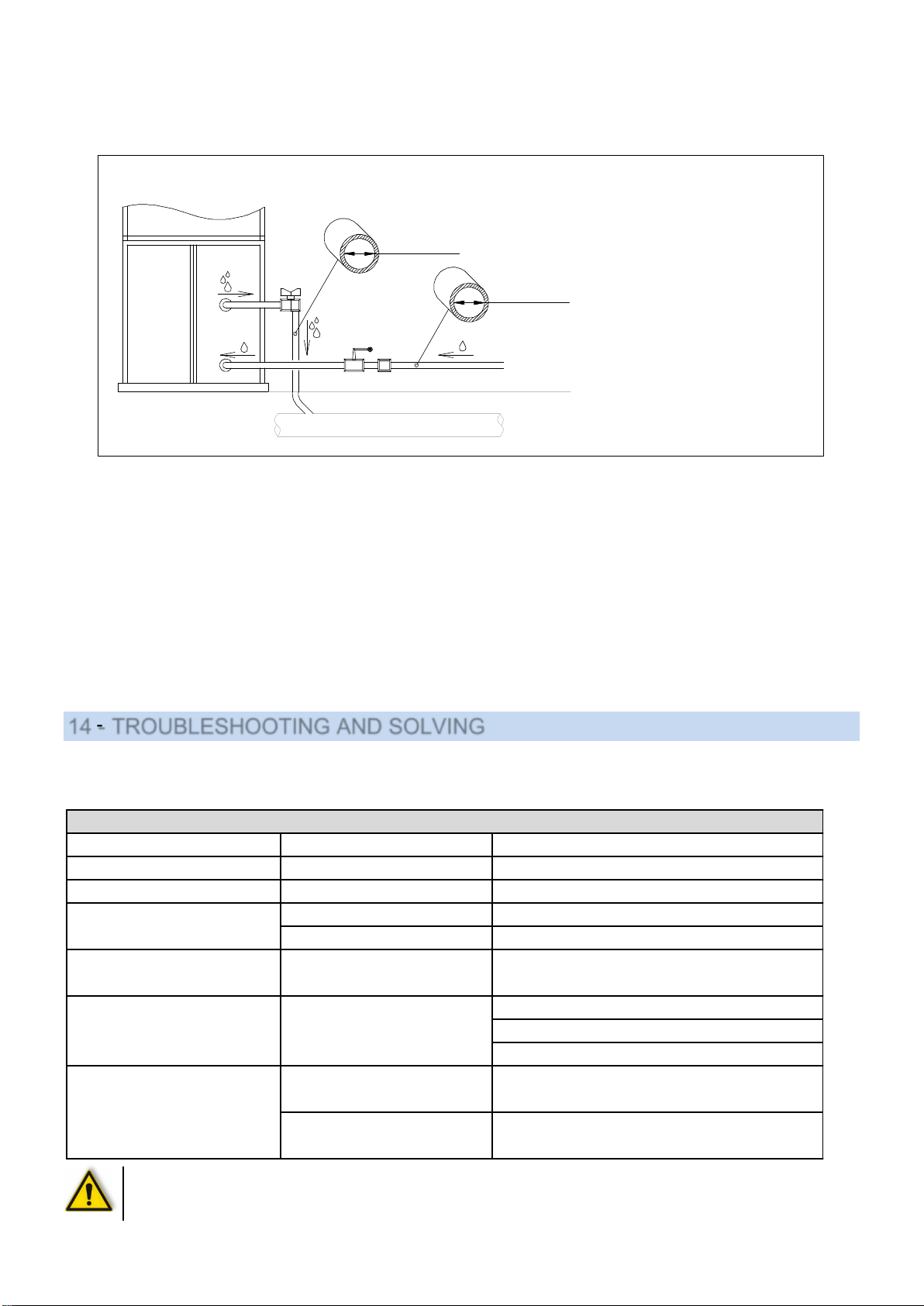
ELECTRICAL WIRING:
The electrical wiring must be carried out as indicated in the drawing. Check that the supply voltage and the
frequency correspond to those indicated on the rating plate.
The dimensions of the supply cable must suit the machine absorption and
comply to the current regulations.
For connect the equipment to the line the cable must be fitted with a suitable
industrial type plug.
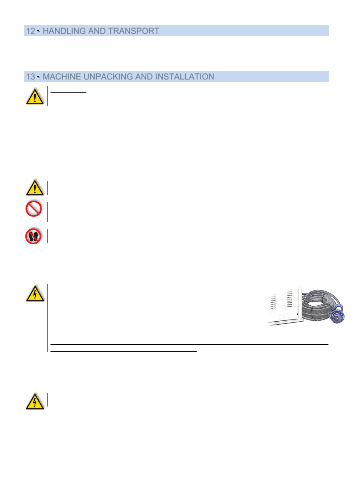
It is advisable to wrap around the cable with some straps and hold the skein
adjacent to the machine during all phases of installation and maintenance (see
figure), so be sure the equipment is physically disconnected from the power
line and that no one can accidentally reconnecting it.
Cut the straps and connect the line only after finishing all installation or maintenance operation, the
equipment must have mounted all the protection panels
It is advisable to install a switch with fuses or a magnetothermal one.
Put the cable in the cable passage hole, then tighten. Connect the cable to the terminals of
the feeder line on the control panel, as shown on the drawing of the present manual.
Check the rotation direction of the motors; if not correct, invert two of the three input phases with each other.
After all the connections to make sure that the power cables are properly secured and protected from
shocks and from contact with hot and/or sharp surfaces.

9
WATER AND OUTLET BOILER CONNECTION (only for machines with boiler)
Connect the water pipe to the hose holder of the machine. Assemble an intercepting valve and a filter on
the water feeding pipe. The water inlet has to be closed every evening to avoid eddies in the boiler. Connect the
boiler outlet to the gate valve to the drain.
COMPRESSED AIR CONNECTION: (OPTION)
Connect the machine to a central compressed air using the appropriate input, the internal diameter of the pipe must
not be lower than that indicated.
Use an intercepting valve to stop the feeding in case of maintenance and at the end of work.
Verify that system pressure is between the operating values suggested for the equipment, otherwise install a
pressure reducer.
CONNECTION OF AIR AND STEAM DISCHARGE (only for equipment with suction blower)
It is advised to discharge the air suctioned by the working planes to the outside of the working place by connecting
a pipe to the suction blower outlet. This pipe must have suitable length and diameter in order not to alter equipment
working.
14 - TROUBLESHOOTING AND SOLVING
The following diagnostic table reports the main problems which might occur, their probable causes and possible
solutions. In case of doubts and/or unsolvable problems using this table, do not look for the malfunction by
dismantling the equipment or by proceeding by attempts, but contact the Technical Office or reseller.
ATTENTION: if the safety valves is released, switch the boiler immediately off and contact a qualified
technician. Do not block the exhaust and do not underestimate the problem, as there could be risk of
explosion.
PROBLEMS POSSIBLE CAUSES SOLUTIONS
No suction on the boards Micro-switch of the pedal defect Replace the micro-switch
The boards do not heat up Thermostat defect Replace the thermostat
Main switch not on Check if the main switch is on and the fuses.
Switch turned off Turn on the switch
No steam is coming out Iron or boiler switch not turned on. Turn the switches on
Check if the water cock is open.
Check the presence of pressure inside the water mains.
Check if the water filter is obstructed.
Leak on the boiler exhaust Check if the gate valve of the boiler exhaust is well closed.
Burnt heater or covered with scale Check the heater condition.
No water is streaming into the boiler
The machine doesn’t turn on
The water warning light is turned
on and the water pump keeps on
running without stopping
The heater warning light is always
switched on and the boiler
doesn’t reach the working
pressure
DIAGNOSTIC TABLE
(3)
Ø 8mm
A)BOILERDRAINOUTLET
B)WATERINLET
1)INTERCEPTINGVALVE
2)WATERFILTER
3)GATEVALVE
4) DRAIN
(2)
G 3/8”
(B)
(A)
AMBRIA
(1)
(4)

10
15 - MAINTENANCE PROCEDURES
In case of irregularities or malfunctioning, please contact the service technician for the relevant checks.
Periodically, it is necessary to carry out the following operations:
(*): Discharge the boiler once it has reached 1 bar of pressure, in order to remove any limescale or dirt deposits.
When the machine is switched off, open slowly the gate valve of the boiler exhaust. We recommend to carry out
this operation before you start working and not in the evening at the end of work, as the fresh water streaming into
the boiler is rich in oxygen, increasing during the night the corrosion process inside the drum.
This machine does not require special equipment for check and/or maintenance operations. It is however advisable
to use suitable tools and personal protections in compliance with the Italian law by decree 626/94, which have to be
in good conditions (Presidential Decree 547/55), in order to avoid any damages to persons or machine
components.
Make sure that the power and hidraulic supply are disconnected prior to any maintenance service
and that the whole equipment is cooled down.
16 - DISPOSAL
During the maintenance on the machine, or in case of its scrapping, please dispose carefully and correctly of any
polluting components, according to the local regulations. In case of scrapping, the identification rating plate and any
other document have to be destroyed.
17 - HOW TO ORDER SPARE PARTS
Upon the spare parts request, please quote always:
Machine type, serial number, quantity of the requested spare parts, article number (these data can be read on the
rating plate or supplied by the technical information of the machine and by the user’s and maintenance manual).
For electrical components with a different voltage and frequency than V 230-380 50Hz (data available on the rating
plate of the faulty component), specify the right voltage and frequency after having mentioned the article number.
The technical data, the descriptions and pictures included in this manual are not binding. The manufacturer
reserves the right to make any necessary modification without notice or having to up-date the present manual.
OPERATION WORKING HOURS
Boiler discharge (*) 40
Cleaning of the water filter 1500
Cleaning both of boiler and heating elements 2500
Cleaning of the condensation return filter 500

11
The following are the main machine components:
Pos
Cod.#
DESCRIPTION
Pos
Cod.#
DESCRIPTION
Pos
Cod.#
DESCRIPTION
1
534269
Antenna for cable
25
24A011
Or-ring
46
36E006
Hose holder Ø12mm
2
Z01L10
Steam iron
26
162114
Universal table
47
42A002
Vacuum motor 230V / 50-60Hz
3
Z23C01
Electric cable
27
39B012
Solenoid valve for steam gun
48
42H002
Vacuum fan Ø180x72
4
43H006
Iron plug by Ilme
28
39H043
Coil for steam gun solenoid valve
49
340017
Vacuum fan wheel box
5
07A001
Steam tube
29
Z07A00
Steam gun
50
173470
Safety cover
6
39H043
Coil for steam iron solenoid valve
30
244236
Flange gasket Ø135mm
51
202128
Boiler
7
39B012
Steam solenoid valve for iron
31
212061
Boiler heater 3,9 kW
52
49A002
Automatic level control
8
43G004
Iron socket by Ilme
212060
Boiler heater 3,3 kW
53
244236
Flange gasket Ø135mm
9
173441
Small control case for 2nd iron fitting
212063
Boiler heater 4,8 kW
54
45G012
Pressure switch 2,8 bar
10
43A020
2nd iron switch
212062
Boiler heater 6 kW
55
25A001
Iron rest out of silicone
11
46C002
Power supply inlet PG21
32
07A002
Steam tube out of silicone
56
340019
Sleeve shape
12
-
33
38W001
Check valve
57
213113
Sleeve shape heater
13
Z18000
Complete fitting for second iron
34
39B036
Water solenoid valve
58
173323
Sleeve shape plate
14
35A015
Pressure gauge
35
39H015
Coil for water solenoid valve
59
Z27P14
Sleeve shape cloth
15
38S001
Safety valve
36
-
60
Padding and net for sleeve shape
16
43G005
Socket for heated shape by Ilme
37
173329
Plate out of stainless steel
61
43A020
Sleeve shape switch
17
213005
Table heater
38
184466
Rod for stainless steel plate
62
43A014
Iron switch
18
161020
Perforated plate for universal table
39
52C003
Knob
63
43A043
Main switch
19
Z27P11
Padding and cloth for maxi table
40
175103
Vacuum pedal
64
43A016
Boiler warning light
20
Z27P31
Padding and cloth
41
-
65
45A010
Table thermostat
21
37A010
Gate valve for boiler exhaust
42
43D002
Vacuum micro-switch
66
43A046
Voltage warning light
22
274203
Cloth for garment tray
43
42B030
Water pump 230V / 50Hz
67
43A014
Boiler switch
23
175005
Garment tray
44
42G021
Pump condenser MF 10
68
43A016
Water warning light
24
161037
Stainless steel rail
45
174356
Water filter

12
AUTOMATIC LEVEL CONTROL
IRON AND LIGHTING RAIL
Pos
Cod.#
DESCRIPTION
Pos
Cod.#
DESCRIPTION
Pos
Cod.#
DESCRIPTION
1
Z01L15
Steam iron
11
173304
Track L150
20
46R005
Cable holder
2
534264
Spring
173024
Track L178
21
244244
Gasket 30x7x3
3
54A001
Balancing device
12
173028
Upper column
22
43K005
Switch box
4
51X010
Ring
13
202031
Condensation separator
23
43A003
Switch
5
174022
Bracket
14
275005
Insulator for condense vessel
24
43H007
Plug
6
234078
Complete wheel
15
174520
Accessory holder
25
174017
Spacer L35
7
43C009
Lamp 36W - 230V
16
174521
Bracket for accessory holder
26
173011
Bottom column
8
43C021
Complete upper light fixture
17
39H043
Coil for steam iron solenoid valve
9
174085
Front lamp support
18
39B012
Steam iron solenoid valve
10
22A002
Bumper foot
19
175108
Supporting bracket for condensation
separator
Pos. Cod.# DESCRIPTION
1 43D014 Microswitch
2 51P007 Split pin Ø2 x 20
3 24E003 Level gasket TEFLON®
4184318 Supporting floating rod
5 49G001 Ball
6244236 Flange gasket
7183270 Flange Ø135
8183273 Flange Ø135 with ISPESL certification
9 50A016 Screw M10 x 25 ASTM-A193-B7
10 49A002 Complete automatic level

13
STEAM IRON MOD. U
Pos.
COD
DESCRIPTION
Pos.
COD
DESCRIPTION
4365
45A005
Thermostat with thermofuse
224
222056
Handle
720
184453
Fixing screw for body
223
184457
Fixing screw for handle
704
253297
Hand protection plate
222
514057
Fixing nut for body
520
224217
Hand wheel
221
514056
Nut for handle rod
519
173236
Micro-switch support
220
534288
Hand wheel spring
518
22K038
Cap for body screw
218
184455
Fixing screw for body
517
224217
Sheathing
216
172057
Handle support
516
304284
Micro-switch wires
209
514055
Nut for terminal board
515
43D009
Micro-switch complete of wires and sheathing
208
304282
Electrical wiring for thermostat heater
514
43K007
Micro-switch case
207
304281
Electrical wiring for thermostat terminal board
513
184451
Micro-switch screw
206
304280
Electrical wiring for heater terminal board
510
264350
Plate
33
224255
Cable holder for plug
406
253255
Body
31
224260
Wire clamp
405/1
174020
Thermostat column
30
224215
Little spring
402
174019
Body column
29
Z23E01
Stiffened teflon shoe
401
253254
Plate with heater
18
25A002
Water spray gun
248
184449
Isolating washers
12
224210
Cable holder
247
174018
Earth spacer
11
51X005
Clip
246
22K037
Micro-switch cap
10
Z23C00
Electrical wire
245
22K036
Nut cap
9
07A002
Silicone tube
244
514058
Nut for rear cover
8
07A001
Rubber tube
242
224245
Rubber cap for wire holder
7
43H009
Plug by Ilme
230
184448
Indented washer
6
43H002
Plug by Wieland
229
222133
Rear cover
5
174009
Jointed iron hanger
228
184450
U-bolt screw
3
364297
Cable hose
227
174353
Fixing U-bolt
1
Z23E00
Teflon shoe
225
183255
Handle rod
Power supply 220/240Vac 50/60Hz
Iron heater 0,830 kW
Working temperature + 5 + 40 C
Working humidity 90 % max.
Storing temperature - 20 + 50 °C
Net weight 1,8 kg
TECHNICAL FEATURES

14
18 - OVERALL DIMENSIONS AND DRAWINGS

15

16

17
19 - WARRANTY
All our products are supplied with a guarantee for materials and manufacturing failures for a period of maximum 12
months from the date of the delivery.
The guarantee is extended as it follows:
In case of malfunction of the machinery contact the manufacturer and quote the trouble, the model, serial
number and the operating conditions of the machine. At the receipt of the machine and after an accurate
analysis, the manufacturer reserves the right to repair or to replace the product. If the machine is still
under guarantee, the manufacturer will repair or replace it free, but if the returned product is not defective,
the manufacturer reserves the right to charge the freight to the customer (transport, etc.).This warranty
must be considered annulled in case of damages caused by an incorrect use, negligence, wear and tear,
chemical corrosion, installation in contrast with the operating instructions. Any eventual modification or
different use of the machine must be previously authorized by the manufacturer through a written
document, otherwise the manufacturer can be considered free even from the guarantee bond. The parts
of the machine which are subjected to wear and tear are not included in the guarantee. All the items not
explicitly cited or damages and expenses caused by the defects of the product itself. Implicitly the
customer accepts the conditions of the present warranty purchasing the machine. Eventual modifications
to the guarantee must be authorized by the manufacturer through a written document.
Table of contents
Other Whirlpool Iron manuals