manuals.online logo
Brands
  1. Home
  2. •
  3. Brands
  4. •
  5. Whirlpool
  6. •
  7. Trash Compactor
  8. •
  9. Whirlpool trash masher User manual

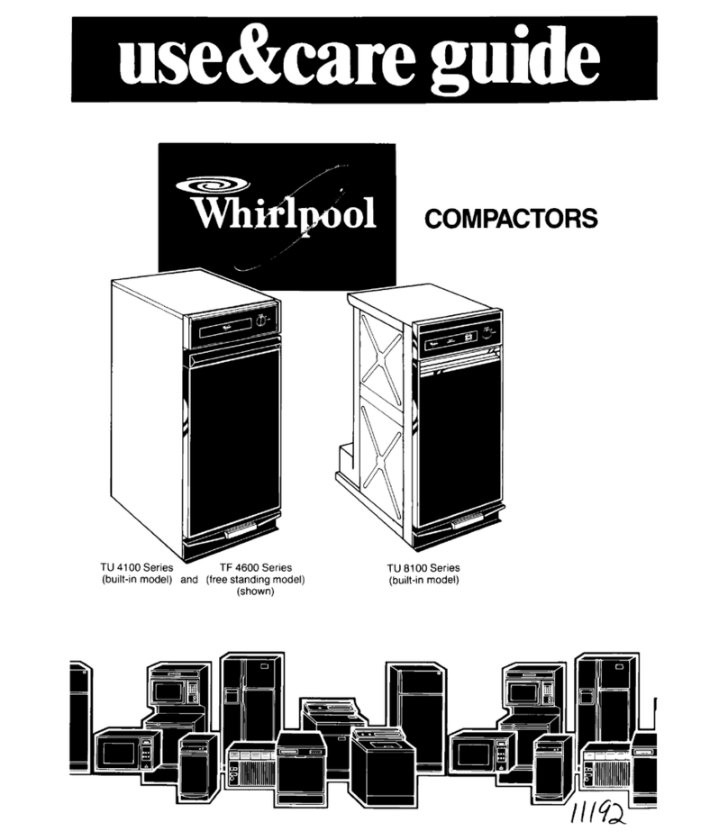
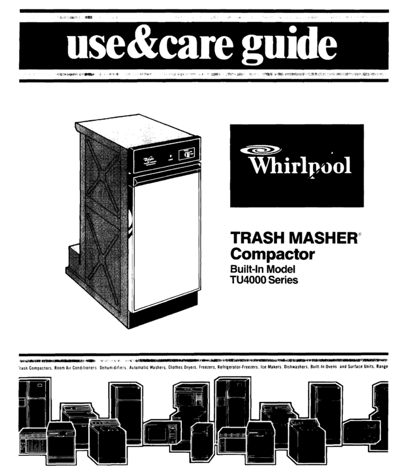
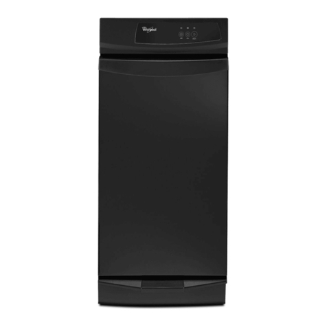
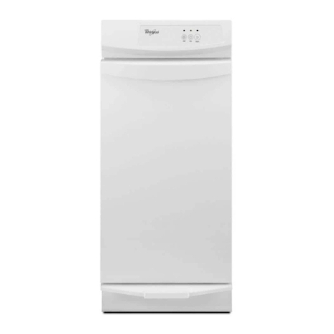
Whirlpool trash masher User manual

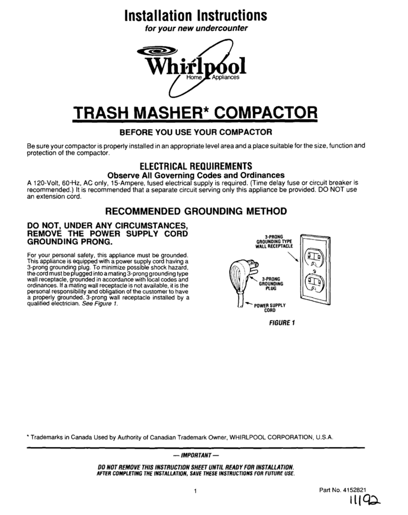
Installation Instructions
for your new undercounter
Whirlpool
TRASH MASHER@ COMPACTOR
BEFORE
YOU USE YOUR COMPACTOR . . .
Be sure your compactor IS properly installed in an appropriate level area and a place sultable for the size,
function and protectlon of the compactor
ELECTRICAL REQUIREMENTS
Observe All Governing Codes and Ordinances
A 120.Volt, 60 Hz, AC only. 15.Ampere fused electrical supply
IS
required (Time delay fuse or circuit breaker
IS
recommended ) It
IS
recommended that a separate circuit serving only this appliance be provided. DO NOT use
an extension cord
RECOMMENDED GROUNDING METHOD
DO NOT, UNDER ANY CIRCUMSTANCES,
REMOVE THE POWER SUPPLY CORD
GROUND PRONG.
3-PRONG
GROUNOlNG TYPE
WALL RECEPTACLE
For your personal safety. this appliance must be grounded
This appliance
IS
equipped with a power supply cord
having a 3-prong grounding plug To mlnlmlze possible
shock hazard, the cord must be plugged Into a mating 3-
prong grounding type wall receptacle, grounded In
accordance with the Natlonal ElectrIcal Code and local
codes and ordinances If a mating wall receptacle
IS
not
available, It
IS
the personal responslblllty and obllgatlon of
the customer to have a properly grounded 3-prong wall
receptacle Installed by a quaIlfled electrIcIan SeeF/gure 7
FIGURE I
ALTERNATE GROUNDING METHOD
(Do
not use in Canada)
DO NOT, UNDER ANY CIRCUMSTANCES,
REMOVE THE POWER SUPPLY CORD
GROUND PRONG.
If changing and properly grounding the wall receptacle
IS
lmposslble and where local codes permit (consult your
electrical Inspector). a temporary adapter may be plugged
Into the existing 2-prong wall receptacle to mate with the
3-prong power supply cord See Figure 2 THIS,
HOWEVER, IS NOT RECOMMENDED
If this
IS
done,
you
must connect the grounding eyelet on
the adapter to the wall receptacle coverplate screw and
from this same screw you must connect a separate copper
ground wire (No 18 mlnlmum) to a grounded cold water
pipe * See Figure 2 Do not ground to a gas supply pipe. Do
not connect to electrical supply until appliance Is
permanently grounded
GROUND ASSEI
./COLD WATER I
UNOEO
‘IPE)
-ELECTRICALLY GROUNDED
COLD WATER PIPE
3.PRONG -L
GROUNDING PLUG
POWER SUPPLY WALL RECEPTACLE
cd
FIGURE2
‘Grounded cold waler pfpe mu9 have metal conllnwly 10 eleclr~cal
ground and no, be Inlerrupted by plastic rubber or orher ~lrclr~cai
,nsuiatfng ~“nne~lors such as hoses htllngs washers or gaskets
(Including water meter or pump) Any eleclr~cally lnsulallng
conneclor should he Il!mped as shown below wllh a lenglh of No 4
copper wre sectirely clamped a~ holh ends
NO. 4 COPPER ~- METERg
WIRE -./
kc,
*.J/
3
CLAMPS
PETAL WATER PIPE
--IMPORTAN T-
OO NOT REMOVE THIS INSTRUCTION SHEETUNTIL READYFOR INSTALLATION.
AFTER COMPLETING THE iNSTALLATION, SAVE THESE INSTRUCTIONS FOR FUTURE L/SF.
1
Part No. 4151655
1.
2.
INSTALLATION INSTRUCTIONS
BEFORE YOU BEGIN, READ THE FOLLOWING INSTRUCTIONS COMPLETELY AND
CAREFULLY. THEY WILL SIMPLIFY THE INSTALLATION.
After removing the shipping carton, be sure to remove all
protective packaging materials such as tape and shipping pads.
Waxy residue from protective shipping material may be
removed with a mild solution of liquid household cleaner water.
Your compactor is desrgned for recessed installation.
A six (6) Inch clearance from the rrght edge of the
drawer front IS desrrable for added convenience In bag
removal Also allow twenty-three (23) Inches In front
of the appliance for drawer removal. See Figure 3.
6.
Lay two carton corner posts or other protective
material (such as a throw rug) on the floor, then lay
the unrt on either of its sides on the corner posts. The
corner posts will protect the frnrsh of the compactor
and the floor See Figure 8. NOTE: Do not truck or
handle by console
FIGURE3
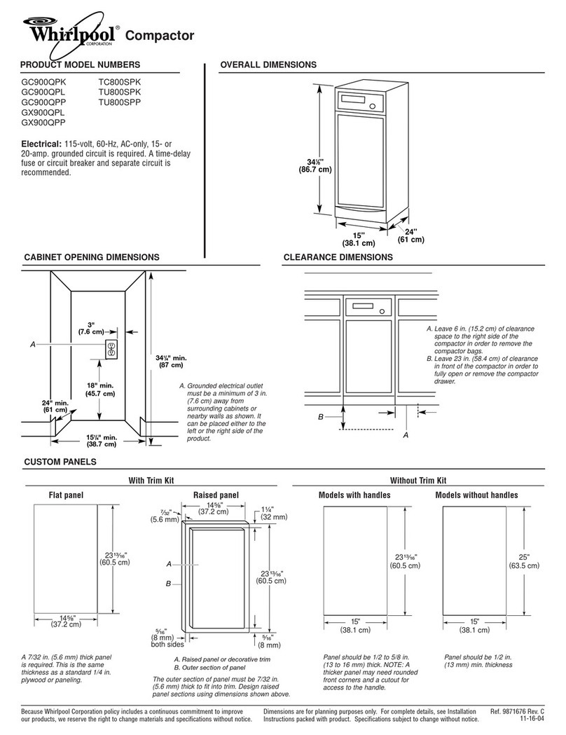
3. The compactor’s overall dimensions are: Height 337/8”
(min.), Depth 24”, Width 15”. Select a cabinet opening to
fit. See Figure 4.
3
a
1
+&.
34”
MIN.
,,
&
c
[
-
-
4.
FIGURE4
Remove drawer as shown:
a Grip handle and raise front of drawer untrl rt
clears stops. See Figure 5.
b. Grasp srde rrdges of the drawer and lrft drawer
out. See Figure 6.
FIGURE5 FIGURE6
Remove any materrals that are shipped in the drawer
Some models have a literature storage compartment
located Inside the front panel. See Figure 7. DO NOT
REMOVE THE BAG.
FIGURE8
Remove the cardboard shipping pad located on the
bottom See Figure 8. Stand compactor uprtght.
7. A grounded receptacle should be located 18” (mm )
from the floor and In the center of the opening. See
Figure 9.
1
18” (MIN.)
-
-
[
r
FIGURE9
8.
Before moving the compactor Into posrtron, measure
the cabinet openrng as shown in Figure 10. To
determrne If height adjustment IS required, see steps
9 and 10 below.
7 CABINET OPENING
m
0
FIGURE 10
9. The rear wheels of your compactor are preset for a minimum
cabinet opening of 34” (position A). To adjust for higher
openings, tilt the compactor to one side and support with
a corner post or a screwdriver handle.
CAUTION: Use care so that the compactor does not drop
on your hand.
10.
To adjust the height, remove screw from position “A”
in Figure 77. Move the rear wheel and screw to position
“B or C”:
337/B” to 343/16” use position “B”
343/116”to 34%” use position “C”
A
w
“,z
FIGURE11
Repeat for other rear wheel
2
4151655
11.
Loosen the screws In the top retaining brackets,
Rotate the brackets from shipping positron to the
Install positron. Retrghten. See Figure 72.
/ \AET*INING
BRACKETS
FIGURE12
NOTE: Position “A‘‘-Compactor frame willbe flush with
cabinets. Remove cabinet mount screws from retainmg
brackets. Save for use in step 13.
Position “B’‘-Midpoint between posltlon “A“ and “C.”
Position “C-Drawer front will be flush with cab/nets
12. When moving or lrftrng the compactor, use a glove to
protect and cushion your hand
To prevent damage to floor covering, do not allow the
rear frame of the compactor to touch the floor when
lrftlng or rollrng. /See Figure 13.)
FIGURE 13
Align the rear of the compactor with the cabinet
opening. Plug the power cord into a properly grounded
receptacle. See Figures 1, 2 and 9.
Lift the front of the compactor and roll into the
opening until the retaining brackets stop the unrt.
13. Fasten the retaining brackets to the underside of the
counter top with the screws provided. Use auxiliary
clip for fastening to cabrnet front when counter top
mounting method is not permrssrble See Figure 74.
RETAINER BRACKET
\ RETAINER BRACKET
MOUNTING CLIP
MOUNTING SCREW
COUNTER TOPMOUNTING ALTERNATECABINET FRONT
FIGURE 14
MOUNTING
Lrft the front of the compactor until it
IS
parallel with
the cabinet front Place a screwdriver or other wedge
under the front edge of the compactor.
14. Loosen the screws to the front levelers (do not remove
screws) Pivot the levelers to the floor and retrghten
screws. See Figure 15
FIGURE15
15.
Replace the drawer.
16.
The Use and Care Guide. located behind the handle of
the drawer, provides complete details for operation
and care of your compactor.
ADJUSTABLE TOE PLATE
In some Installatrons, the toe plate may rub the floor
coverrng If this occurs, the toe plate clearance may be
changed as follows:
1.
Determine the amount of Interference of the toe plate
with the floor coverrng.
2. Remove the drawer from the unn (Refer to Step 3 of
the Installation Instructions.)
3. Lay drawer so the front panel faces upward. Protect
the floor
4. Wrth a ruler and a pencrl or chalk, draw a line where
the toe plate interferes with the floor covering.
5. Use a pair of scrssors and cut toe plate along this line.
See Figure 16.
6.
Replace drawer in unit
FIGURE16
CHANGING FRONT PANEL COLOR
During installation, or in the future, you may wish to change the
front panel color. Your compactor has one reversible front panel
which offers two color options: Black and Almond.
See details of panel assembly in Figure 77.
OUTSIC
FRONT
FIGURE 17
SPACERS
DRAWER
‘TRIM
3
4151655
CAUTION: The panels have cut metal edges. Handle
carefully to avold cuts lo hands and scratches on panels.
To change the front panel color:
1.
2.
Remove the drawer from the unit. (See Step 4 of the
Installation Instructions.)
Remove handle by removing the screws at the top inside
of the drawer.
3.
4.
5.
6.
7.
Remove one spacer.
Romove outside front panel by carefully pulling it up.
Select the color you wish to have showing and carefully push
the panel in the drawer trim.
Replace the spacer.
Replace the handle with the screws removed in Setp 2
above.
8.
Replace the drawer.
CAUTION:
REPLACE HANDLE BEFORE OPERATING
COMPACTORTOAVOlDlNJURYFROMMOVlNGPARTS.
CUSTOM DECORATING
In place of the panel pack, you may use a l/4” thick wood
panel to match your cabinets or other suitable decorative
material. See Figure 78.
To do so:
1.
Follow Steps 1 through 5 under Changing Panel Color.
Also remove all cardboard.
2. Slide decorative panel between trim pieces
3. Remount handle with the screws previously removed
4. Slide the drawer Into the unit
5. Paint. wallpaper, fabric. etc., can be applied directly to
one of the panels.
1-l 14-5/B"
FIGURE 18
BEFOREYOU CALL FOR SERVICE
If
your compactor does not seem to be operating properly,
check the following before calling for service.
If the compactor won’t operate:
. Is the electric cord securely plugged in?
. Have you checked the main fuse or circuit breaker box?
. Is the drawer completely closed?
. Is the key-knob turned all the way to START before it is released?
If compactor stops during operation:
l
Push drawer in while turning key-knob to start. Repeat if necessary. Rearrange trash load - do not load rigid
items at front of drawer.
Trash not compacted:
. Drawer must be at least l/3 full to see compaction.
Not enough compaction or force:
. Compacting works best when only a few items are loaded. Use-the compacting cycle frequently.
Bottles don’t break:
. Not all bottles will break every time. depending upon trash load below It.
Drawer won’t open:
. Drawer will open only when ram is all the way up. To raise the ram, push drawer in firmly; turn key-knob to
START; release key-knob. Open drawer; lay cans and bottles flat in center of drawer. Start compactor
again.
FOR SERVICE OR PARTS INFORMATION, CALL TOLL FREE TO.
WHIRLPOOL COOL-LINE@ 800-253-7301
4151655
4

Other Whirlpool Trash Compactor manuals
Whirlpool TF 4600 Series User manual

Whirlpool

Whirlpool TF 4600 Series User manual

Whirlpool TRASH MASHER User manual

Whirlpool

Whirlpool TRASH MASHER User manual

Whirlpool [12:36:03] ?????????????????: GC900QPPB User manual

Whirlpool

Whirlpool [12:36:03] ?????????????????: GC900QPPB User manual

Whirlpool MASHER User manual

Whirlpool

Whirlpool MASHER User manual

Whirlpool GX900QPPB1 User manual

Whirlpool

Whirlpool GX900QPPB1 User manual

Whirlpool GARAGE COMPACTOR User manual

Whirlpool

Whirlpool GARAGE COMPACTOR User manual

Whirlpool TF4600X Series User manual

Whirlpool

Whirlpool TF4600X Series User manual

Whirlpool  TU950QPXS User instructions

Whirlpool

Whirlpool  TU950QPXS User instructions

Whirlpool GX900QPLQ - 15" Trash Compactor User manual

Whirlpool

Whirlpool GX900QPLQ - 15" Trash Compactor User manual

Whirlpool GX900QPPB2 User manual

Whirlpool

Whirlpool GX900QPPB2 User manual

Whirlpool  GX900QPPB User manual

Whirlpool

Whirlpool  GX900QPPB User manual

Whirlpool GC900QPPB1 User manual

Whirlpool

Whirlpool GC900QPPB1 User manual

Whirlpool TU 4000 Series User manual

Whirlpool

Whirlpool TU 4000 Series User manual

Whirlpool  GX900QPPB User instructions

Whirlpool

Whirlpool  GX900QPPB User instructions

Whirlpool 9872208 User manual

Whirlpool

Whirlpool 9872208 User manual

Whirlpool TU800SPPB2 User manual

Whirlpool

Whirlpool TU800SPPB2 User manual

Whirlpool TF 4500 Senes User manual

Whirlpool

Whirlpool TF 4500 Senes User manual

Whirlpool  TU950QPXS User manual

Whirlpool

Whirlpool  TU950QPXS User manual

Whirlpool  GC900QPPQ User manual

Whirlpool

Whirlpool  GC900QPPQ User manual

Whirlpool 220-240~volt User manual

Whirlpool

Whirlpool 220-240~volt User manual

Whirlpool TRASH MASHER User manual

Whirlpool

Whirlpool TRASH MASHER User manual

Whirlpool TU800SPPB0 User manual

Whirlpool

Whirlpool TU800SPPB0 User manual

Whirlpool Compactor User manual

Whirlpool

Whirlpool Compactor User manual

Whirlpool 4152821 User manual

Whirlpool

Whirlpool 4152821 User manual
Popular Trash Compactor manuals by other brands

Broan Elite 15XEWH Installation, use & care guide

Broan

Broan Elite 15XEWH Installation, use & care guide

Century UL 1086 manual

Century

Century UL 1086 manual

GE GE PROFILETM GCG1500L Dimensions and installation information

GE

GE GE PROFILETM GCG1500L Dimensions and installation information
GE Monogram GCG1000 manual

GE

GE Monogram GCG1000 manual

Jenn-Air W10242571C Use and care guide

Jenn-Air

Jenn-Air W10242571C Use and care guide

disperator 8075-E Service instruction

disperator

disperator 8075-E Service instruction

Viking FCU150 Service manual

Viking

Viking FCU150 Service manual

EPAX ROPAX RPM 7700 VII Original operating manual

EPAX

EPAX ROPAX RPM 7700 VII Original operating manual

ICS LT 80 Assembly manual and use and care

ICS

ICS LT 80 Assembly manual and use and care

Glasdon C-Thru Operating and assembly instruction

Glasdon

Glasdon C-Thru Operating and assembly instruction

manuals.online logo
manuals.online logoBrands
  • About & Mission
  • Contact us
  • Privacy Policy
  • Terms and Conditions

Copyright 2025 Manuals.Online. All Rights Reserved.