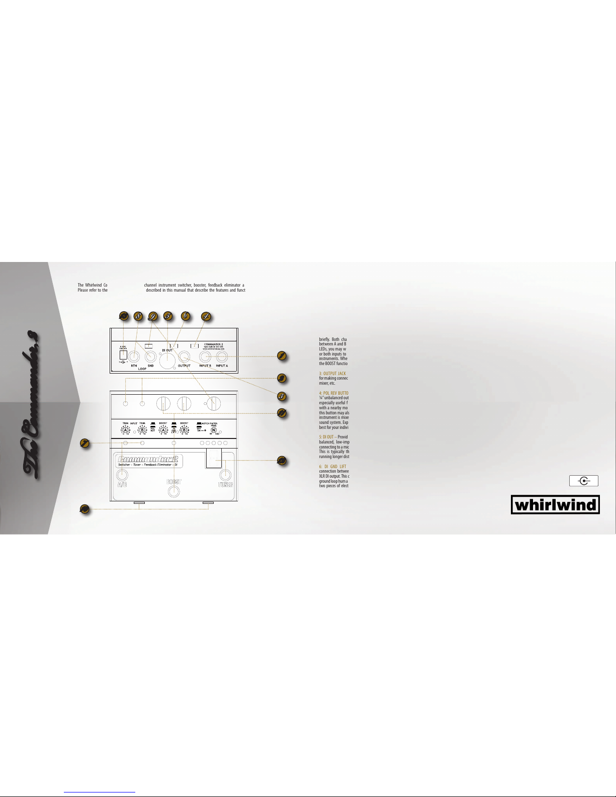
The Whirlwind Commander 2 is a two-channel instrument switcher, booster, feedback eliminator and tuner with built-in DI.
Please refer to the diagrams and features described in this manual that describe the features and functions of the Commander 2.
e Comande 2
1: INPUT JACKS A and B – Connect 2 instruments here.
Connections are for unbalanced tip/sleeve instrument
type plugs.
2: INPUT TRIM CONTROLS and LED INDICATORS – These
two trim controls are used to adjust the input level
and to balance the level between the two instruments
connected to the A and B input jacks.
Turn up the TRIM control until the loudest peaks from
each instrument cause the control shaft LED to ash
briey. Both channels may be set without switching
between A and B with the footswitch. After setting both
LEDs, you may want to ne-tune the input level on one
or both inputs to equalize the volume between the two
instruments. When doing this adjustment, be sure that
the BOOST function is turned o.
3: OUTPUT JACK is an unbalanced ¼” tip/sleeve jack
for making connections to an amplier, powered speaker,
mixer, etc.
4: POL REV BUTTON – reverses the polarity of both the
¼”unbalanced output and the XLR DI output. This can be
especially useful for reducing feedback from interaction
with a nearby monitor speaker. Changing the setting of
this button may also result in a cleaner sound when your
instrument is mixed with other band instruments in the
sound system. Experiment to nd the setting that works
best for your individual application.
5: DI OUT – Provides a high quality, transformer isolated,
balanced, low-impedance microphone level signal for
connecting to a mic input in a professional mixing console.
This is typically the output that would be used when
running longer distances down a snake to a mix position.
6: DI GND LIFT BUTTON – Disconnects the ground
connection between the ¼” output jack and pin-1 of the
XLR DI output.This can be useful for reducing or eliminating
ground loop hum and buzz that can sometimes occur when
two pieces of electronic gear are connected together. For
example, if the Commander 2’s ¼” out is connected to a
stage monitor amplier and the XLR DI out is connected to
the sound system mixer, ground interaction between the
amp and the mixer might cause ground loop noise. This
button is normally kept in the “GND” position (OUT) but
if hum or buzz is encountered, try placing the button in
the“LIFT”position (IN).
7: A/B FOOTSWITCH and INDICATOR LEDs – The footswitch
toggles the OUTPUT between the A and B INPUTS. Only
one input can be activated at a time. A corresponding LED
will light to indicate which channel is active, A on the left,
B on the right.
8: LOOP SEND and RETURN JACKS – Provide a connection
for external eects such as an outboard EQ or eects unit.
Use the SEND jack to provide the signal to the outboard
equipment. Use the RETURN jack to “return” the signal
back into the Commander 2 where it continues on to the
outputs. The RETURN jack opens an internal connection
in the COMMANDER 2 so that the signal going through
the Commander 2 is diverted through the loop. The SEND
jack by itself does not break the internal connection
through the Commander 2 and therefore can be used as
an extra output when the RETURN jack is left unused.
9: NOTCH FILTER BUTTON and FREQ CONTROL – Use this
feature to kill the howling feedback that can often occur
because of interaction between monitor speakers and
acoustic instruments, especially the lower strings on an
acoustic guitar. If you experience feedback, engage the
NOTCH button and rotate the FREQ control throughout its
range of 55 – 320 Hz. When you encounter the oending
frequency, the feedback will be notched out and disappear.
Note: The feedback elimination is accomplished by
applying a deep notch lter to your instruments signal to
reduceanarrowbandof frequenciesthatarecausingfeed-
back. The notch is very narrow so that you will notice little
or no change in the tone of your instrument. However, if
the monitor speakers are extremely loud or if you raise
the volume of your instrument or monitor, the notch may
not be able to provide enough reduction to eliminate the
feedback or a second frequency may also feed back. If this
occurs,reducethevolumelevelofinstrument and/ormonitor.
10: BATTERY - To replace the battery, turn the front
thumbscrews counterclockwise about four full turns
exposing about 1/4”of their threads. Slide the top of the
unit toward the thumbscrews as far as it will go and then
rotate it upward to expose the battery. To close the unit,
reverse the process.
11: A and B BOOST CONTROLS, BOOST FOOTSWITCH
and BOOST LED INDICATOR – Sets the amount of boost
that will be independently applied to each channel, A
or B, when the BOOST function is activated. Press and
release the BOOST footswitch to toggle the BOOST preset
function on ando.TheBOOSTindicatorLEDwill illuminate
when the BOOST is activated.
12: TUNER FOOTSWITCH and DISPLAY WINDOW – The
tuner in the Commander 2 is simple, precise, stable, fast
and easy to use with an extra bright display for tuning
under bright lights or outdoors.
Press the TUNER footswitch to activate the tuner for the
selected channel, A or B. When activated, all outputs are
muted for silent tuning. Pluck a string and the display
window will indicate the note that is being played. A
pair of dots in the upper corners of the display indicates
the sharp (#) of the note. Example, a “C” plus the dots
indicates that a C# note is detected.
Tune your string up or down until the proper note is
displayed. Once the correct note is displayed, the row
of colored LEDs above the display indicates whether
that note is sharp or at. LEDs lit to the left of center
indicate a note that is at, tune up. LEDs lit to the right
of center indicate a note that is sharp, tune down.When
the the note is in tune, both outside yellow LEDs plus
the center blue LED will light, After tuning, press the
TUNE footswitch again to turn the tuner o and turn the
Commander 2’s outputs back on. When using the
Commander 2 on battery power, it is not recommended
that you leave the tuner activated when not actually
tuning as the tuner mode draws a higher amount of
current from the battery and can shorten battery life.
13: 9-VOLT POWER INLET –Connect a standard 3.5 mm
9 Volt DC regulated supply, 100 mA capacity or greater
with a center negative plug. The Whirlwind PS9V-EFX is
recommended for proper operation.
3
5
1
2
4
6
98
11
12
7