Wieland cores C2 MB-A User manual

Thermo-
element N
DIP
(SW2)
Thermo-
element E
Thermo-
element T
Thermo-
element B
PT500
(RTD)
PT1000
(RTD)
Thermo-
element K
Thermo-
element R
Thermo-
element S
Unternehmenszentrale:
Wieland Electric GmbH
Brennerstraße 10-14
D-96052 Bamberg
Telefon +49 (951) 93 24-0
Telefax +49 (951) 93 24-1 98
www.wieland-electric.com
LED
Status
Bedeutung
PWR Grün
ON
Spannungsversorgung aktiv
PWR Grün
Blinken (Frequenz: 1/sek.)
Außerhalb Messbereich / Defekt
PWR Grün
Blinken (Frequenz: 2/sek.)
DIP-Schalter Einstellfehler
Alarm Gelb
ON
Interne Fehlermeldung
Eingang
Umgebungsbedingungen
Temperatur
-20 65 °C–
Feuchtigkeit
30 – 90 % bei 40 °C ohne Kondensation
Höhe
Bis zu 2.000 m über NN
Lagertemperatur
-20 – +85 °C
Schutzart
IP 20
Datenspeicher
EEPROM für alle Konfigurationsdateien, Aufbewahrungszeit: 40
Jahre
Spannungsversorgung
Spannung: 10 – 40 V ~, 19-28 V AC, 50 – 60 Hz
Verbrauch: max. 2 W
Elektrische Anschlüsse
4 steckbare dreipolige Schraubklemmen
Micro-USB-Anschluss an der Vorderseite
Maße / Modul Box
L: 100 mm; H: 112 mm; T: 17,5 mm
PBT. schwarz
Isolation 1500 V
Die Module wurden gemäß folgenden Normen / Richtlinien erstellt
EN61000-6-4 (Elektromagnetische Strahlung in industriellem
Umfeld).
EN61000-6-2 (Elektromagnetische Störfestigkeit in
industriellem Umfeld).
EN61010-1 (Sicherheit).
Achtung!
Eine Sicherung mit max. 2,5 A muss vor dem Modul installiert
werden.
Fehler
Genauigkeit
Thermische Stabilität
Ausgang Spannungsleistung
10 mV
0,5 mV / K
Ausgang Stromleistung
20 μA
1 μA / K
(1) Einfluss des Drahtwiderstands 0,1 V /
(2) Ausgang null für t < 250 °C.
(3) RTD Art: PT100, PT 500, NI 100
Alle Fehler müssen in Bezug auf den ohmschen Widerstand berechnet werden.
(4) Einfluss des Drahtwiderstands 0,005 % / , max. 20
μW
WW
Ausgang
Default-Einstellungen (für PC)
Eingangsart / START- und ENDE-Bereich
Spannung -10 V – +10 V
Eingangsfilter (erfasstes Signal)
Deaktiviert
Ausgangsart / START- und ENDE-Bereich
Spannung -10 V +10 V–
Stop / Sperre bei Netzfrequenz / Abtastzeit
Sperre = 50 Hz
Abtastzeit = 20 ms
Kaltstellenkompensation (für R-, TC-Eingänge)
Deaktiviert
Bestellnummer
Beschreibung
82.003.0201.0
cores C2 MB-A
F0.000.XXX.X
USB-Kabel (Konfigurationssoftware unter www.wieland-electric.com)
EINSTELLUNG VON START- UND END-WERTEN DES
MESSBEREICHS
ZUBEHÖER
2
4
10
Stromversorgung
Eingang Ausgang
1500V
7
11
10
11
mA
mA Eingang
+
10
7
mA
mA Eingang (2 Draht)
+
V Eingang
10
9
V
+
RTD 4 Draht
8
12
10
9
10
12
9
8
R
10
9
8
12
RTD 3 Draht
8
12
10
9
Stromausgang 2
mA
+
1
4
V
+
Spannungsausgang 2
Stromausgang 1
mA
+
5
6
V
+
Spannungsausgang 1
10
12
+
8
3
5
6
7
9
Filter
Der Eingangssignalfilter kann aktiviert und
konfiguriert werden (nur über PC).
von 0,5 bis 60 Sek.
Reaktionszeit
35 ms bei Auflösung 11 Bit, 140 ms bei Auflösung 16 Bit
(Messung von Spannung, Strom, Potentiometer).
Eingangsart Spannung
Bipolar von 75 mV bis zu 20 V mit 9 Skalen, Eingangsimpedanz
1 , max. Auflösung 15 Bit + Vorzeichen.W
Eingangsart Strom
Bipolar bis zu 20 mA, Eingangsimpedanz ca. 50 , max. Auflösung
1 mA, Stromversorgung vom Sensor zum Modul (passives Modul) oder
vom Modul zum Sensor (aktives Modul) über Klemme 7 (Max. 25 mA -
Max. 20 V) kurzschlussfest. Automatische Überbereichserkennung.
W
Widerstands-
thermometer (RTD)
RDT Art/Typ: PT 100, PT 500, PT 1000, NI 100, KTY 81, NTC, KTY 84
-30/-150, Widerstandsmessung mit 2, 3 oder 4 Leitern und
Widerstandsmessung der Leiter, Auslösestrom 0,56 mA,
Auflösung 0,1 °C, automatische Erkennung der Leitungsunterbrechung,
NTC Widerstandswert < 25 k NTC, KTY 81 und KTY 84 nur durch
Software konfigurierbar.
W.
Thermoelement
Typ J, K, R, S, T, B, E, N, Eingangsimpedanz > 5 M , automatische
Erkennung von Leitungsunterbrechungen, Auflösung 2,5 μV.
W
Potentiometer
Mindestspannung 300 mV, Eingangsimpedanz von 500 bis 100 k
(Parallelschaltung eines Widerstand erforderlich, s. Grafik 6). Autom.
Erkennung des Eingangswertes oder nicht verwertbarer Werte.
WW
Eingang Regler
Reglerbereich mit 500 bis max. 25 kWW
Fehler in Bezug auf den
max. Messbereich
Genauigkeit
Wärmebeständigkeit /
Wärmefestigkeit
Linearitätsfehler
EMI
TC Eingang für J,K,E,T,N
0,1 %
0,01 % / °K
0,2 °C
< 1 % (1)
TC Eingang für R,S
0,1 %
0,01 % / °K
0,2 °C
< 1 % (1)
TC Eingang für: B (2)
0,1 %
0,01 % / °K
1,5 °C
< 1 % (1)
Kaltverbindung und
Ersatz (für alle TC
Eingangsarten)
2 °C tra 0 °C
und 50 °C
Umgebungs-
temperatur
---
---
---
Widerstandsthermo-
meter (RTD) (3)
0,1 %
0,01 % / °K
t>0 °C 0,02 %
t>0 °C 0,05 %
< 1% (4)
Potentiometer oder
Regler (RTD)
0,1 %
0,01 % / °K
0,1 %
< 1 %
Eingangsart
Spannung / Strom
0,1 %
0,01 % / °K
0,05 %
< 1 % (1)
19 – 28 V ac
10 – 40 V dc
2 W Max
2
3
1
Spannungsversorgung
Die Spannungsversorgung muss zwischen 10 und 40 V liegen (unab-
hängig von der Polarität) oder zwischen 19 und 28 V~. Die Obergren-
zen dürfen nicht überschritten werden, da es sonst zu Schäden am
Modul kommen kann. Die Spannungsversorgung muss gegen
mögliches Versagen der Module geschützt werden. Verwenden Sie
dafür ein angemessen großes Sicherungselement (max. = 2,5 A).
AusgangsartSW2
Normal (OFF)
Invers(ON)
SW2 Ausgangsart
Strom (OFF)
Spannung (ON)
LED-ANZEIGEN AUF DER FRONTSEITE
KONFIGURATION MIT DEM PC
Um weitere feste Parameter zur Start- und End-Skala hinzuzufügen, benötigen Sie einen PC und eine
Software. Diese können Sie unter www.wieland-electric.com herunterladen.
Zusätzliche Eingangsarten.
Digitale Filter (normalerweise deaktiviert).
Logarithmische Funktion (normalerweise deaktiviert).
Verhalten bei Leitungsunterbrechung (normalerweise deaktiviert).
Start- und End-Skala für analogen Ausgang.
Wert des analogen Ausgangs im Fehlerfall.
Programmierbare Sperre / Stop für 50 oder 60 Hz Netzfrequenz (normalerweise bis 50 Hz).
Einstellung 3- oder 4-Draht-Techik ( PT100, PT500, Pt1000).
Die Einstellungsanweisungen und das USB-Kabel sind auf Anfrage im Set erhältlich.
default = 3-Draht;
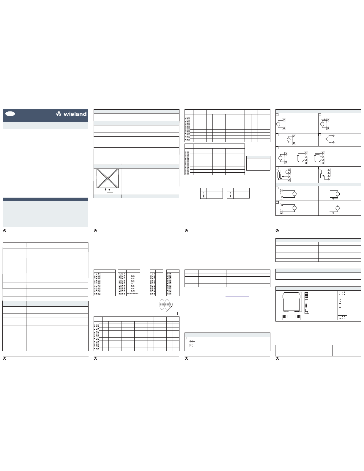
ELEKTRISCHE ANSCHLUESSE
TECHNISCHE DATEN
DE cores C2 MB-A
82.003.0201.0
Multifunktions-Wandler mit isoliertem zweipoligem Ausgang Stand: 04/2014
2014 Wieland Electric GmbH©
Abweichung von DIP-Schalter-Standard-Parametern sind durch die Konfigurationssoftware möglich.
INSTALLATIONSVORSCHRIFTEN
Das Modul wurde zur Montage auf DIN-Schiene (DIN 46277) in senkrechter Position entworfen. Für
eine optimale Funktionsweise muss eine angemessene Belüftung des Moduls gewährleistet werden.
Dabei muss vermieden werden, dass die Belüftungsschlitze blockiert werden.Bringen Sie die Module
nicht über wärmeerzeugenden Geräten an. Zu empfehlen ist die Montage im unteren Teil des
Schaltschranks.
AUSWAHL DER EINGANGSART UND DER MESSBEREICHE
Die Auswahl der Eingangsart erfolgt durch Einrichtung der Gruppe von DIP-SW1 seitlich des
Moduls. Jede Eingangsart entspricht einer bestimmten Anzahl von Skalenanfangswerten ( )
und Skalenendwerten ( ), die mit der Gruppe SW2 wählbar sind. In der nachstehenden Tabelle
werden die möglichen Werte und jede gewählte Eingangsart aufgeführt.
START
END
DIP
(SW2)
Thermo-
element J
START END START END START END
START END START END START END
1 (*) (*) (*) (*) (*) (*) (*) (*) (*) (*) (*) (*)
2 0°C 0°C 100°C 200°C 0°C 400°C 0°C 400°C
3 50°C 50°C 200°C 400°C 100°C 600°C 100°C 600°C
4 -50°C 100°C -50°C 100°C 0°C 300°C 0°C 600°C 200°C 800°C 200°C 800°C
5 0°C 150°C 0°C 150°C 100°C 400°C 100°C 800°C 300°C 300°C
6 200°C 50°C 200°C 200°C 500°C 200°C 400°C 400°C
7 100°C 300°C 100°C 300°C 300°C 800°C 300°C 600°C 600°C
8 150°C 400°C 500°C 500°C 800°C 800°C
1000°
1200°
1400°
1750°
1000°
1200°
1400°
1750°
1000°
1200°
1300°1000°400°C200°C
50°C
-100°C
-200°C
-100°C
-200°C
-100°C
-200°C
-100°C
-200°C
(*) START- und END-Werte
werden mittels Drucktaster
programmiert.
STARTSTART END START END START ENDEND
(*)1 (*) (*) (*) (*) (*) (*) (*)
2 50°C 500°C 50°C 200°C
3 100°C 600°C 100°C 400°C
4 -50°C 150°C 600°C 800°C 0°C 200°C 0°C 600°C
5 0°C 200°C 700°C 1000° 100°C 300°C 100°C 800°C
6 250°C 800°C 1200° 1500° 400°C 200°C
7 100°C 300°C 1000°C 1500° 200°C 600°C 300°C
8 150°C 400°C 400°C 500°C
1000°
1200°
1300°800°C1800°C1200°C
50°C
-100°C
-200°C
500°C
0°C
-100°C
-200°C
-100°C
-200°C
AUSWAHL DES AUSGANGS
Die SW2-DIP-Schalter der Gruppen Nummer 7 und 8 ermöglichen das Einrichten der Ausgangsart
Spannung, Strom und die Ausgabeart (normaler oder umgekehrter Ausgang).
Die Tasten START und END unter der Gruppe der DIP-SW2 ermöglichen das beliebige Einrichten
des Skalenanfangs- und -endwerts innerhalb des mit den DIP eingerichteten Messbereichs. Für
diesen Vorgang ist ein geeigneter Signalgenerator erforderlich, der in der Lage ist, die gewünschten
Werte für Skalenanfang oder -ende zu liefern.
Dabei ist wie folgt vorzugehen:
1. Stellen Sie mit SW1 die Eingangsart für das gewünschte Modul ein, stellen Sie mit SW2 einen
START- und ENDE-Messbereich ein, welcher dem gewünschten Skalenanfangs- und -endwert für
die Messung entspricht.
Modulbemaßung
Vorderes Bedienfeld
112 mm
17,5 mm
100,0 mm
PWR/ERR
x
USB
ALARM
Y
x
ABMESSUNGEN
2. Schalten Sie die Stromversorgung am Modul ein.
3. Schließen Sie einen Generator oder Kalibrator an der Eingangsklemme an.
4. Richten Sie am Generator den gewünschten Skalenanfangswert ein.
5. Betätigen Sie die Taste START für mindestens 3 sek. Ein Blinken der grünen LED auf der
Frontplatte des Moduls zeigt die erfolgte Speicherung des Wertes an.
6. Stellen Sie den benötigten ENDWERT am Generator ein.
7. Drücken Sie den ENDE-Taste für mindestens 3 sek. Ein Blinken der grünen LED auf der
Frontplatte des Moduls zeigt die erfolgte Speicherung des Wertes an.
8. Schalten Sie die Stromversorgung des Moduls ab und setzen Sie die DIP-Schalter der Gruppe
SW2 (1-6) auf OFF.
Das Modul ist für den gewünschten Skalenanfangs- und Endwert konfiguriert. Für eine weitere
Programmierung genügt es, den gesamten Vorgang zu wiederholen.
Eingang Regler:
Werte von 500 bis 25 k
werden unterstützt.
WW
Eingang Widerstandsther-
mometer: PT100, PT500, PT1000.
Der 2-Leiter-Anschluss kann
ebenfalls für NTC und KTY genutzt
werden.
Eingang
Thermoelement:
J, K, R, S, T, B, E und
N. Eingangsspannung
für Vollaussteuerung
< 150mV
Spannungseingang
(-20... +20V)
Vollaussteuerung >
150mV
Aktiver Stromeingang (-20...
+20 mA). Das Modul stellt
den Messstrom bereit. Nutzen
Sie diese Verbindung für 2-
Draht-Messung.
Passiver Stromeingang (-20...
+20 mA). Der Sensor stellt den
Messstrom bereit. Benutzen Sie
diesen Eingang bei externer
Stromversorgung.
Eingang Potentiometer:
Eine Parallelschaltung mit
ist
notwendig. Der Wert des
Potentiometers muss
1k – 100 k betragen.
R=330 WiderstandW
WW
Die DIP-Schalter müssen
eingestellt werden, wenn
das Modul abgeschaltet
ist, sonst kann es zu
Schäden am Modul
kommen.
Achtung!
DIP
(SW2)
Spannung Widerstand /
Regler
Strom Potentio-
meter
Ni100
(RTD)
Pt100
(RTD)
1 (*) (*) (*) (*) (*) (*) (*) (*) (*) (*) (*) (*)
2 0 V 0 W 1 kW 0 mA 1 mA 0 % 40 % -50°C 20°C 50°C
3 2 kW 1 mA 2 mA 10 % 50 % -30°C 40°C 100°C
41V 3 kW4 mA 3 mA 20 % 60 % -20°C 50°C -50°C 200°C
5 2 V 1 V 2 kW 5 kW -1 mA 4 mA 30 % 70 % 0°C 80°C 0°C 300°C
6 -5 V 5 V 5 kW -5 mA 5 mA 40 % 80 % 20°C 100°C 50°C 400°C
7 -10 V 10 V 10 mA 50 % 90 % 30°C 150°C 100°C 500°C
8 -20 V 20 V 20 mA 60 % 100 % 50°C 200°C 200°C 600°C
400mV
100mV
200mV
400mV 1 kW
0.5 kW
10 kW
15 kW
10 kW
15 kW
25 kW
-10mA
-20mA
-200°C
-100°C
START END START END START END
START END START END START END
V
/ Rheostat
mA
Ni100
0
Pt500
Pt1000
Tc J
W
Pt10
Eingangsarten
SW1 Eingangsarten
SW1
1
2
3
4
5
6
7
8
END
SW2
1
2
3
4
5
6
7
8
START
SW2
START-
BEREICH
END-
BEREICH
1 2 3 4 5 6 7 8
SW2
DIP-Switch in OFF-Position
Ausgangsart
Strom: -20 – +20 mA, maximaler Lastwiderstand 500
Spannung: -10 – +10 V, minimaler Lastwiderstand 1 k
μ
W
W
Auflösung: 5 A / 2,5 mV
mV/TC
Eingang
Inhalt:
Allgemeine Eigenschaften
Technische Daten
Installationsvorschriften
Auswahl der Eingangsart und der Messbereiche
Auswahl des Ausgangs
Einstellung von Start- und End-Werten des
Messbereichs
LED-Anzeigen auf der Frontseite
Konfiguration mit dem PC
Elektrische Anschlüsse
Default-Einstellungen für PC
Zubehör
Abmessungen
ALLGEMEINE EIGENSCHAFTEN
INSTALLATIONSANLEITUNG
Universal-Eingang: Spannung (mV), Strom (mA), Thermoelemente TC, Widerstandsthermometer
RDT, Potentiometer, Regler, NTC
Messung und Übertragung auf isolierten Analogausgang / zweipoligen Ausgang mit aktivem /
passivem Ausgang für Spannung und Strom.
DIP-Schalter zur Auswahl von Eingangsart, des START-END-Bereichs und Ausgangsart.
USB Anschluss für Konfiguration per PC.
Stromversorgung für externen Sensor ist verfügbar (über Klemme 7).
Galvanische Trennung (3-Wege 1500 V~).
Frontanzeige: Eingeschaltet (PWR), Konfigurationsfehler (ERR), Alarmanzeige (ALARM).
Das Gerät darf nur von einer zugelassenen Elektrofachkraft installiert, in Betrieb genommen
und gewartet werden.
Bei der Planung und Errichtung von elektrischen Anlagen sind die einschlägigen Richtlinien,
Vorschriften und Bestimmungen des jeweiligen Landes zu beachten.
Die geltenden Sicherheits- und Unfallverhütungsvorschriften sind stets zu beachten.
Beschädigte Produkte dürfen weder installiert noch in Betrieb genommen werden. Im Falle
eines Defekts senden Sie das Gerät zurück an Wieland Electric GmbH.
Nur in spannungsfreiem Zustand anschließen oder trennen!
Das Gerät darf nicht geöffnet werden.
Führen Sie keine Fremdobjekte in das Gerät ein!
Halten Sie das Gerät von Wasser und Feuer fern!
SICHERHEITSHINWEIS
BA000964 A (04/2014)
BA000964 A (04/2014) BA000964 A (04/2014) BA000964 A (04/2014)
DEUTSCH 3/8 DEUTSCH 7/8DEUTSCH 5/8
BA000964 A (04/2014) DEUTSCH 1/8
DEUTSCH 4/8 DEUTSCH 8/8
BA000964 A (04/2014) BA000964 A (04/2014) BA000964 A (04/2014)
DEUTSCH 6/8DEUTSCH 2/8
wieland
wieland wieland wieland
wieland
wieland
wieland
wieland
PT500
(RTD)
PT1000
(RTD)
Thermo-
couple K
Thermo-
couple R
Thermo-
couple S
DIP Thermo-
couple J
START END START END START END
START END START END START END
1 (*) (*) (*) (*) (*) (*) (*) (*) (*) (*) (*) (*)
2 0°C 0°C 100°C 200°C 0°C 400°C 0°C 400°C
3 50°C 50°C 200°C 400°C 100°C 600°C 100°C 600°C
4 -50°C 100°C -50°C 100°C 0°C 300°C 0°C 600°C 200°C 800°C 200°C 800°C
5 0°C 150°C 0°C 150°C 100°C 400°C 100°C 800°C 300°C 300°C
6 200°C 50°C 200°C 200°C 500°C 200°C 400°C 400°C
7 100°C 300°C 100°C 300°C 300°C 800°C 300°C 600°C 600°C
8 150°C 400°C 500°C 500°C 800°C 800°C
1000°
1200°
1400°
1750°
1000°
1200°
1400°
1750°
1000°
1200°
1300°1000°400°C200°C
50°C
-100°C
-200°C
-100°C
-200°C
-100°C
-200°C
-100°C
-200°C
Resistance /
Reostat
DIP Voltage Current Potentio-
meter
Ni100
(RTD)
Pt100
(RTD)
1 (*) (*) (*) (*) (*) (*) (*) (*) (*) (*) (*) (*)
2 0 V 0 W 1 kW 0 mA 1 mA 0 % 40 % -50°C 20°C 50°C
3 2 kW 1 mA 2 mA 10 % 50 % -30°C 40°C 100°C
41V 3 kW4 mA 3 mA 20 % 60 % -20°C 50°C -50°C 200°C
5 2 V 1 V 2 kW 5 kW -1 mA 4 mA 30 % 70 % 0°C 80°C 0°C 300°C
6 -5 V 5 V 5 kW -5 mA 5 mA 40 % 80 % 20°C 100°C 50°C 400°C
7 -10 V 10 V 10 mA 50 % 90 % 30°C 150°C 100°C 500°C
8 -20 V 20 V 20 mA 60 % 100 % 50°C 200°C 200°C 600°C
400mV
100mV
200mV
400mV 1 kW
0.5 kW
10 kW
15 kW
10 kW
15 kW
25 kW
-10mA
-20mA
-200°C
-100°C
START END START END START END
START END START END START END
LED
Status
Meaning of LEDs
PWR Green
ON
Power supply presence
PWR Green
Flashing (freq.: 1/sec.)
Out of range, Burn out
PWR Green
Flashing (freq: »2/sec.)
DIP-switchsetting Error
ALARM Yellow
ON
Internal fault
(1) Influence of wire resistances 0.1 μV /
(2) Output zero if t < 250 °C.
(3) RTD type: PT100, PT 500, NI 100.
All the errors have to be calculated with reference to resistive value.
(4) Influence of wire resistances 0,005 % / , max. 20
W.
WW.
Default settings for PC
Input type / Start – End range
Voltage -10 V – +10 V
Input filter (acquired signal)
Disabled
Output type / Start – End range
Voltage -10 V +10 V–
Rejection at mains frequency / Sampling time
Rejection= 50 Hz
Sampling time = 20 ms
Cold junction compensation ( for RTC input)
Disabled
Order Code
Description
82.003.0201.0
cores C2 MB-A
F0.000.XXX.X
USB cable (configuration software on www.wieland-electric.com)
SETTING START AND END AT WILL
Module Dimensions
Front Panel
ACCESSORIES
Thermo-
couple N
DIP Thermo-
couple E
Thermo-
couple T
Thermo-
couple B
STARTSTART END START END START ENDEND
(*)1 (*) (*) (*) (*) (*) (*) (*)
2 50°C 500°C 50°C 200°C
3 100°C 600°C 100°C 400°C
4 -50°C 150°C 600°C 800°C 0°C 200°C 0°C 600°C
5 0°C 200°C 700°C 1000° 100°C 300°C 100°C 800°C
6 250°C 800°C 1200° 1500° 400°C 200°C
7 100°C 300°C 1000°C 1500° 200°C 600°C 300°C
8 150°C 400°C 400°C 500°C
1000°
1200°
1300°800°C1800°C1200°C
50°C
-100°C
-200°C
500°C
0°C
-100°C
-200°C
-100°C
-200°C
DIP-switches must be set
while the module is
powered down, otherwise
the module may be
damaged.
Attention!
Corporate Headquarters:
Wieland Electric GmbH
Brennerstraße 10-14
D-96052 Bamberg
Telefon +49 (951) 93 24-0
Telefax +49 (951) 93 24-1 98
www.wieland-electric.com
Stromversorgung
Eingang Ausgang
1500V
(*) START or END are set
in memory with the PC or
with a programming push
buttons.
Environmental conditions
Temperature
-20 – 65°C
Humidity
30 – 90 % a 40°C not condensing.
Altitude
Up to 2.000 m a.s.l.
Storage Temperature
-20 – +85°C
Protection degree
IP 20
Data Memory
EEPROM for all configuration data; storage time: 40 years.
Power Supply
Voltage: 10 – 40 V~, 19-28 V~ 50 – 60 Hz
Consumption: max. 2W
Electrical connections
Removable 3-way screw terminals 5 mm pitch.
Micro-USB frontal plug.
Dimensions / Modul-Box
L: 100 mm; H: 112 mm; T: 17,5 mm
PBT. black.
Isolations 1500 V
The module complies with the following standards:
EN61000-6-4 (electromagnetic emission industrial
environment).
EN61000-6-2 (electromagnetic immunity industrial
environment).
EN61010-1 (safety).
Caution!
One max 2.5 A fuse must be installed near the module.
Error
Accuracy
Thermal stability
Voltage output
10 mV
0,5 mV / K
Current Output
20 μA
1 μA / K
Errors related to max
measuring range
Accuracy
Thermal stability
Linearity error
EMI
TC input type J,K,E,T,N
0,1 %
0,01 % / °K
0,2°C
<1 % (1)
TC input type R,S
0,1 %
0,01 % / °K
0,2°C
<1 % (1)
TC input type B (2)
0,1 %
0,01 % / °K
1,5°C
<1 % (1)
Cold junction
compensation
(for all TC inputs type)
2°C tra 0°C
50°C ambiente
---
---
---
Thermoresistance input
type (RTD) (3)
0,1 %
0,01 % / °K
t>0°C 0,02 %
t>0°C 0,05 %
<1% (4)
Potentiometer or
rheostat input type
0,1 %
0,01 % / °K
0,1 %
<1 %
Voltage or current input
type
0,1 %
0,01 % / °K
0,05%
<1 % (1)
Output
Current: -20 – +20 mA, maximum load resistance 500
Voltage: -10 – +10 V, minimum load resistance 1 k
Resolution: 5 μA / 2,5 mV
W
W
Filter
The input signal filter level can be enabled and configured from 0.5 to
60 sec.(only by PC).
Response time
35 ms with 11 bit resolution, 140 ms with 16 bit resolution ( for
measures voltage, current and potentiometer).
Voltage input mode
Bipolar from 75 mV to 20 V with 9 scales, input impedance 1 max.
resolution 15 Bit + sign.
W
Current input mode
Bipolar up to 20 mA. Internal shunt ~50 . Max resolution 1 mA.
Powered sensor loop from sensor to module (passive) or from module
to sensor (active) by terminal 7 (Max 25 mA a Max 20 V) with short-
circuit protection. Automatic input out of range detection.
W
Thermoresistances (RTD)
input mode
RTD type: Pt100, Pt500, Pt1000, Ni100, KTY81, NTC, KTY84 -30/-150.
Resistance measure 2, 3 or 4 wires and resistance wire measure.
Energising current: 0.56 mA. Resolution: 0.1 °C. Automatic burn-out
detection. For NTC resistance value < 25 k . NTC, KTY81 and KTY84
configurable only by software.
W
Thermocouples (TC)
input mode
TC type: J, K, R, S, T, B, E, N. Input impedance: > 5 M .
Automatic burn-out detection. Resolution 2.5 μV.
W
Potentiometer input
mode
Excitation voltage of 300 mV; Potentiometer input value from 500 to
100 k (a R = 500 parallel circuit must be added; see illustration 6).
Automatic input out of range detection.
W
WW
Rheostat input
Input rheostat value from 500 to max. 25 kWW.
112 mm
17,5 mm
100,0 mm
PWR/ERR
x
USB
ALARM
Y
x
AusgangsartSW2
Normal (OFF)
Reversed(ON)
SW2 Ausgangsart
Current (OFF)
Voltage (ON)
FRONTAL LED INDICATIONS
CONFIGURATION VIA PC
By using a PC and downloadable software from it is possible to set other
normally fixed parameters in addition to start and end scale.
Additional input types.
Digital filter (normally disabled).
Sqare root extraction normally disabled).
Negative burn-out (normally disabled).
START- and END-scale of the analog output.
Value of the analog output in case of error.
Rejection programmable for 50 or 60 Hz mains frequency (normally set to 50 Hz).
Sampling frequency / resolution (normally set to 15 sps / 16 bit).
3 or 4 wires measure for thermal resistance (normally set to 3 wires; Pt100, Pt500, PT1000).
The instructions for setting and USB cable are supplied as a KIT available on request.
www.wieland-electric.com,
ELECTRICAL CONNECTIONS
TECHNICAL SPECIFICATIONS
EN cores C2 MB-A
82.003.0201.0
Universal Converter With Isolated Bipolar Output Version: 04/2014
2014 Wieland Electric GmbH©
Contents:
General specifications
Technical specifications
Installation rules
Selection input / measuring scale
Selection output type
Setting START and END at will
Frontal LEDs indications
Configuration via PC
Electrical connections
Default conditions
Accessories
Module layout
Variations of standard parameters are possible by software.
GENERAL SPECIFICATIONS
INSTALLATION MANUAL
Universal input: voltage (mV), current (mA), thermocouples TC,
thermoresistances RTD, potentiometer, rheostat, NTC.
Measurement and re-transmission on isolated analog bipolar output,
with voltage output of current.
DIP-switch for selecting type of input and output, START-END.
Possibility of USB configuration.
Powersupply for external sensor (terminal 7).
Galvanic isolation (3-point insulation 1500 V).
Front panel indicating power on, off scale or setting error alarm status.
INSTALLATION RULES
The module is designed to be installed, in vertical position, on DIN 46277 rail. For the best module
performance and long life, avoid to place cables raceways and other objects that could obstruct
ventilation slits. Never install the modules near heat sources. Installation of the module in the bottom
of the control cabinet is suggested.
SELECTION INPUT / MEASURING SCALE
The type of input is selected by setting the SW1 DIP-Switches group at the side of the module.
Each type of input is matched with a number of beginnings scale and full scale
selectables with the SW2 DIP-Switches group. The frames below show the START or END values for
every selected input.
(START) (END)
V
/ Rheostat
mA
Ni100
0
Pt500
Pt1000
Tc J
W
Pt10
SW2
1
2
3
4
5
6
7
8
START
1
2
3
4
5
6
7
8
END
SELECTION OUTPUT TYPE
SW2 DIP-switches group numbers 7 and 8 enable setting of the output mode, voltage, current and
the output mode (normal or reversed).
The START and END push-buttons under the SW2 DIP-switch group allows to set the beginning
and end scale at will within the scale pre-set through the dip-switches. To obtain this facility it is
necessary to use a suitable signal generator, able to fumish the desired values of beginning and end
scale.
The procedure is following:
1. Set to SW1 the type of input desired, set to SW2 a START and END measurement which includes
the required beginning and end values.
2. Power up the module.
3. Supply a calibrator or simulator of the signal you wish to measure and re-transmit.
4. Set the required START value on the calibrator (or other instrument).
MODULE LAYOUT
5. Press the START push-button for at least 3 sec. The green LED on the front panel flashes to
indicate the value has been sorted.
6. Set the required END value on the calibrator (or other instrument).
7. Press the END push-button for at least 3 sec. The green LED on the front panel flashes to indicate
the value has been stored.
8. Cut power to the module and set to OFF position the dip-switches of group SW2, like in SW2-DIP
frame START and END values row n°1(*).
The module is now configured for the required start and end scale. To reprogram it (e.g. for different
type fo input) repeat the whole procedure.
SW1 SW1
Input Type Input Type SW2
1 2 3 4 5 6 7 8
START END
SW2
DIP-switch in OFF-position
Universal input
Rheostat input:
values from 500 to 25 k
are needed.
WW
Thermoresistance input type:
Pt100, NI100, PT500 and PT1000.
The two-wire connection can also
be used for NTC and KTY.
Thermocouple input
type:
J, K, R, S, T, B, E and N.
Input voltage for
Full scale < 150 mV.
Voltage input
(-20 – +20 V~)
Full scale > 150 mV.
Active current input (-20 –
+20 mA). The module
supplies the current loop.
Use this connection with 2-
wire measurement.
Passive current input (-20 –
+20 mA). The sensor supplies
the current loop. Use this
connection if the input current
come from outside.
Potentiometer input:
One R = 330 resistance
parallel circuit is needed.
Potentiometer value must
be from1 k to 100 k .
W
WW
10
11
mA
mA input
+
7
11
10
9
V
+
V Input
10
12
+
mV/TC
Input
10
7
mA
mA Input (2 wires)
+
8
RTD 3 wires
12
10
9
RTD 4 wires
8
12
10
9
10
12
9
8
R
10
9
8
12
Output
10
Current output 2
mA
+
1
4
V
+
Voltage output 2
Current output1
mA
+
5
6
V
+
Voltage output 1
9
Power Supply
The supply voltage must be between 10 to 40 V DC (Any polarity) or
between 19 to 28 V~.These upper limits must not be exceeded to
avoid serious damage to the module. It’s necessary to protect the
power supply source against any failure of the module using
appropriately sized fuse (Max = 2.5 A).
19 – 28 V ac
10 – 40 V dc
2 W Max
2
3
1
78
6
45
23
The device must only be installed by a professional electrician, commissioned and serviced.
In the planning and construction of electric installations, the relevant guidelines, regulations
and requirements of the country must be observed.
The prevailing safety and accident prevention regulations must always be observed.
Damaged products must neither be installed nor put into use. In the event of a defect, send
the device back to Wieland Electric GmbH.
Connect or disconnect a powered condition!
The device must not be opened.
Do not insert foreign objects into the unit!
Keep the unit away from water and fire!
SAFETY NOTE
BA000964 A (04/2014) ENGLISH 3/8
BA000964 A (04/2014)
BA000964 A (04/2014) BA000964 A (04/2014)
BA000964 A (04/2014)
BA000964 A (04/2014) BA000964 A (04/2014)
BA000964 A (04/2014) ENGLISH 7/8ENGLISH 5/8ENGLISH 1/8
ENGLISH 4/8 ENGLISH 8/8
ENGLISH 6/8ENGLISH 2/8
wieland wieland
wieland wieland
wieland wieland wieland wieland
Table of contents
Languages:
Other Wieland Media Converter manuals

Popular Media Converter manuals by other brands


Allied Telesis
Allied Telesis AT-GS2002 Series installation guide

IMC Networks
IMC Networks iMcV-Giga-MediaLinX Operation manual

Baumer
Baumer Hubner Berlin HOG 86 + DSL Mounting and operating instructions

T4T
T4T WD-PW Series manual

CYP
CYP SY-398H Operation manual

dunkermotoren
dunkermotoren AMETEK ServoTube 11 Module user guide


