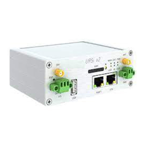
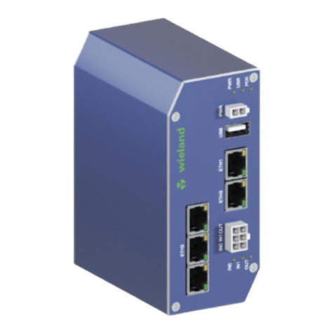
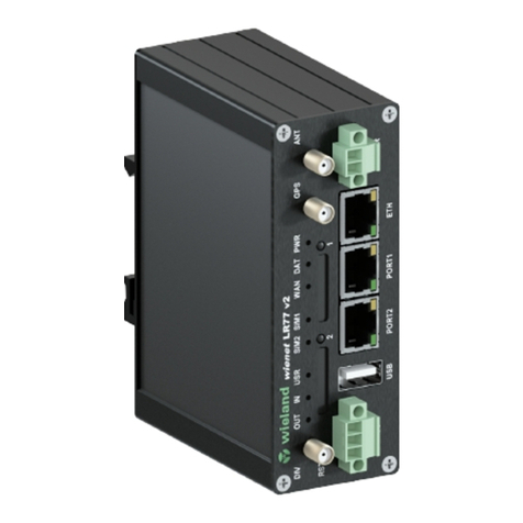
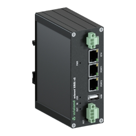
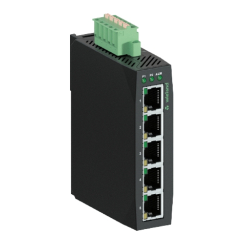
Wieland wienet router v2 User manual

wienet
Router v2
Expansion ports
User guide
Doc. no. BA000917
Last updated: 01/2019 (Rev. B)

2
Wieland Electric GmbH | BA000917 | 01/2019 (Rev. B)
This work is copyrighted material. The resulting rights remain with Wieland Electric Inc.
Any duplication of this document or parts thereof is permitted only within the limits of the
statutory provisions of the Copyright Act. Alteration or abridgement of this document with-
out the express written consent of Wieland Electric GmbH is prohibited.
wienet
is a trademark of Wieland Electric. Other names may in this assembly manual men-
tioned product and brand- trademarks or registered trademarks of their respective owners
could be used, whose use by third parties for their own purposes could violate the rights of
the owners.

Contents
Wieland Electric GmbH | BA000917 | 01/2019 (Rev. B)
3
Contents
1About this document ........................................................................... 5
1.1 Function of this document ............................................................................. 5
1.2 Scope and revision level ................................................................................ 5
1.3 Target group .................................................................................................. 5
1.4 Function and design of this installation manual ............................................. 5
1.5 Symbols and notations .................................................................................. 6
2Safety instructions ............................................................................... 7
2.1 Qualified persons ........................................................................................... 7
2.2 Intended Use ................................................................................................. 7
2.3 Expansion port safety .................................................................................... 8
3Product disposal instructions ............................................................... 9
4CNT ................................................................................................... 10
4.1 CNT description ........................................................................................... 10
4.2 Input and output description ........................................................................ 10
4.2.1 Analog input ................................................................................................ 10
4.2.2 Binary input ................................................................................................. 10
4.2.3 Counter input ............................................................................................... 10
4.2.4 Binary output ............................................................................................... 11
4.3 Selecting the current of binary output ......................................................... 11
4.4 Expansion port connection .......................................................................... 12
4.5 Description of protocol XC-CNT MODBUS ASCII Slave ............................... 13
4.6 Port status ................................................................................................... 18
4.7 Technical specifications ............................................................................... 18
4.8 Delivery identification .................................................................................. 19
5ETH .................................................................................................... 20
5.1 ETH description ........................................................................................... 20
5.2 Expansion port connection .......................................................................... 20
5.3 Port status ................................................................................................... 21
5.4 Technical specifications ............................................................................... 21
5.5 Delivery identification .................................................................................. 22
6MBUSD .............................................................................................. 23
6.1 MBUSD description ..................................................................................... 23
6.2 Expansion port connection .......................................................................... 23
6.3 Overload detection ....................................................................................... 24
6.4 Port status ................................................................................................... 24
6.5 Technical specifications ............................................................................... 25
6.6 Delivery identification .................................................................................. 25
7RS232 ................................................................................................ 26
7.1 RS232 description ........................................................................................ 26
7.2 Expansion port connection .......................................................................... 26
7.3 Port status ................................................................................................... 27
7.4 Technical specifications ............................................................................... 27
7.5 Delivery identification .................................................................................. 28

Contents
4
Wieland Electric GmbH | BA000917 | 01/2019 (Rev. B)
8RS485/RS422 ..................................................................................... 29
8.1 RS485/RS422 description ............................................................................ 29
8.2 Interface and power supply selection .......................................................... 29
8.3 Expansion port connection RS485 ............................................................... 30
8.4 Expansion port connection RS422 ............................................................... 31
8.5 Port status ................................................................................................... 32
8.6 Technical specifications ............................................................................... 33
8.7 Delivery identification .................................................................................. 33
9WiFi Module ....................................................................................... 34
9.1 WiFi module description .............................................................................. 34
9.2 Module configuration .................................................................................. 35
9.2.1 WiFi status ................................................................................................... 35
9.2.2 WiFi configuration ....................................................................................... 38
9.3 Port status ................................................................................................... 41
9.4 Technical specifications ............................................................................... 42
9.5 Delivery identification .................................................................................. 42
10 SD ...................................................................................................... 43
10.1 SD description ............................................................................................. 43
10.2 HUB ............................................................................................................. 43
10.3 SWITCH ....................................................................................................... 43
10.4 Compatibility with Wieland routers ............................................................. 44
10.5 Technical specifications ............................................................................... 44
10.6 State indication ............................................................................................ 44
10.7 Delivery identification .................................................................................. 44
11 Installation ......................................................................................... 45
11.1 Installing a router in a metal housing ........................................................... 45
12 Customer support .............................................................................. 47
13 Appendix ............................................................................................ 48
13.1 List of figures ............................................................................................... 48
13.2 List of tables ................................................................................................ 49

About this document
Wieland Electric GmbH | BA000917 | 01/2019 (Rev. B)
5
1About this document
Please read this chapter carefully before working with this users guide and the wienet mo-
bile router
1.1 Function of this document
This wienet router configuration guide describes the device and its functions. Use the Us-
er's Guide especially for the configuration of the mobile router.
1.2 Scope and revision level
This installation manual is valid for the products wienet VPN router, which are associated
with this configuration manual. The installation instructions accompanying the product are
downloadable in the electronic catalog of Wieland Electric. Be sure to always use the infor-
mation provided in the current version of this installation manual. The version and revision
level can be seen in the title page and the footer.
1.3 Target group
This manual is aimed at planners, engineers, installers and service personnel who are plan-
ning a remote control or remote maintenance solution and put into operation.
1.4 Function and design of this installation manual
This configuration guide instructs the technical staff of router installer on installation, pro-
gramming, operation and diagnosis of wienet router.
Chapter "Safety instructions" on page 7 contains basic safety measures. Please read and
follow these instructions in each case.
You can also use our Internet site at www.wieland-electric.com. You can also download
the following files:
•Product information wienet router and switches
•Data sheets wienet router
•Technical notes WIE-SERVICE24.com VPN Server portal
NOTICE

About this document
6
Wieland Electric GmbH | BA000917 | 01/2019 (Rev. B)
1.5 Symbols and notations
The symbol "DANGER" indicates imminent danger. If it is not avoided, it can result in
death or serious injury.
"DANGER" is used to warn of dangers at the time of the warning are already existing (eg
hot surfaces, sharp edges, pinch points, etc.).
It is used exclusively in danger of personal injury!
The symbol "WARNING" indicates a poetential threat. If it is not avoided, it can result in
death or serious injury.
The symbol "CAUTION" indicates a potential threat. If it is not avoided, slight or minor in-
jury can result.
Refer to notes for special features of a device.
Instructions also tell you about a potentially harmful situation. If it is not avoided, the sys-
tem or something in its environment can be damaged.
DANGER
WARNING
CAUTION
NOTICE

Safety instructions
Wieland Electric GmbH | BA000917 | 01/2019 (Rev. B)
7
2Safety instructions
This chapter is for your safety and the safety of equipment operators. Please read this
chapter carefully before working with a VPN-Router.
General Safety
•Personnel inalling, programming, operating or maintaining the wienet router must have
read and understood this manual.
•The personnel must be thoroughly familiar with all warnings, instructions and require-
ments contained in this manual.
•The applicable local safety, protection and installation requirements must be observed.
•The user is solely responsible for selecting the correct product and the technical design
in accordance with appropriate local regulations
ESD component
Observe precautions for handling electro sensitive devices!
2.1 Qualified persons
Wienet VPN router must be installed, configured, commissioned and maintained by quali-
fied persons only. Qualified persons are those who
•have appropriate technical training and
•have access to the wienet VPN router installation and configuration manuals, and have
read and understood them.
2.2 Intended Use
Please observe the following instructions:
•The router must be used in compliance with all applicable international and national laws
and in compliance with any special restrictions regulating the utilization of the router in
prescribed applications and environments.
•To prevent possible injury to health and damage to appliances and to ensure that all the
relevant provisions have been complied with, use only the original accessories. Unau-
thorised modifications or utilization of accessories that have not been approved may re-
sult in damage to the router and in a breach of applicable regulations. Unauthorized
modifications or utilization of accessories that have not been approved may result in the
termination of the validity of the guarantee.
•The router can not be opened.
•Caution! The SIM card could be swallowed by small children.
•Voltage at the feed connector of the router must not be exceeded.
•Do not expose the router to extreme ambient conditions. Protect the router against dust,
moisture and high temperature.
•The router should not be used at petrol stations. We remind the users of the duty to ob-
serve the restrictions concerning the utilization of radio devices at petrol stations, in
chemical plants, or in the course of blasting works in which explosives are used.
•Switch off the router when travelling by plane. Utilization of the router in a plane may en-
danger the operation of the plane or interfere with the mobile telephone network, and
may be unlawful. Failure to observe these instructions may result in the suspension or
cancellation of telephone services for the respective client, or it may result in legal sanc-
tions; it may also result in both eventualities.
•When using the router in the close proximity of personal medical devices, such as car-
diac pacemakers or hearing aids, you must proceed with heightened caution.
WARNING
CAUTION
CAUTION

Safety instructions
8
Wieland Electric GmbH | BA000917 | 01/2019 (Rev. B)
•If it is in the proximity of TV sets, radio receivers and personal computers, the telephone
may cause interference.
•It is recommended that you create an appropriate copy or backup of all the important
settings that are stored in the memory of the device
For any other use, or changes made to the equipment - even in the context of mounting
and installation - any warranty claim against Wieland Electric GmbH expires.
2.3 Expansion port safety
•The expansion port must be used in compliance with all applicable international and na-
tional laws and in compliance with any special restrictions regulating the utilization of
the communication module in prescribed applications and environments.
•Use only the original Wieland accessories. Thus you will prevent possible health risks
and damage to the devices and ensure compliance with all relevant provisions. Unau-
thorised adjustments or use of unapproved accessories may result in damage to the ex-
pansion port and breach of applicable laws. Use of unapproved adjustments or accesso-
ries may lead to cancellation of guarantee, which has no effects on your legal rights.
•Do not expose the expansion port to extreme conditions. Protect it from dust, moisture
and heat.

Product disposal instructions
Wieland Electric GmbH | BA000917 | 01/2019 (Rev. B)
9
3Product disposal instructions
The WEEE (Waste Electrical and Electronic Equipment) directive has been introduced to
ensure that electrical/electronic products are recycled using the best available recovery
techniques to minimize the impact on the environment. This product contains high quality
materials and components which can be recycled. At the end of its life this product MUST
NOT be mixed with other commercial waste for disposal. Check with the terms and condi-
tions of your supplier for disposal information.

CNT
10
Wieland Electric GmbH | BA000917 | 01/2019 (Rev. B)
4CNT
4.1 CNT description
The user interface CNT is for monitoring and processing analogue and binary signals and
for controlling (settings) of binary signals. There are 2 counter and 2 binary inputs or 4 bi-
nary inputs, 2 analogue inputs and 1 binary output available. The settings of binaries and
counter inputs by the help of firmware in which the single input and output is defined. Bi-
nary output is off by default configuration (is not switched to ground).
At expansion port CNT including in modem it is possible to use power supply manage-
ment. At permanent idleness the expansion port CNT is switch to low power supply mode
when demand current is very low (100 μA). Switch time to this status is program adjusta-
ble. The module wake up is possible by PORT status variation.
4.2 Input and output description
4.2.1 Analog input
On analogy input it detected current, converted to digital 12-bits value and modified by
multiplicative and additive constant. Next the value is averaged on user settings and stored
to PC memory. The basic range of input current is 0 – 20 mA at input resistance 100 Ohm.
Equal of value is:
((12b value + addit. constant) * multiplic. constant)/1000
The sample period on analogy inputs is adjustable in range 0 ÷ 65535 seconds. At value 0
it is sampling once per second and measurement circuit is permanent switch on. At sam-
pling it is possible to set time of measurement circuit switch from 16 ms to 375 ms.
On the basis of signal change about bigger value then setting upper/lower limit is gener-
ated alarm. The alarm end is on the basis of bigger/lower signal change about set hystere-
sis than is upper/lower limit.
4.2.2 Binary input
The binary input is potential-free contact which is 8x per second sampling and sampling
time is 1/64 seconds. For binary inputs it is possible to set active level to either log. 0 or
log. 1. Choosing active level can generate an alarm.
4.2.3 Counter input
The counter inputs are meters maximal to 100 Hz. The ratio impulses on input can be max-
imal 1:10, that means the impulse width must not be lower than 1/10 signal period. At
lower width the true evaluation of the metered signal is not guaranteed. For metering of
small frequencies (about mHz) it is important to set the multiplicative constant which mul-
tiplies metering frequency (flow) because of true evaluation.
On the basis of signal change about bigger value then setting frequency upper limit is gen-
erated alarm. Alarm is possible send after time after which upper limit must be overrun.
In case that it isn't any change on input, it is possible to define time after which the value
on input will zero.

CNT
Wieland Electric GmbH | BA000917 | 01/2019 (Rev. B)
11
4.2.4 Binary output
The binary output is realized by a transistor with open collector. In inactive state (log. 0)
the transistor no transfer and is as switch off. In active state (log. 1) is transistor switch on
and connect signal on ground (GND).
Maximal switching current on output is 100 mA. Maximal voltage which can be on transis-
tor collector is power supply voltage of the router.
The impulse length is possible set in range 125 ÷ 8000 ms which is possible to send on
output after impulses number setting (1 ÷ 65535) on input BIN1/CNT1.
In sleep mode the all input and output values are metered and controlled.
4.3 Selecting the current of binary output
If active level is set as log. 1, electric current can be selected with jumper. When jumper J4
(viz. picture) is mounted on pins, electric current value is 20 mA. When jumper J4 is not
mounted, electric value is 8 μA. If current value is 20 mA, CNT has higher consumption,
also it has higher resistance to industrial noise.
Figure 1: CNT board

CNT
12
Wieland Electric GmbH | BA000917 | 01/2019 (Rev. B)
4.4 Expansion port connection
Panel socket RJ45
Pin
no.
Signal mark Description Direction
1 BIN1/CNT1 Binary input/counter input Input
2 BIN2/CNT2 Binary input/counter input Input
3 BIN3 Binary input Input
4 BIN4 Binary input Input
5 GND Signal ground
6 OUT1 Binary output (open collector) Output
7 AN1 Analogue input Input
8 AN2 Analogue input Input
Typical connection of the router measuring circuits:
The router does not support modifying any signals of the CNT port, for example logical
functions.
Table 1: Connection of
CNT connector
Figure 2: CNT port
connector
Figure 3: Connection of
the router measuring
circuits
NOTICE

CNT
Wieland Electric GmbH | BA000917 | 01/2019 (Rev. B)
13
4.5 Description of protocol XC-CNT MODBUS ASCII Slave
The XC-CNT MODBUS ASCII slave protocol is a communication protocol by means of
which the router communicates with the CNT board. Using this protocol, the station con-
figures board software, reads the buffer, controls binary output and switches the main sta-
tion supply off.
The expansion port CNT communicates by this protocol with bit rate 9600 bit/s (8N1).
Address space
Address Access Description
0x0000 R/- Firmware type
0x0001 R/- Upper 16 bits of firmware version
0x0002 R/- Lower 16 bits of firmware version
0x0003 R/- Supports firmware characteristics
•bit 0 – analogy input AN1
•bit 1 – analogy input AN2
•bit 2 – counter input CNT1
•bit 3 – counter input CNT2
•bit 4 – binary input BIN1
•bit 5 – binary input BIN2
•bit 6 – binary input BIN3
•bit 7 – binary input BIN4
•bit 8 – binary output OUT
•bit 9 – automatic feeder control
•
bit 10 – fullduplex counter CNT1/CNT2
0x0004 R/- Maximal logs number in buffer
0x0005 R/W Marker of log launching and alarms work
0x0006 R/W Upper 16 bits of seconds number from 1.1.1970
0x0007 R/W Lower 16 bits of seconds number from 1.1.1970
0x0008 R/W Upper 16 bits of log actual number
0x0009 R/W Lower 16 bits of log actual number
0x000A R/- Alarms actual status
0x0100 R/- Binary inputs status
0x0200 Binary outputs status
0x0300 R/- Recalculate value of analogy input AN1 (with sign)
0x0400 R/- Recalculate value of analogy input AN2 (with sign)
Table 2: Address
space

CNT
14
Wieland Electric GmbH | BA000917 | 01/2019 (Rev. B)
Address Access Description
0x0500 R/W Upper 16 bits of counter CNT1 value
0x0501 R/W Lower 16 bits of counter CNT1 value
0x0502 R/- Prompt frequency CNT1
0x0503 R/- Average frequency CNT1
0x0504 R/- Minimal frequency CNT1
0x0505 R/- Maximal frequency CNT1
0x0601 R/W Upper 16 bits of counter CNT2 value
0x0601 R/W Lower 16 bits of counter CNT2 value
0x0602 R/- Prompt frequency CNT2
0x0603 R/- Average frequency CNT2
0x0604 R/- Minimal frequency CNT2
0x0605 R/- Maximal frequency CNT2
0x0F00 R/- 0x0000 always
0x0F01 R/- 0x0000 always
0x0F02 R/- Upper 16 bits of seconds number from 1.1.1970
0x0F03 R/- Lower 16 bits of seconds number from 1.1.1970
0x0F04 R/- Alarms status
•bit 0 – active level on input BIN1
•bit 1 – active level on input BIN2
•bit 2 – active level on input BIN3
•bit 3 – active level on input BIN4
•bit 4 – analogy input lower limit overrun AN1
•bit 5 – analogy input upper limit overrun AN1
•bit 6 – analogy input lower limit overrun AN2
•bit 7 – analogy input upper limit overrun AN2
•bit 8 – limit frequency overrun CNT1
•bit 9 – limit frequency overrun CNT2
0x0F05 R/- Binary inputs status
•bit 0 – level on input BIN1
•bit 1 – level on input BIN2
•bit 2 – level on input BIN3
•bit 3 – level on input BIN4
•bit 6 – level on output BOUT1
0x0F06 R/- Recalculate AN1 value (with sign)
0x0F07 R/- Recalculate AN2 value (with sign)
0x0F08 R/- Upper 16 bits CNT1
0x0F09 R/- Lower 16 bits CNT1

CNT
Wieland Electric GmbH | BA000917 | 01/2019 (Rev. B)
15
Address Access Description
0x0F0A R/- Prompt frequency CNT1
0x0F0B R/- Average frequency CNT1
0x0F0C R/- Minimal frequency CNT1
0x0F0D R/- Maximal frequency CNT1
0x0F0E R/- Upper 16 bits of counter CNT2 value
0x0F0F R/- Lower 16 bits of counter CNT2 value
0x0F10 R/- Prompt frequency CNT2
0x0F11 R/- Average frequency CNT2
0x0F12 R/- Minimal frequency CNT2
0x0F13 R/- Maximal frequency CNT2
0x1000 R/- 1. log – upper 16 bits of log number
0x1001 R/- 1. log – lower 16 bits of log number
0x1002 R/- 1. log – upper 16 bits of time stamps
0x1003 R/- 1. log – lower 16 bits of time stamps
0x1004 R/- 1. log – alarms status
0x1005 R/- 1. log – binary inputs status
0x1006 R/- 1. log– recalculate value AN1 (with sign)
0x1007 R/- 1. log – recalculate value AN2 (with sign)
0x1008 R/- 1. log – upper 16 bits CNT1
0x1009 R/- 1. log – lower 16 bits CNT1
0x100A R/- 1. log – prompt frequency CNT1
0x100B R/- 1. log – average frequency CNT1
0x100C R/- 1. log – minimal frequency CNT1
0x100D R/- 1. log – maximal frequency CNT1
0x100E R/- 1. log – upper 16 bits of counter CNT2 value
0x100F R/- 1. log – lower 16 bits of counter CNT2 value
0x1010 R/- 1. log – prompt frequency CNT2
0x1011 R/- 1. log – average frequency CNT2
0x1012 R/- 1. log – minimal frequency CNT2
0x1013 R/- 1. log – maximal frequency CNT2

CNT
16
Wieland Electric GmbH | BA000917 | 01/2019 (Rev. B)
Address Access Description
0x1100 R/- 2. log
0x1200 R/- 3. log
… R/- …
0xEF00 R/- 224. log
0xF000 -/W Samples stores period [min]
0xF001 -/W Allowed
•bit 0 – active level on input BIN1
•bit 1 – active level on input BIN2
•bit 2 – active level on input BIN3
•bit 3 – active level on input BIN4
•bit 4 – analogy input AN1 lower limit overrun
•bit 5 – analogy input AN1 upper limit overrun
•bit 6 – analogy input AN2 lower limit overrun
•bit 7 – analogy input AN2 upper limit overrun
•bit 8 – limit frequency CNT1 overrun
•
bit 9 – limit frequency CNT2 overrun
0xF100 -/W Binary inputs negative logical
•bit 0 – input BIN1
•bit 1 – input BIN2
•bit 2 – input BIN3
•
bit 3 – input BIN4
0xF200 -/W Binary outputs normal level
•Bit 0 – output OUT1
0xF201 -/W Feeder – impulse number on input BIN1/CNT1
0xF202 -/W Feeder – impulse length on output OUT1 [1/8 sec]
0xF300 -/W AN1 – samples period [sec]
0xF301 -/W AN1 – multiplicative constant (with sign)
0xF302 -/W AN1 – additive constant (with sign)
0xF303 -/W AN1 – hysteresis value (with sign)
0xF304 -/W AN1 – lower limit (with sign)
0xF305 -/W AN1 – upper limit (with sign)

CNT
Wieland Electric GmbH | BA000917 | 01/2019 (Rev. B)
17
Address Access Description
0xF306 -/W bits 7–3:
AN1 – metering circuit switch time
•0 → 1/64 sec
•1 → 2/64 sec
•…
•30 → 31/64 sec
bits 2–0:
AN1 – samples number for average
•0 → 1 sample
•1 → 2 samples
•2 → 4 samples
•4 → 8 samples
•5 → 16 samples
0xF400 -/W AN2 – samples period [sec]
0xF401 -/W AN2 – multiplicative constant (with sign)
0xF402 -/W AN2 – additive constant (with sign)
0xF403 -/W AN2 – hysteresis value (with sign)
0xF404 -/W AN2 – lower limit (with sign)
0xF405 -/W AN2 – upper limit (with sign)
0xF406 -/W bits 7–3:
AN2 – metering circuit switch time
•0 → 1/64 sec
•1 → 2/64 sec
•…
•30 → 31/64 sec
bits 2–0:
AN2 – samples number for average
•0 → 1 sample
•1 → 2 samples
•2 → 4 samples
•4 → 8 samples
•5 → 16 samples
0xF500 -/W CNT1 – multiplicative constant
0xF501 -/W CNT1 – upper limit
0xF502 -/W CNT1 – time of limit overrun [sec]
0xF503 -/W CNT1 – time for metering reset [sec]

CNT
18
Wieland Electric GmbH | BA000917 | 01/2019 (Rev. B)
Address Access Description
0xF600 -/W CNT2 – multiplicative constant
0xF601 -/W CNT2 – upper limit
0xF602 -/W CNT2 – time of limit overrun [sec]
0xF603 -/W CNT2 – time for metering reset [sec]
0xFFFF -/W Switch main supply off on set time [min]
4.6 Port status
LED port indicator
Green LED
Indicates binary input 0
Yellow LED
Indicates binary input 1
Status indication is supported from 5th revision of boards.
4.7 Technical specifications
Expansion port CNT
Power supply
Internal
3.3 V
Sleep 100
μ
A (counter is
functional)
Operation
2 mA
Environment
Operating temperature
-30 … +60 °C
Storage temperature -30 … +85 °C
Standards
Emission
EN 55022/B
Immunity ETS 300 342
Safety
EN 60950
Isolation
EN 60747
Inputs/Outputs 2x counter Max. 100 Hz, ratio
max. 1:10
2x analogue inputs 0 … 20 mA,
Rin 100 Ohms
2x binary inputs Reed contact with J4 -
20mA without J4 8μA
1x output (open collector) 30 V / 100 mA
Others Voltage resistance Permanent
Sleeping mode Controlled
Table 3: CNT status in-
dication
NOTICE
Table 4: CNT technical
specifications

CNT
Wieland Electric GmbH | BA000917 | 01/2019 (Rev. B)
19
4.8 Delivery identification
Trade name Type name Power supply
XC-CNT
XC-CNT
Internal or external supply
Table 5: CNT delivery
identification
Figure 4: Example of
expansion port CNT la-
bel

ETH
20
Wieland Electric GmbH | BA000917 | 01/2019 (Rev. B)
5ETH
5.1 ETH description
The expansion port ETH is created as expansion port which enables to use of the next
hardware interface of Wieland modems for next signal processing. This interface is physi-
cal connected on RJ45 connector on appropriate modem. The expansion port ETH is inter-
nal supplies from appropriate modem. Against bus overload the expansion port ETH is pro-
tect.
Expansion port ETH is possible fitted only into PORT1.
5.2 Expansion port connection
Panel socket RJ45.
Pin no.
Signal mark
Description
Direction
1 TXD+ Transmit data - positive pole Input/Output
2 TXD- Transmit data - negative pole Input/Output
3 RXD+ Receive data - positive pole Input/Output
4 — —
5 — —
6 RXD- Receive data - negative pole Input/Output
7 — —
8 — —
Port ETH is not POE (Power Over Ethernet) compatible.
NOTICE
Table 6: Connection of
the ETH connector
Figure 5: ETH port con-
nector
NOTICE
Other manuals for wienet router v2
1
Table of contents
Other Wieland Network Router manuals

Wieland
Wieland 83.041.0050.1 User manual

Wieland
Wieland Wienet UR5i User manual

Wieland
Wieland wienetUMS 8-4POE-W User manual

Wieland
Wieland wienet WR-LTE v3 SL User manual

Wieland
Wieland 83.041.0665.3 User manual

Wieland
Wieland wienet UMS 5-L User manual

Wieland
Wieland xr5i v2 User manual

Wieland
Wieland wienet LMS 16-W User manual

Wieland
Wieland LAN ER300 GLOBAL User manual

Wieland
Wieland wienet UMS 20-16G-4SFP-W User manual