City-Netek CN-1108 Operating and safety instructions

CN-1108
8-Ports 1 Mbps HomePNA+1-Port 10/100
Base-TX Ethernet Switch
Setup and Installation Manual
Version 2.0

CN-1108 Setup and Installation Manual
1
PREFACE 2
1. INTRODUCTION 3
2. CN-1108 TECHNICAL SPECIFICATIONS 4
3. HARDWARE DESCRIPTION & PACKAGE CONTENTS 5
4. EQUIPMENT MOUNTING SETUP 6
4.1 RACK MOUNT 6
4.2 SIMPLE STACK UP 6
4.3 STACK MOUNTING 6
4.4 CABLE SELECTION 6
5. LED INDICATORS 7
6. CN-1108 CONNECTION 8
7. CONSOLE PORT SETUP 9
8. ICD COMMAND INDEX 10
9. SETTING VLAN FUNCTIONALITY 11
10. AUTO NOISE LEVEL FEATURE 12
11. HIGH/LOW POWER MODE 14
12. FREQUENTLY ASKED QUESTIONS (FAQ) 15
12.1 HPNA 15
12.2 SWITCH 15
12.3 LAN 17
12.4 WAN 18
12.5 PBX 18
13. TROUBLESHOOTING 19
14. CN-1108 FACTORY DEFAULT 21
CONTACT INFORMATION 22

CN-1108 Setup and Installation Manual
2
PREFACE
This guide has been constructed in a simple to follow and navigate style, meant for
VAR, SI, and reseller installation situations.
Keep this guide in a safe place; it contains useful commands required for the setup
of the switches core functions in the event of a power loss or other interruption.
Information printed within this guide is subject to change at any time without notice.
All specifications and parameters, including commands are subject to change without
notice.
Some information in this guide is acquired from the World Wide Web.
All photographs, text, and diagrams within this publication are the sole property of
City-Netek Inc., and may not be reproduced at anytime, without the written consent of
City-Netek Inc.

CN-1108 Setup and Installation Manual
3
1. INTRODUCTION
Thank you for choosing the CN-1108 HPNA Switch for your MDU Solution.
City-Net has been on the forefront of HPNA technology since its inception, and will
always strive to create quality, cost-effective solutions for HomePNA installers and users.
Conventional office Ethernet LAN installation has become more complicated,
expensive and time consuming. By choosing the CN-1108 HPNA Switch, you have
enabled your network to have Ethernet and HPNA accesses. The CN-1108 an Ethernet
port, to offer you network connection, as well as 8 VLAN HPNA ports ready to plug into
your existing wiring system using current Cat. 3/RJ-11 installations.
Some highlights of the CN-1108 include:
•Supports security with port based VLAN function
•Auto Noise Leveling (Automatic & Manual)
•Eight 1Mbps HPNA Ports
•One 10/100 Mbps Base-TX Ethernet Ports
•One Console Port for CN-1108 unit
•Easy installation – no new wire required inside the building
•Easy to use menu system and command interface
•HomePNA and Ethernet ports statuses monitoring
•Frequency division multiplexing for uninterrupted simultaneous voice/data
transmission
•Layer 2 Switching
•Supports full and half duplex modes
•Store-and-Forward mechanism
•HPNA port transmission speed up to 1Mbps
•Back pressure and IEEE 802.3X compliant flow control
•Supports 8K MAC addresses entries
•Standard 19” Rack-mountable
•Less distance restriction (500 ft or 160 m) than regular Ethernet (100 m)

CN-1108 Setup and Installation Manual
4
2. CN-1108 TECHNICAL SPECIFICATIONS
zEight (8) HPNA Ports
HPNA Specs 1.1
1Mbps Speed
Transmit Distance: 500 ft full throughput, 1000 ft factory tested
LED: Link, Activity, Collision
RJ-11 port type for use with twisted pair cable
zOne (1) Ethernet Port
10/100 Base-TX, Auto-negotiation
IEEE 802.3, 802.3u
LED: Link/Activity, 10/100, Full Duplex/Collision
zOne (1) Console Port
Baud Rate: 19200 bps, 8 Data Bits, 1 Stop Bit, No Parity, No Flow Control
Console Management Command (Local Mode)
zPhysical Specifications:
AC Input: 100 - 250 VAC, 47-63 Hz, Internal Universal Power Supply
Power Consumption: 12W Max
Operating Temp: 0 - 50°C
Storage Temp: -25 - 70°C
Humidity: 10% - 90% Non-Condensing
Certification: FCC, CE, VCCI, JATE Safety Compliance & Emissions, BSMI
Weight (Net): 1.75 kg
Dimensions: 300 mm × 210 mm × 44 mm

CN-1108 Setup and Installation Manual
5
3. HARDWARE DESCRIPTION & PACKAGE CONTENTS
Upon opening your package you should have the following items:
•(1) Power Cord w/Ground
•(1) CN-1108 HomePNA Switch Hub
•(1) Setup and Installation Manual
•(1) Mounting Brackets (Rack Install)
•(4) Screws For Shelf or Rack Install
If any of these items are missing, please contact your vendor immediately before
continuing. For additional manuals or mounting feet please contact your vendor.
Before removing the switch unit from the package please be sure to remove all static
devices and static electricity from your body by touching an available metal plate or
grounding point.
Your new CN-1108 has eight RJ-11 HomePNA Ports, one Ethernet Port, and one Console
Module.

CN-1108 Setup and Installation Manual
6
4. EQUIPMENT MOUNTING SETUP
4.1 RACK MOUNT
The CN-1108 is supplied with mounting ears for easy installation into a Standard
19” rack configuration cabinet. Simply use the supplied ears and screws to mount it to
your current rack.
1. Use the included screws to secure ears into the sides of the CN-1108 in the
provided pre-drilled holes.
2. Align the unit into a single 19” rack space and secure using standard rack
mount screws, the use of a nut is optional.
4.2 SIMPLE STACK UP
When mounting the CN-1108 on a shelf, be sure to install the included rubber feet
onto the bottom of the unit to prevent scratching of the mounting surface, as well as to
allow clearance between the switch and surface for better airflow. Once feet are installed
onto the switch unit, allow for a clearance of at least 5 inches from rear to wall, and 1-2
inches on each side, for adequate airflow.
4.3 STACK MOUNTING
Use the diamond shaped stackable mounts to attach to CN units together from the
sides. Simply apply the diamonds to each side using the included screws to the upper
holes on the bottom device, and the lower holes on the top device.
4.4 CABLE SELECTION
Selecting the correct cable type(s) and length(s) will assist you in making a clean
and error free installation. For Ethernet uplinks and connections use Cat. 5 or higher
certified cables, to minimize cross talk and noise in the cable. For easier connection and
safer operation use booted RJ-45 connections as well. For HPNA ports, use of shielded
Cat. 5 are highly recommended. Refrain from using excess cable when installing to
further reduce line noise and cross talk.

CN-1108 Setup and Installation Manual
7
5. LED INDICATORS
EIA 232
CN-1108
XTLK
VLAN
SNMP
ALARM RESET
0
1
2
3
ID
POWER
LNK/ACT
100/10
FDX/COL
NORMAL
UPLI NK
5678
LNK
ACT
COL
12 3 4
LNK
ACT
COL
ALARM
SNMP
VLAN XTLK
POWER
LNK/ACT
100/10
FDX/COL
LNK
COL
ACT
Module
LEDs Function Color Status Description
SNMP SNMP Mode Green -- Reserved
On Auto Noise Level function is on
XTLK Auto noise level
status Green Off Auto Noise Level function is off
On VLAN is on
VLAN Virtual LAN status Green Off VLAN is off
Alarm -- -- -- Reserved
ID 0,1,2,3 -- -- -- Reserved
LEDs Function Color Status Description
On Power on
Power Power Indication Green
Off Power off
Ethernet Port
On The Ethernet port is linked
Blinking The Ethernet port is sending or
receiving data
LNK/ACT Ethernet Port Active Green
Off Port is not connected
On The speed is at 100Mbps
10/100
Ethernet port
Transmit And
Receive Speed
Green
Off The speed is at 10Mbps
On Port is operating at full duplex
Blinking Transmission collisions have
occurred on the Ethernet port
FDX/COL
Full Duplex
Transmission And
Collision Indicator
Yellow
Off Port is operating at half- duplex
HomePNA Port
On The HomePNA port is linked
LINK Link Indication Green
Off The HomePNA port is not linked
On The HomePNA port is sending
and receiving data
Blinking The HomePNA port is linked but
not active
ACT Activity Indication Green
Off The HomePNA port is not linked
COL Collision Indication Yellow Blinking
Transmission Collision has
occurred on the HomePNA port

CN-1108 Setup and Installation Manual
8
6. CN-1108 CONNECTION
This illustration shows the CN-1108 and a description of its ports.
Workstation Workstation Workstation
EIA 232
CN-1108
XTLK
VLAN
SNMP
ALARM RESET
0
1
2
3
ID
POWER
LNK/ACT
100/10
FDX/COL
NORMAL
UPLINK
5678
LNK
ACT
COL
12 3 4
LNK
ACT
COL
Server
Cat. 5 Cable
Workstation Workstation
Figure 1

CN-1108 Setup and Installation Manual
9
7. CONSOLE PORT SETUP
This portion of the manual will discuss connection to the switches core functions
via the Console Port. For connection to the CN-1108 via the console port, you must use
DB-9 to Serial DB-9 cable (not included). Connect the Console port on the unit to PC
COM port using the DB-9 to Serial DB-9 cable. These cables have custom pin out
assignments, and the use of other cables or converters may cause damage or malfunction
to the equipment.
Once you have connected the module to your console port, start any terminal
program, such as HyperTerminal by Hilgraeve® Software in Windows® 98. Once you
have started your terminal application, you will need to set the terminal with the
following settings:
Also note that this switch can be used with a dumb terminal that has a DB-9 serial
type port installed. If using a dumb terminal, set the dip switches on the terminal to the
appropriate settings as listed above.
Now that you are logged into the switch, proceed to the next section for an
explanation of ICD commands.
Baud Rate Data Bits Parity Stop Bits Flow Control
19200bps 8 None 1 None

CN-1108 Setup and Installation Manual
10
8. ICD COMMAND INDEX
ICD Console Command & Description
ICD COMMAND COMMAND DESCRIPTION
RRead All Am79C901s register (console)
RR## Read All Port Reg.##
RP## Read Port ## All Reg.
WP##R##Hxxxx Write Port## Reg.## with hex xxxx
AO Enable Auto Noise Level on all ports (Please refer to Auto
Noise Level Functionality section)
AF Disable Auto Noise Level on all (Please refer to Auto
Noise Level Functionality section)
A Display Auto Noise Level Status
VF VLAN Off
VO VLAN On
V Display VLAN Status
P Display Status of All Ports
PD## Disable given port (only for HPAN Port)
PE## Enable given port (only for HPNA Port)
C Clear Packet Counters of All Port Counter or Given Port
PC## Display Transmit/Receive/Collision Counters in Hex of
given port or all ports when port number is not enter
U Display Unit Information
S Save Data
RS Reset Unit
RSW Restore MIB Agent Factory Defaults and Reset Switch
X To Exit ICD Command Mode
Note: For the VLAN and save commands, CN-1108 takes approximately 52 seconds to
check the integrity of all the registers.
Symbol Key:
## - HPNA Port number or Register number
rr - Am79c901s Register Number
xxxx - Hexadecimal Data

CN-1108 Setup and Installation Manual
11
9. SETTING VLAN FUNCTIONALITY
The VLAN function offers security and flexibility of controlling each port access to
one another. This feature is useful in MDU and hotel situations where you would not
want each computer to be able to “see” all other computers connected to the switch.
However, in some situation you may need to have a few ports with the capability of
communicating with one another. Such situations may arise for sharing of files,
collaboration software, faster multi-player gaming, etc.
Activating the VLAN function allows each port to be individualized, and
non-communicative to the other ports on the switch in regards to local traffic.
Deactivating VLAN allows the switch to act as a normal Ethernet/HPNA Switch by
passing along multicast and broadcast traffic to each port. Disabling this feature would be
useful when installing the switch in an office setting and file sharing/print sharing.
Through ICD command interface you can turn the VLAN function on or off. In
ICD interface simply type “VO” to activate VLAN function, and “VF” to deactivate the
VLAN function.
CN-1108 Setup and Installation Manual
12
10. AUTO NOISE LEVEL FUNCTIONALITY
Auto Noise Level Adjustment is a very useful feature in CN-1108 when installing
under noisy line or old wiring conditions. The unit can automatically compensate for
noise within the line by analyzing the signals of each port and adjust its noise floor
accordingly.
You can turn on/off the Auto Noise Level feature through the ICD command
interface via Console or Telnet. The commands to activate and deactivate this feature
within the ICD command interface are “AO” and “AF” respectively.
Occasionally you will find that the Auto Noise Level feature unable to compensate
for the noise in certain lines. This phenomenon is usually caused by surrounding noise
lines or bad wirings (high impedance). Signs of trouble with the noise floor would
indicate by excessive collisions on the affected port, or loss of link status with a sudden
gain in status.
Noise level threshold can be adjusted manually through console by changing the
register value; Register 25 is to record the setting of noise level, while register 23 is to
write/change the value of noise level.
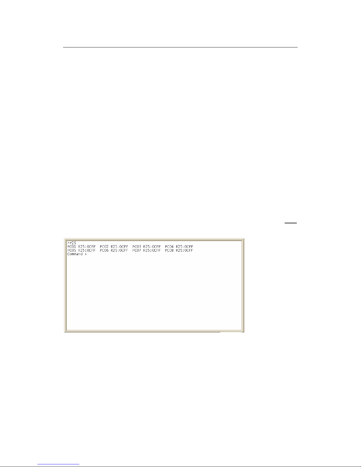
Through Register 25 we may monitor the signal peak and noise level. Type rr25
in the command line for Register 25 values:
FigureA
PC01 indicates port 1, PC02 indicates port 2, PC03 indicates port 3, etc. R25: indicates
register.25, for 0CFF; the first two digits (0C) indicates the noise level, which is the
default value of CN-1108. The second two digits FF indicates the peak signal level,
usually range from 30 to 60 hex (4A to 58 as shows). FF indicates no connection of that
port.

CN-1108 Setup and Installation Manual
13
If the telephone wire condition is clean (no bundled wires) the noise level will be
less than 3 and the peak level of the normal signal is about 50 hexes. But in strong
cross-talk environments the noise level is sometimes as high as 10 to 15, in this case the
noise floor (Register 23, the Noise Control Register) will be set to 1A to avoid cross talk
noise.
But in some reflection signal (noise) case, the normal signal has been cancelled by
the reflection signal original from the real signal. So the peak signal may be only 8 to 10.
So the Noise floor has to be set to about 5.
For example: Please refer to Figure A; port 1 value is PC01R23:0CFF, the noise
level is 0C, to change this value form 0C to 0A, using the following command:
WP01R23H0AFF. Please save the new value with the “S” command after finished
issuing commands.

CN-1108 Setup and Installation Manual
14
11. HIGH/LOW POWER MODE
The CN-1108 contains two power modes for transmission: Low power, and
High power. This setting was integrated within the switch for installations that contain
some long distance HPNA port installations of 500 ft and 1000 ft. Power modes are
adjustable on a per port basis, but with the following side effects:
I. High Power Mode will cause much more Cross Talk within the line of the port
modified.
II. Data Rate may be slightly affected by raising the power mode, resulting in slower
transmission.
To adjust to high power mode use the following command: WP##R16H0505.
This will change the value of register 16 from 0005 hex (default) to 0505 hex. By
reading back the register 17, the value should be 0364 hex instead of 0324 hex as the low
power low speed mode. Please save the new value with the “S” command after finished
issuing commands.

CN-1108 Setup and Installation Manual
15
12. FREQUENTLY ASKED QUESTIONS (FAQ)
12.1 HPNA
Q: What does HPNA stand for?
A: HPNA Stands for Home Phoneline Networking Alliance
Q: With HPNA, Can I use my phone or fax and my Internet at the same
time?
A: Yes, you can use them at the same time.
12.2 SWITCH
Q: How many users can log into the switch through telnet at once?
A: Telnet and Console only accept only 1 connection at a time, and
Telnet and Console cannot be access at the same time.
Q: Can I turn off ports individually?
A: Yes, Use the Console or Http Interface to do so.
Q: Can I adjust bandwidth per port?
A: No, you cannot change the throughput thresholds.
Q: Will the switch ever get “too busy” to handle large volumes of data?
A: No, with the flow control mechanisms and Back Pressure features in
place, the unit will always be able to operate at maximum
throughput.

CN-1108 Setup and Installation Manual
16
Q: If I turn off my CN-1108, will the settings be saved?
A: YES, as long as you used the “S” save command in the ICD
command interface, all-manual changes will be saved in the event
that you turn off, or lose power to your switch.
Q: Can I use one port to support multiple users?
A: Yes, the HPNA standard supports up to 25 subscribers per port, for
shared 1Mbps access on that port, however VLAN functionality is
based per port on the switch itself. If multiple users are connected to
the same port, then they will be able to communicate with each other
regardless of the VLAN setting on the switch.
Q: I am using my CN-1108 for my office network; I cannot see the
file-sharing computer. Is there something wrong with my switch?
A: Not at all, just set the VLAN function to OFF, and all ports will be
able to communicate with one another.
Q: Is the 1Mb of speed per port, or for the whole backplane?
A: The ports are capable of 1Mb full duplex max throughput per port;
the back plane can handle vast amounts of traffic.
Q: Is the switch firmware upgradeable?
A: Yes, at minimum cost. Please contact your vendor for updates.
Q: Are there serviceable parts inside?
A: No, you should not open the case at anytime, due to risk of shock and
void of warranty.
Q: Should the FDX/COL light stay on all the time on my Ethernet ports?
A: Yes, if you have full duplex Ethernet running, the light will be always
on. Collisions are only present when the light flashes.

CN-1108 Setup and Installation Manual
17
12.3 LAN
Q: Can I connect computers using HPNA at distances longer than
1000ft?
A: Under certain conditions it may be possible, our tests have proved
1000ft. as acceptable.
Q: How many pairs (cable pairs) does HPNA transmission require?
A: One pair.
Q: Which pair runs the data in a 2 pair RJ-11?
A: It will run on either pair, just be sure that both ends of the cable have
the same wiring configuration.
Q: Can I use Cat 5 Cable to make 4 RJ-11 connections?
A: Yes.
Q: Will other types of HPNA CPE (Customer Premises Equipment)
work with the CN-1108?
A: Yes, however all Manufacturers do not guarantee the performance of
their products when used with other manufacturer products.

CN-1108 Setup and Installation Manual
18
12.4 WAN
Q: What types of WAN connections are compatible with the CN-1108?
A: Virtually any connection that has an Ethernet interface can be used.
Q: What router should I use for best results?
A: Any router should perform well with the HPNA switch.
Q: My router has a firewall, how do I get through remotely to my switch
to monitor and change settings?
A: In your firewall you should have a private connection-tunneling
feature, to allow direct connections between addresses on your
network and out of band workstations. Refer to your Router User
Manual.
12.5 PBX
Q: Will the switch work with all PBXs?
A: Yes, your CN-1108 will work with all analog PBXs and most Digital
systems, however not all PBX is compatible with this product, you
may require a low pass filter, contact your vendor for availability.

CN-1108 Setup and Installation Manual
19
13. TROUBLESHOOTING
This section covers some common problem areas, also known fixes and
solutions. Although the solutions offered in this section should solve your
problem, occasionally a problem might arise that takes on a symptom of an issue,
hence cannot be solved in the same fashion. If you are unable to fix the problem
after going through this section, contact your vendor technical support for
assistance.
Cross Talk Noise: Can Include Collisions and Link On/Off
Cross Talk Noise can be generated by HomePNA signals of bundled pairs
of telephone wire. When two pairs are adjacent to each other, or twisted around
each other they can create cross talk noise. A significant amount of cross talk
noise can be generated on the HPNA switch due to the high power output of the
switch. Therefore, when telephone pairs are close together and twisted at the
switch, the adjacent port may suffer from above problem.
Available solutions for this issue are:
1. Use Cat. 5 certified cables between the MDF and switches,
including Cat. 5 punchdown blocks and shielded/booted RJ-11
connectors going into the switch.
2. Turn on the Auto Noise Leveling Feature
3. Make manual adjustments if previous solutions failed. Manual
adjustments are covered in the “Auto Noise Level Feature”
chapter.
Reflection Noise: Caused by Un-Terminated Phone Jacks
HPNA uses Frequency Division Multiplexing to allow simultaneous flow
of data and voice services on same pair of wires. For this reason, your phone
lines also act as data transmission lines for the frequency range of 5.5 MHz to 9.5
MHz. Therefore, if there is any open jack at the end of the circuit in HPNA port,
the frequency information (data) will have nowhere to go, and reflect back into
the system, causing noise and non-function.
Solution:
Terminate those jacks using a CN-Terminator or one of its specifications.
Otherwise, remove the excess jacks from the circuit.
Table of contents
Other City-Netek Network Router manuals


