WifiTrax Model Science WFD-46 User manual

WifiTrax Model Science www.wifitrax.com WifiTrax Model Science www.wifitrax.com
Factory Reset
You can factory reset the module by pressing and holding down the
Factory Reset button until the Green LED flashes. The module will then
reset.
Getting More out of your WFD-46
Access the WFD-46 Manual at http://www.wifitrax.com/manuals/WFD-
46/WFD-46-Manual.pdf
More Information
Other resources:
http://www.wifitrax.com/appNotes/howToArticles.html
WifiTrax products are made in Australia using globally-sourced components and
services. Check our website for warranty information.
This product is not a toy. Keep away from children. It is not suitable for use by persons
under 14 years of age.
Warning: This product contains chemicals known to the state of California to cause
cancer, birth defects or other reproductive harm.
WifiTrax www.wifitrax.com
WFD-46 Getting Started Guide
This document is online at http://www.wifitrax.com/appNotes/quickStart/WFD-
46-Quick-Start.pdf. Please consult the full WFD-46 manual for much more detail
at http://www.wifitrax.com/manuals/WFD-46/WFD-46-Manual.pdf
Package Contents
1 x WFD-46 Module in Static Shielding Bag, this document, mounting Kit
WFD-46 5 Amp Wi-Fi/DCC Trackside
Adjustable Booster with Auto-Reverse
Bipolar DCC
Track
Output
Bipolar
Track DCC
Input
Alternative
Power
18V-24V
Power
18V-24V
Control Bus
Input/Output
Control Bus
Input/Output
Red Power LED
Green Net LED
Blue DCC Normal LED
Yellow DCC Reversed LED
Factory Reset
(Press and hold until green LED flashes)
Firmware
Update
DIP Switches ON
OFF
1234
DCC Voltage Adjust
Clockwise to Increase
Figure 1. WFD-46 Connections
WifiTrax Model Science www.wifitrax.com WifiTrax Model Science www.wifitrax.com
What does WFD-46 Wi-Fi/DCC Trackside
Command Station/Booster do?
The WFD-46 Wi-Fi/DCC Booster is a 5 Amp/3 Amp DCC Booster that
receives a DCC signal from a DCC Command Station and delivers DCC
Track Power to a Power District consisting of a section of track isolated
by a gap in both rails. Here is a summary of its features:
•5 Amp continuous capability
•Variable DCC Output Voltage approx. 9.8 –20 Volts peak-to-
peak in two ranges
•3 Amp or 5 Amp Overcurrent Protection
•Input from Track DCC or DCC Control Bus
•Auto-reversing for return loops, wye etc.
•Wi-Fi Monitoring of Status and approximate current load
LED Indicators
Red LED: Lights as soon as power is applied to the module.
Blue LED: Lights when the module receives a valid DCC input and is
supplying DCC to its track outputs. Flashes slowly if there is insufficient
Power Supply voltage to provide the desired output voltage. Flashes
quickly when an over-current or short condition is detected.
Amber LED: Lights instead of the blue when the Track Output is
reversed.
Green LED: Flashes when Wi-Fi traffic occurs. Lights continuously when
module is connected to a home network router.
Getting Started
If this is your first purchase of a WFD-46, you have various options to
connect it to your layout:
•Connect the control bus of your existing DCC Command Station to
the WFD-46 as in Figure 2, or
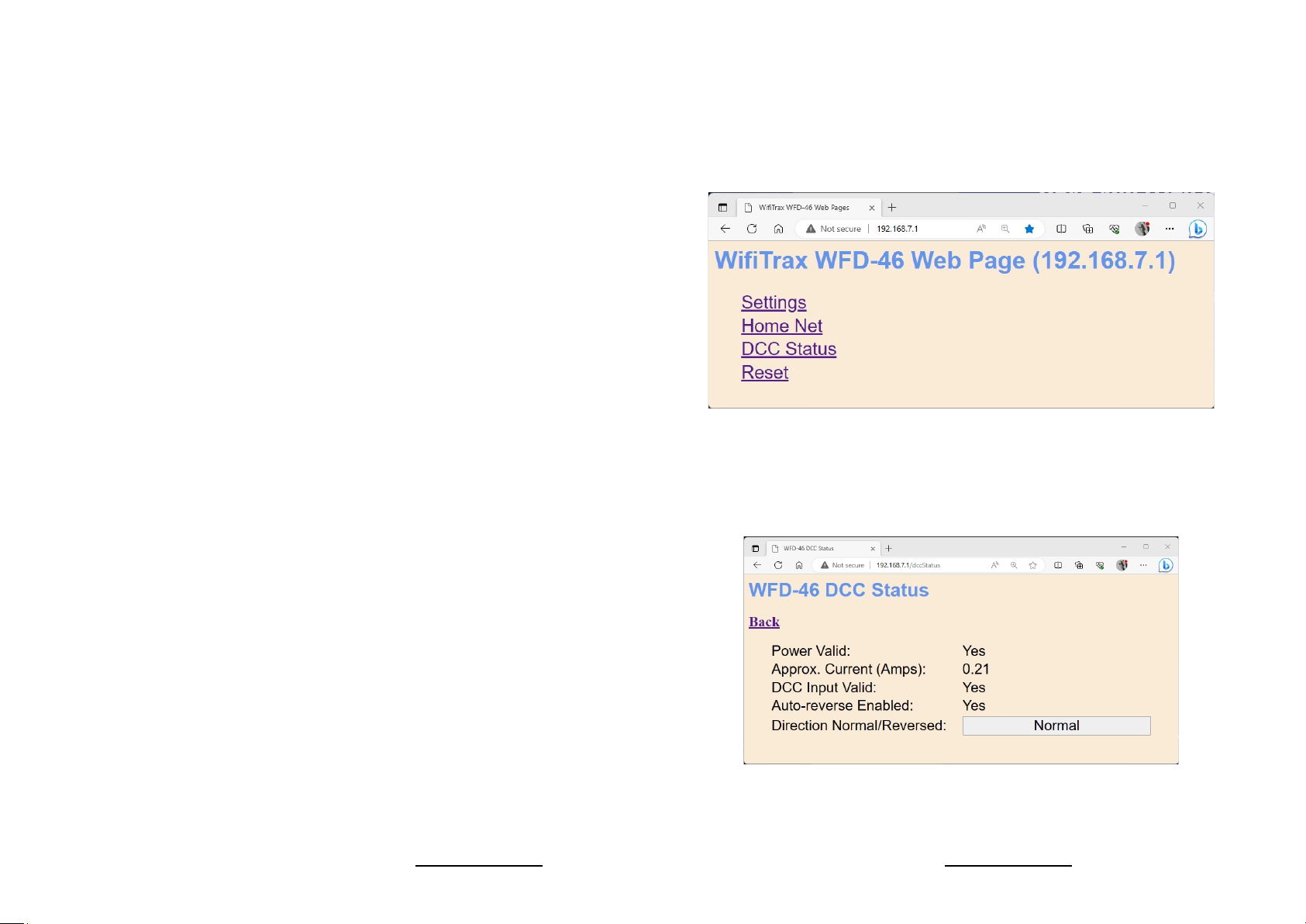
(4) Once your device has connected to the WFD-46 Wi-Fi, open a
browser such as Google Chrome and type the IP Address of the
module:
192.168.7.1
(5) The main menu is displayed as below.
Click on any of the menu items to make changes to the configuration of
the WFD-46 module. The details of the Settings and other pages are
described in the WFD-46 Manual.
As an example, the DCC Status page is shown below:

WifiTrax Model Science www.wifitrax.com WifiTrax Model Science www.wifitrax.com
Using The Wi-Fi Features of WFD-46
The WFD-46 displays a web page containing a menu of features. This
web site is internally generated and does not need a connection to the
internet.
To connect to the WFD-46 web page using Android follow these steps:
(1) Press the Home button and tap the settings icon on your Android
phone or tablet:
(2) Find the Wi-Fi option. On Android 7, you tap Connections on the left,
then Wi-Fi on the right.
(3) You see a list of available Wi-Fi Connections on the right. Look for
one like wftrx_WFD46_1_XXXXXXXX_7, where XXXXXXXX is the serial
number of your unit that appears on its label. Tap on that –no
password is required –and wait for it to connect.
•Use the track DCC (bipolar DCC) output from your existing command
station/booster to your WFD-46 as in Figure 3. You then connect its
track outputs to a new DCC Power District.
Power District 1
WFD-46
DCC Control
Bus
18-24 Volt DC
Power Adapter
Bipolar
Track
Dcc
Power Adapter Cable
Command Station
e.g. NCE SB5
Control Bus Output
Figure 2 Connecting a WFD-46 to a Command Station. You can use any command station
Power District 2
WFD-46
18 or 24
Volt DC
Power
Adapter
Bipolar DCC
to Track
Power Adapter Cable
Power District 1 Gap in
Both
Tracks
Command Station
e.g. NCE Power Pro
System
Track DCC
Output
Bipolar DCC
to Track
Bipolar DCC Input to WFD-46
Figure 3 Connecting a WFD-46 to a WFD-27 Wi-Fi Command Station/Booster. You can use
the output of any booster.

WifiTrax Model Science www.wifitrax.com WifiTrax Model Science www.wifitrax.com
Switch
Function
Setting
Remarks
1
Output Voltage
Range
On
Range 1: 9.5 to 15 V
Output. 18 Volts DC
Input Required.
1
Output Voltage
Range
Off
Range 2: 12 to 20 Volts
Output. 24 Volt Input
Required.
2
Overcurrent
Shutdown
On
3 Amp Shutdown
2
Overcurrent
Shutdown
Off
6 Amp Shutdown
3
DCC Input
Source
On
Control Bus Input
3
DCC Input
Source
Off
Bipolar Track DCC Input
4
Auto Reverse
Enable
On
Auto Reverse Disabled
4
Auto Reverse
Enable
Off
Auto Reverse Enabled
Table 1 WFD-46 DIP Switch Settings for Simple Single Power District Operation
Installation Instructions
(1) Connect your WFD-46 according to either Figure 2 or Figure 3. You
can use Wifitrax or any manufacturer’s compatible product to
provide DCC as you wish. Just remember to distinguish between
Control Bus inputs and Bipolar Track DCC inputs.
(2) Set the DIP switches on your WFD-46 according to your requirements
as in Table 1.
•If you want to use range 1, supply 18 volts DC. If you want to use
Range 2, supply 24V DC. Do not exceed the maximum DCC
voltage for the decoders on your layout. 14V DCC Peak to Peak is
the normal standard for HO.
•Set the Over-Current Shutdown to 3 Amp or 6 Amp.
•Select the DCC Input Source to Control Bus or Bipolar Track DCC
according to whether you are wired as in Figure 2 or Figure 3.
•Select either Auto-Reverse Enable or Disable. If you disable
Auto-Reverse you need to make sure any existing Power Districts are
wired with the same polarity as the WFD-46. Do not enable Auto-
Reverse in two adjacent Power Districts supplied by WFD-46 or they
will both try to reverse and defeat each other.
(3) Connect a suitable Power Adapter to your WFD-46. If you are using
Output Voltage Range 1 (9.5 to 15V) 18V is recommended. You can
use somewhat less but too little voltage may not allow a full 15V
DCC output voltage to be achieved. If you are using the Output
Voltage Range 2 (12 to 20V), a 24V Power Adapter is recommended.
Do not exceed the maximum DCC voltage for the decoders on your
layout.
(4) Turn on your command station and WFD-46 Booster. The Red LED
should light immediately followed by either the blue or amber. The
green will only light when you use the Wi-Fi features of your
booster.
Other manuals for WFD-46
1
Other WifiTrax Model Science Extender manuals


Popular Extender manuals by other brands


Vanco
Vanco Evolution EVMX44VW manual

Schumacher Electric
Schumacher Electric Booster 12V owner's manual

Genie
Genie HDMIEXTV2 quick start guide

Gefen
Gefen CAT5-5500HD user manual

StarTech.com
StarTech.com STUTPEALR instruction manual

STOKVIS ENERGY SYSTEMS
STOKVIS ENERGY SYSTEMS ECONOBOOST EBII Technical documentation