Extender KVM USB DisplayPort HDBaseT 2.0 CE920 www.aten.com
Extensor KVM HDBaseT 2.0 DisplayPort USB CE920 www.aten.com
USB-DisplayPort-DVI-HDBaseT2.0-KVM-Extender CE920 www.aten.com
Extension KVM HDBaseT 2.0 DisplayPort USB CE920 www.aten.com
A
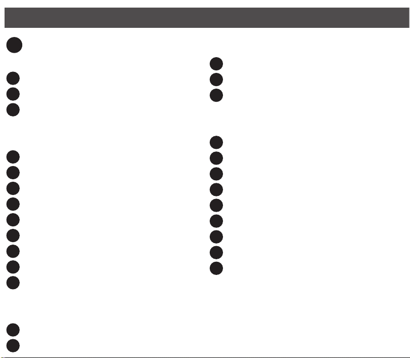
Hardware Review
CE920L Front
1RS-232 Serial Port
2Link LED
3Power LED
CE920L Rear
4Power Jack
5HDBaseT Out Port
6Ethernet Port
7DisplayPort In Port
8USB Type-B Port
9Audio Out Port
10 Audio In Port
11 Long Reach Mode Switch
12 Firmware Upgrade Switch
CE920R Front
1RS-232 Serial Port
2Wake Up PC Pushbutton
3Video Out LED
4Link LED
5Power LED
CE920R Rear
6Power Jack
7HDBaseT In Port
8Ethernet Port
9DisplayPort Out Port
10 USB Type-A Ports
11 Audio Out Port
12 Audio In Port
13 Long Reach Mode Switch
14 Firmware Upgrade Switch
B
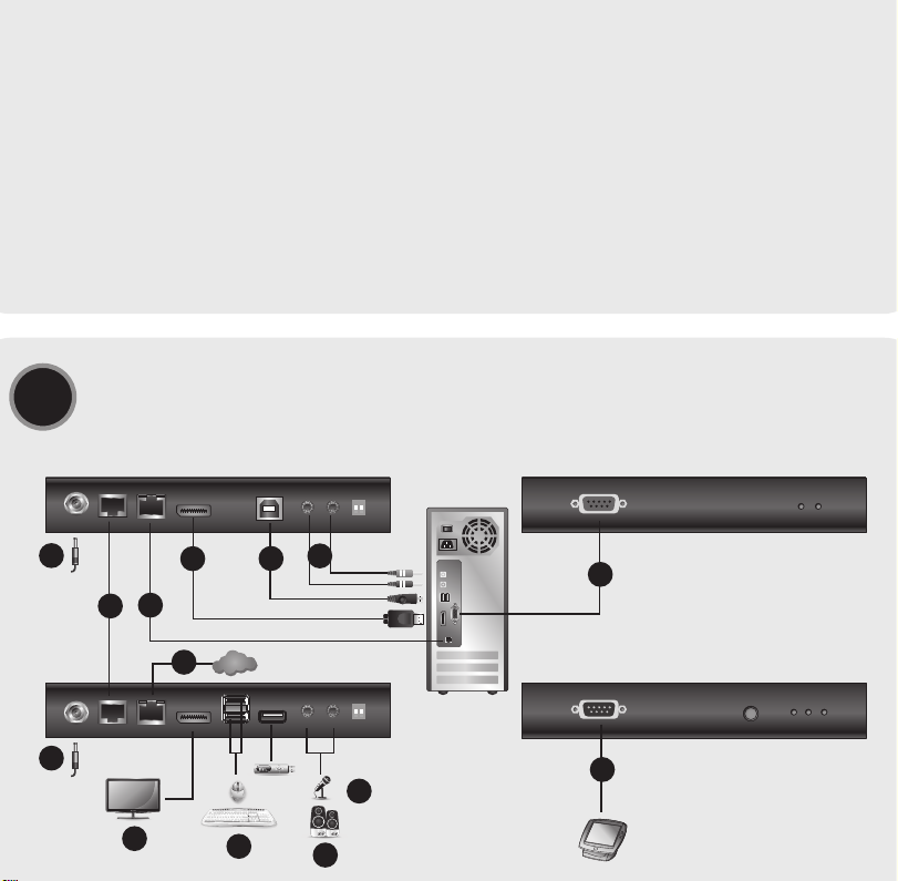
Hardware Installation
Before you proceed with the setup, make sure that all the equipment to
be connected is powered off. To install the CE920, refer to the installation
diagram above and do the following:
1Connect one end of the supplied microphone cable to the rear of the
CE920L, and the other end to a local computer. Do the same using the
supplied speaker cable.
2Connect the supplied USB cable to the USB Type-B Port on the CE920L, and
the other end to a USB Type-A Port on the local computer.
3Connect the supplied DisplayPort cable to the DisplayPort In Port on the
CE920L, and the other end to the local computer.
4Plug one end of an Ethernet cable into the HDBaseT Out Port on the
CE920L, and the other end into the HDBaseT In Port on the CE920R.
5Plug one of the supplied power adapters into a power source, and then
plug the adapter’s power cable into the Power Jack on the CE920L.
6Use a DisplayPort Cable to connect the DisplayPort Out Port on the CE920R
to your monitor.
7Plug USB devices (mouse, keyboard, etc.) into their respective USB ports on
the CE920R.
8Plug the microphone and speakers into their respective audio ports on the
CE920R.
9To gain access via LAN/WAN, use an Ethernet cable to connect the Ethernet
Port of the CE920L to the computer, and then use another Ethernet cable
to connect the Ethernet Port of the CE920R to a network switch.
10 Plug the second adapter into a power source, and then plug the adapter’s
power cable into the Power Jack on the CE920R.
11 To use the Wake Up PC Pushbutton, use an RS-232 serial cable to connect
the RS-232 Serial Port on the CE920L to the local computer.
12 To control the local computer with a serial device, connect the RS-232 Port
on the CE920L to the local computer, as illustrated in step 11, and then
connect a hardware/software controller to the RS-232 Port on the CE920R.
13 To extend video of 1080p up to 150 m, put either the CE920L or CE920R’s
Long Reach Mode Switch to ON.
Operation
Rack Mounting
1. Using the screws from the supplied Mounting Kit, secure the mounting
bracket to the top or bottom of the CE920.
2. Using self-prepared screws, secure the mounting bracket to a preferred
location on the rack.
Note: Rack screws are not provided. ATEN recommends using M5 Phillips
recessed screws.
BHardware Installation
© Copyright 2018 ATEN®International Co., Ltd.
ATEN and the ATEN logo are trademarks of ATEN International Co., Ltd. All rights reserved. All
other trademarks are the property of their respective owners.
Part No. PAPE-1223-M30G Printing Date: 04/2018
USB DisplayPort HDBaseT 2.0 KVM Extender
Quick Start Guide
CE920
CE920 USB DisplayPort HDBaseT 2.0 KVM Extender www.aten.com
ATEN VanCryst™
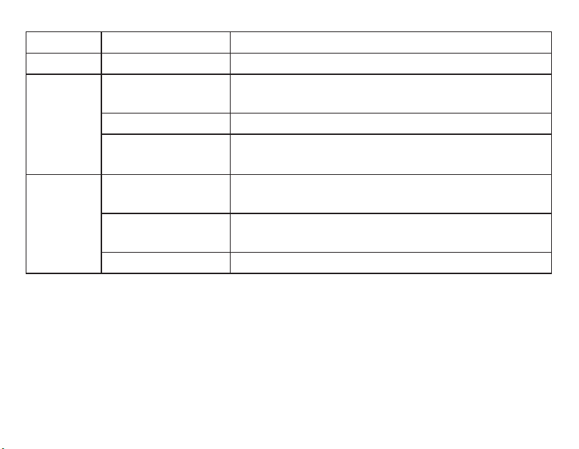
LED Display and System Status
LED LED Display System Status
Power Lights green The system is receiving power.
Link
Lights orange The connection between the CE920L and
CE920R is stable.
Flashes orange The HDBaseT transmission is unstable.
Off The connection between the CE920L and
CE920R is off.
Video Out
Lights orange The video display is normal and secured with
HDCP.
Flashes orange The video display is normal but not secured
with HDCP.
Off The video is not displayed.
Note: The Video Out LED is only available on the CE920R.
CE920 Package Contents
1 CE920L USB DisplayPort HDBaseT 2.0
KVM Extender (Local Unit)
1 CE920R USB DisplayPort HDBaseT 2.0
KVM Extender (Remote Unit)
1 Microphone Cable
1 Speaker Cable
1 USB Type-A to Type-B Cable
1 DisplayPort Cable
2 Mounting Kits
8 Foot Pads
2 Power Adapters
1 User Instructions
CE920L Package Contents
1 CE920L USB DisplayPort
HDBaseT 2.0 KVM Extender
(Local Unit)
1 Microphone Cable
1 Speaker Cable
1 USB Type-A to Type-B Cable
1 DisplayPort Cable
1 Mounting Kit
4 Foot Pads
1 Power Adapter
1 User Instructions
CE920R Package Contents
1 CE920R USB DisplayPort
HDBaseT 2.0 KVM Extender
(Remote Unit)
1 Mounting Kit
4 Foot Pads
1 Power Adapter
1 User Instructions
Support and Documentation Notice
All information, documentation, firmware,
software utilities, and specifications
contained in this package are subject to
change without prior notification by
the manufacturer.
To reduce the environmental impact of our
products, ATEN documentation and software
can be found online at
http://www.aten.com/download/
Technical Support
www.aten.com/support
이 기기는 업무용(A급) 전자파적합기기로서 판매자 또는
사용자는 이 점을 주의하시기 바라며, 가정외의 지역에
서 사용하는 것을 목적으로 합니다.
Scan for
more information
EMC Information
FEDERAL COMMUNICATIONS COMMISSION INTERFERENCE
STATEMENT:
This equipment has been tested and found to comply with the limits
for a Class A digital device, pursuant to Part 15 of the FCC Rules.
These limits are designed to provide reasonable protection against
harmful interference when the equipment is operated in a commercial
environment. This equipment generates, uses, and can radiate radio
frequency energy and, if not installed and used in accordance with
the instruction manual, may cause harmful interference to radio
communications. Operation of this equipment in a residential area
is likely to cause harmful interference in which case the user will be
required to correct the interference at his own expense.
FCC Caution: Any changes or modifications not expressly approved by
the party responsible for compliance could void the user's authority to
operate this equipment.
Warning: Operation of this equipment in a residential environment
could cause radio interference.
Suggestion: Shielded twisted pair (STP) cables must be used with the
unit to ensure compliance with FCC & CE standards.
This device complies with Part 15 of the FCC Rules. Operation is subject
to the following two conditions: (1) this device may not cause harmful
interference, and (2) this device must accept any interference received,
including interference that may cause undesired operation.
21 3 4 5
1 2 3
4 5 6 8 9 10
13 1410 11 12
711 12
6 7 8 9
CE920L Front View
CE920L Rear View
CE920R Front View
CE920R Rear View
Local PC
CE920L Rear View
CE920R Rear View
5
10
678
13
4
Internet/
LAN
9
1
2
9
11
12
3
A
Aperçu du matériel
Avant du CE920L
1Port série RS-232
2LED Liaison
3LED d'alimentation
Arrière du CE920L
4Fiche d'alimentation
5Port de sortie HDBaseT
6Port Ethernet
7Port d’entrée DisplayPort
8Port USB Type B
9Port de sortie audio
10 Port d’entrée audio
11 Commutateur de mode longue
portée
12 Commutateur de mise à niveau du
firmware
Avant du CE920R
1Port série RS-232
2Bouton poussoir de réveil PC
3LED de sortie vidéo
4LED Liaison
5LED d'alimentation
Arrière du CE920R
6Fiche d'alimentation
7Port d’entrée HDBaseT
8Port Ethernet
9Port de sortie DisplayPort
10 Ports USB Type A
11 Port de sortie audio
12 Port d’entrée audio
13 Commutateur de mode longue
portée
14 Commutateur de mise à niveau du
firmware
B
Installation du matériel
Avant de procéder à la configuration, assurez-vous que tout les équipements
à connecter sont éteints. Pour installer le CE920, reportez-vous au schéma
d’installation ci-dessus et effectuez les étapes suivantes :
1Branchez une extrémité du câble microphone fourni à l’arrière du CE920L
et l'autre extrémité sur un ordinateur local. Faites de même en utilisant le
câble d'enceintes fourni.
2Branchez le câble USB fourni sur le port USB Type B du CE920L et l'autre
extrémité sur un port USB Type A de l'ordinateur local.
3Branchez le câble DisplayPort fourni sur le port d’entrée DisplayPort du
CE920L et l'autre extrémité sur l'ordinateur local.
4Branchez une extrémité d’un câble Ethernet sur le port de sortie HDBaseT
du CE920L, et l'autre extrémité sur le port d’entrée HDBaseT du CE920R.
5Branchez l'un des adaptateurs d'alimentation fournis sur une source
d'alimentation, puis branchez le câble d'alimentation de l'adaptateur sur la
prise d'alimentation du CE920L.
6Utilisez un câble DisplayPort pour raccorder le port de sortie DisplayPort du
CE920R à votre moniteur.
7Branchez les périphériques USB (souris, clavier, etc.), sur leurs ports USB
respectifs du CE920R.
8Branchez le microphone et les enceintes sur leurs ports audio respectifs du
CE920R.
9Pour obtenir l’accès via LAN/WAN, utilisez un câble Ethernet afin de
raccorder le port Ethernet du CE920L à l'ordinateur, puis utilisez un
autre câble Ethernet pour raccorder le port Ethernet du CE920R à un
commutateur réseau.
10 Branchez le second adaptateur sur une source d'alimentation, puis
branchez le câble d'alimentation de l'adaptateur sur la prise d'alimentation
du CE920R.
11 Pour utiliser le bouton-poussoir de réveil du PC, servez-vous d’un câble série
RS-232 afin de raccorder le port série RS-232 du CE920L à l'ordinateur
local.
12 Pour contrôler l'ordinateur local avec un périphérique série, raccordez le
port RS-232 du CE920L à l'ordinateur local, comme illustré à l'étape 11,
puis raccordez un contrôleur matériel / logiciel au port RS-232 du CE920R.
13 Pour étendre la vidéo 1080p jusqu'à 150 m, activez le commutateur du
mode sur le CE920L ou sur le CE920R.
Fonctionnement
Montage en rack
1. À l'aide des vis fournies dans le kit de montage, fixez le support de montage
en haut ou en bas du CE920.
2. À l'aide de vis auto-taraudeuses, fixez le support de montage à
l'emplacement souhaité sur le rack.
Remarque : Les vis de rack ne sont pas fournies. ATEN recommande l’utilisation
de vis encastrées M5 Phillips.
Affichage LED et état du système
LED Affichage LED État système
Alimentation S’illumine en vert Le système reçoit l’alimentation.
Lien
S’illumine en
orange
La connexion entre le CE920L et le CE920R
est stable.
Clignote en
orange La transmission HDBaseT est instable.
Désact. La connexion entre le CE920L et le CE920R
est désactivée.
Sortie Vidéo
S’illumine en
orange
L’affichage vidéo est normal et sécurisé avec
HDCP.
Clignote en
orange
L’affichage vidéo est normal mais n’est pas
sécurisé avec HDCP.
Désact. La vidéo n'est pas affichée.
Remarque : La LED de sortie vidéo n’est disponible que sur le CE920R.
A
Hardwareübersicht
CE920L – Vorderseite
1Serieller RS-232-Anschluss
2Verbindung-LED
3Betriebsanzeige-LED
CE920L – Rückseite
4Netzanschluss
5HDBaseT-Ausgang
6Ethernet-Port
7DisplayPort-Eingang
8USB-Type-B-Port
9Audioausgang
10 Audioeingang
11 Reichweitenschalter
12 Firmware-Aktualisierungsschalter
CE920R – Vorderseite
1Serieller RS-232-Anschluss
2Drucktaste zur PC-Reaktivierung
3Videoausgang-LED
4Verbindung-LED
5Betriebsanzeige-LED
CE920R – Rückseite
6Netzanschluss
7HDBaseT-Eingang
8Ethernet-Port
9DisplayPort-Ausgang
10 USB-Type-A-Ports
11 Audioausgang
12 Audioeingang
13 Reichweitenschalter
14 Firmware-Aktualisierungsschalter
B
Hardwareinstallation
Stellen Sie sicher, dass alle anzuschließenden Geräte ausgeschaltet sind, bevor
Sie mit der Einrichtung fortfahren. Beachten Sie zur Installation des CE920 die
obige Installationsabbildung und gehen Sie wie folgt vor:
1Verbinden Sie ein Ende des mitgelieferten Mikrofonkabels mit der Rückseite
des CE920L und das andere Ende mit einem lokalen Computer. Gehen Sie
ebenso mit dem mitgelieferten Lautsprecherkabel vor.
2Verbinden Sie das mitgelieferte USB-Kabel mit dem USB-Type-B-Anschluss
am CE920L und das andere Ende mit einem USB-Type-A-Port am lokalen
Computer.
3Verbinden Sie das mitgelieferte DisplayPort-Kabel mit dem DisplayPort-
Eingang am CE920L und das andere Ende mit dem lokalen Computer.
4Schließen Sie ein Ende eines Ethernet-Kabels am HDBaseT-Ausgang am
CE920L und das andere Ende am HDBaseT-Eingang am CE920R an.
5Verbinden Sie ein Ende der mitgelieferten Netzteile mit einer Stromquelle
und das Netzkabel des Netzteils mit dem Stromanschluss am CE920L.
6Verbinden Sie den DisplayPort-Ausgang am CE920R über ein DisplayPort-
Kabel mit Ihrem Monitor.
7Schließen Sie USB-Geräte (Maus, Tastatur usw.) an den entsprechenden
USB-Ports am CE920R an.
8Schließen Sie Mikrofon und Lautsprecher an die entsprechenden
Audioanschlüsse am CE920R an.
9Gewähren Sie Zugriff über LAN/WAN, indem Sie den Ethernet-Anschluss
des CE920L über ein Ethernet-Kabel mit dem Computer und dann den
Ethernet-Port des CE920R über ein weiteres Ethernet-Kabel mit einem
Netzwerk-Switch verbinden.
10 Schließen Sie das zweite Netzteil an eine Stromversorgung an, verbinden
Sie dann das Netzkabel des Netzteils mit dem Stromanschluss am CE920R.
11 Verwenden Sie die PC-aufwecken-Drucktaste, indem Sie den seriellen
RS-232-Anschluss am CE920L über ein serielles RS-232-Kabel mit dem
lokalen Computer verbinden.
12 Steuern Sie den lokalen Computer mit einem seriellen Gerät, indem Sie
den RS-232-Port am CE920L wie in Schritt 11 dargestellt mit dem lokalen
Computer und dann einen Hardware/Software-Controller mit dem RS-232-
Port am CE920R verbinden.
13 Erweitern Sie das 1080p-Video bis 150 m, indem Sie den
Reichweitenschalter am CE920L oder CE920R aktivieren.
Bedienung
Rackmontage
1. Befestigen Sie die Montagehalterung mit den Schrauben aus dem
mitgelieferten Montageset an der Ober- oder Unterseite des CE920.
2. Befestigen Sie die Montagehalterung mit vorbereiteten Schrauben an einer
bevorzugten Stelle am Rack.
Hinweis: Rackschrauben sind nicht im Lieferumfang enthalten. ATEN
empfiehlt die Verwendung vertiefter M5-Phillips-Schrauben.
LED-Anzeige und Systemstatus
LED LED-Anzeige Systemstatus
Stromversorgung Leuchtet grün Das System wird mit Strom versorgt.
Verbindung
Leuchtet orange Die Verbindung zwischen CE920L und
CE920R ist stabil.
Blinkt orange Die HDBaseT-Übertragung ist nicht stabil.
Aus Die Verbindung zwischen CE920L und
CE920R ist inaktiv.
Videoausgang
Leuchtet orange Die Videoanzeige ist normal und mit
HDCP gesichert.
Blinkt orange Die Videoanzeige ist normal, aber nicht
mit HDCP gesichert.
Aus Das Video wird nicht angezeigt.
Hinweis: Die Videoausgang-LED ist nur am CE920R verfügbar.
A
Presentación del
hardware
Parte delantera CE920L
1Puerto serie RS-232
2LED de enlace
3LED de alimentación
Parte posterior CE920L
4Conector de alimentación
5Puerto de salida HDBaseT
6Puerto Ethernet
7Puerto de entrada DisplayPort
8Puerto USB Tipo B
9Puerto de salida de audio
10 Puerto de entrada de audio
11 Conmutador de modo de largo
alcance
12 Interruptor de actualización de
firmware
Parte delantera CE920R
1Puerto serie RS-232
2Pulsador reactivación del PC
3LED de salida de vídeo
4LED de enlace
5LED de alimentación
Parte posterior CE920R
6Conector de alimentación
7Puerto de entrada HDBaseT
8Puerto Ethernet
9Puerto de salida DisplayPort
10 Puertos USB Tipo A
11 Puerto de salida de audio
12 Puerto de entrada de audio
13 Conmutador de modo de largo
alcance
14 Interruptor de actualización de
firmware
B
Instalación de hardware
Antes de continuar con la configuración, asegúrese de que todo el equipo
conectado está apagado. Para instalar el CE920, consulte el diagrama de
instalación anterior y haga lo siguiente:
1Conecte un extremo del cable de micrófono suministrado a la parte
posterior del CE920L y el otro extremo a un ordenador local. Realice el
mismo procedimiento con el cable de altavoz suministrado.
2Conecte el cable USB suministrado al puerto USB Tipo B del CE920L y el
otro extremo al puerto USB Tipo A del ordenador local.
3Conecte el cable DisplayPort suministrado al puerto de entrada DisplayPort
del CE920L y el otro extremo al ordenador local.
4Conecte un extremo de un cable Ethernet en el puerto de salida HDBaseT
del CE920L y el otro extremo en el puerto de entrada HDBaseT del CE920R.
5Enchufe uno de los adaptadores de alimentación suministrados en una
fuente de alimentación y a continuación conecte el cable de alimentación
del adaptador en la toma del CE920L.
6Utilice un cable DisplayPort para conectar el puerto de salida DisplayPort
situado en el CE920R a su monitor.
7Conecte los dispositivos USB (ratón, teclado, etc.) en sus respectivos puertos
USB en el CE920R.
8Conecte el micrófono y los altavoces en sus respectivos puertos de audio en
el CE920R.
9Para acceder a través de LAN/WAN, utilice un cable Ethernet para conectar
le puerto Ethernet del CE920L al ordenador y a continuación utilice
otro cable Ethernet para conectar el puerto Ethernet del CE920R a un
conmutador de red.
10 Enchufe un segundo adaptador en la fuente de alimentación y a
continuación, conecte el cable de alimentación del adaptador en la toma
del CE920R.
11 Para utilizar el pulsador reactivación del PC, utilice un cable serie RS-232
para conectar el puerto serie RS-232 en el CE920L al ordenador local.
12 Para controlar el ordenador local con un dispositivo serie, conecte el puerto
RS-232 en el CE920L al ordenador local, tal y como se muestra en el paso
11, y a continuación, conecte un controlador de hardware/software al
puerto RS-232 Port del CE920R.
13 Para extender el vídeo de 1080p hasta 150 m, configure el conmutador de
modo de largo alcance del CE920L o CE920R en posición ON (activado).
Funcionamiento
Montaje en bastidor
1. Utilizando los tornillos del kit de instalación suministrado, asegure el soporte
de montaje en la parte superior o inferior del CE920.
2. Utilizando los tornillos que Ud. prepare, asegure el soporte de montaje a la
ubicación preferida del bastidor.
Nota: Los tornillos del rack no se proporcionan. ATEN recomienda el uso
detornillos de estrella (Phillips) M5 de cabeza avellanada.
Visualización LED y Estado del Sistema
LED Visualización
LED Estado del sistema
Alimentación Se ilumina en
verde El sistema recibe alimentación.
Enlace
Se ilumina en
naranja
La conexión entre el CE920L y el CE920R es
estable.
Parpadea en
naranja La transmisión HDBaseT es inestable.
Apagado La conexión entre el CE920L y el CE920R está
desactivada.
Salida de
vídeo
Se ilumina en
naranja
La visualización de vídeo es normal y protegida
mediante HDCP.
Parpadea en
naranja
La visualización de vídeo es normal, pero no
está protegida mediante HDCP.
Apagado No se muestra el vídeo.
Nota: El LED de salida de vídeo solo está disponible en el CE920R.
A
Descrizione hardware
Pannello frontale di CE920L
1Porta seriale RS-232
2LED Link (Collegamento)
3LED alimentazione
Pannello posteriore di CE920L
4Connettore di alimentazione
5Porta uscita HDBaseT
6Porta Ethernet
7Porta ingresso DisplayPort
8Porta USB Tipo B
9Porta di uscita audio
10 Porta di ingresso audio
11 Interruttore modalità lunga portata
12 Interruttore aggiornamento firmware
Pannello frontale di CE920R
1Porta seriale RS-232
2Tasto di attivazione PC
3LED uscita video
4LED Link (Collegamento)
5LED alimentazione
Pannello posteriore di CE920R
6Connettore di alimentazione
7Porta ingresso HDBaseT
8Porta Ethernet
9Porta uscita DisplayPort
10 Porte USB Tipo A
11 Porta di uscita audio
12 Porta di ingresso audio
13 Interruttore modalità lunga portata
14 Interruttore aggiornamento
firmware
B
Installazione dell'hardware
Prima di procedere con l'installazione, assicurarsi che tutte le attrezzature da
collegare siano spente. Per eseguire l’installazione di CE920, fare riferimento
allo schema di installazione di cui sopra e procedere come segue:
1Collegare una estremità del cavo microfono fornito in dotazione al pannello
posteriore di CE920L e l'altra estremità al computer locale. Eseguire la
stessa procedura per il cavo altoparlanti fornito in dotazione.
2Collegare il cavo USB fornito in dotazione alla porta USB di tipo B di
CE920L e l'altra estremità a una porta USB di tipo A del computer locale.
3Collegare il cavo DisplayPort fornito in dotazione alla porta ingresso
DisplayPort di CE920L e l'altra estremità al computer locale.
4Collegare una estremità di un cavo Ethernet alla porta uscita HDBaseT di
CE920L e l'altra estremità alla porta HDBaseT di CE920R.
5Collegare uno degli adattatori di corrente forniti in dotazione a una presa
di corrente, quindi collegare il cavo di alimentazione dell'adattatore al
connettore di alimentazione di CE920L.
6Utilizzare un cavo DisplayPort per collegare la porta uscita DisplayPort di
CE920R al monitor.
7Collegare i dispositivi USB (mouse, tastiera, eccetera) alle rispettive porte
USB di CE920R.
8Collegare il microfono e gli altoparlanti alle rispettive porte audio di
CE920R.
9Per eseguire l’accesso tramite LAN/WAN, utilizzare un cavo Ethernet per
collegare la porta Ethernet di CE920L al computer, quindi utilizzare un altro
cavo Ethernet per collegare la porta Ethernet di CE920R a uno switch di
rete.
10 Collegare il secondo adattatore a una presa di corrente, quindi collegare
il cavo di alimentazione dell'adattatore al connettore di alimentazione di
CE920R.
11 Per utilizzare il tasto di attivazione PC, utilizzare un cavo seriale RS-232 per
collegare la porta seriale RS-232 di CE920L al computer locale.
12 Per controllare il computer locale con un dispositivo seriale, collegare la
porta RS-232 di CE920L al computer locale, come illustrato al punto 11,
quindi collegare un controller hardware/software alla porta RS-232 di
CE920R.
13 Per estendere il video 1080p fino a 150 m, impostare su ON l'interruttore
della modalità lunga portata di CE920L o di CE920R.
Funzionamento
Montaggio su rack
1. Utilizzando le viti del kit di montaggio fornito in dotazione, fissare la staffa
di montaggio alla parte superiore o inferiore di CE920.
2. Utilizzando delle viti preparate in precedenza, fissare la staffa di montaggio
sulla posizione preferita del rack.
Nota: Le viti rack non sono fornite in dotazione. ATEN raccomanda l’utilizzo di
viti incassate Phillips (testa a croce) M5.
Display LED e Stato del sistema
LED Display a LED Stato del sistema
Alimentazione Acceso di colore
verde Il sistema sta ricevendo energia elettrica.
Collegamento
Acceso di colore
arancione
Il collegamento tra CE920L e CE920R è
stabile.
Lampeggia di
colore arancione La trasmissione HDBaseT non è stabile.
Off Il collegamento tra CE920L e CE920R è
disattivato.
Uscita video
Acceso di colore
arancione
La visualizzazione video è normale e
protetto tramite HDCP.
Lampeggia di
colore arancione
La visualizzazione video è normale ma non è
protetto tramite HDCP.
Off Il video non è visualizzato.
Nota: Il LED uscita video non è disponibile su CE920R.
AHardware Review