WIFO K53a Operator's manual

WIFO-Anema B.V.
Hegebeintumerdyk 37 – 9172 GP Ferwert – Holland
Telefoon (0031) 518411318 – Telefax (0031) 518411563
www.wifo.nl – email: [email protected]
Manual and safety instructions
K53a-(z)/K53c-(z)/DKB-25-(z)/DKD-35-(z)
Box rotator
GB
K53a-(z) K53c-(z)
DKB-25-(z)
DKD-35-(z)


1
English
Table of contents
1. TO THE USER ...................................................................................................................................................................... 2
1.1 INTRODUCTION ...................................................................................................................................................................... 2
1.2 SAFETY PRECAUTIONS AND WARNINGS........................................................................................................................................ 3
1.2.1 Safety precautions .................................................................................................................................................... 3
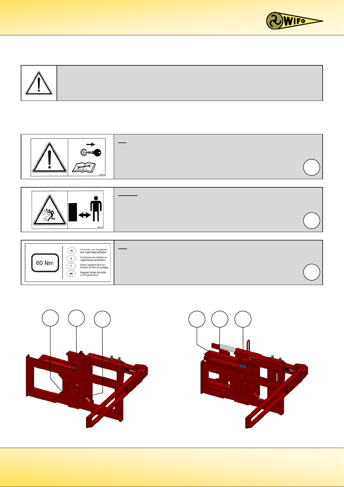
1.2.2 Safety stickers and warning signs............................................................................................................................. 5
1.2.3 Placement of the safety stickers on the machine ..................................................................................................... 5
1.3 PURPOSE OF USE .................................................................................................................................................................... 6
1.4 LIABILITY............................................................................................................................................................................... 7
1.5 WARRANTY ........................................................................................................................................................................... 7
2. TECHNICAL DATA .............................................................................................................................................................. 8
2.1 GENERAL TECHNICAL DATA...................................................................................................................................................... 8
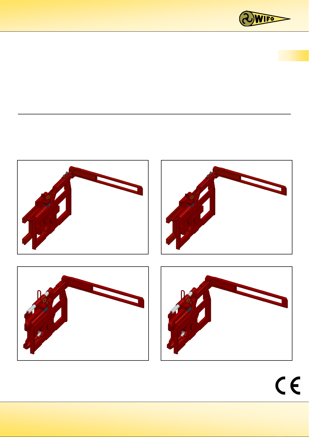
2.2 K53A AND K53C................................................................................................................................................................... 9
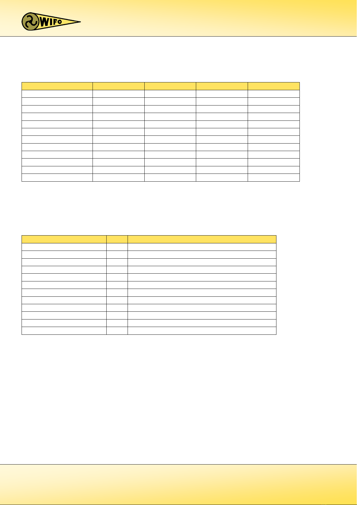
2.2.1 Parts list ................................................................................................................................................................... 9
2.3 K53A-Z AND K53C-Z (INDUSTRIAL MODEL)............................................................................................................................... 10
2.3.1 Parts list ................................................................................................................................................................. 10
2.3.2 Commencement of operation K53a-(z)/K53c-(z) .................................................................................................... 11
2.4 K53A-UK AND K53C-UK ........................................................................................................................................................ 12
2.4.1 Parts list ................................................................................................................................................................. 12
2.4.2 Commencement of operation K53a-uk/K53c-uk..................................................................................................... 13
2.5 DKB-25 AND DKD-35 ......................................................................................................................................................... 14
2.5.1 Parts list .................................................................................................................................................................. 14
2.6 DKB-25-Z AND DKD-35-Z (INDUSTRIAL MODEL)...................................................................................................................... 15
2.6.1 Parts list .................................................................................................................................................................. 15
2.6.2 Provisions for connecting DKB-25-(z)/DKD-35-(z) ................................................................................................... 16
2.6.3 Commencement of operation DKB-25-(z)/DKD-35-(z) ............................................................................................ 17
2.7 SPARE PARTS ....................................................................................................................................................................... 18
3. FAULTS AND MAINTENANCE ........................................................................................................................................... 19
3.1 PREVENTIVE MAINTENANCE AND LUBRICATION .......................................................................................................................... 19
3.2 TROUBLESHOOTING.............................................................................................................................................................. 20
3.3 WORK TO BE CARRIED OUT BY A COMPETENT MECHANIC.............................................................................................................. 21
3.3.1 Instructions for replacing the sleeve bearing of K53a/K53c/DKB-25/DKD-35 ........................................................ 21
3.3.2 Instructions for replacing the tapered roller bearings of K53a-z/K53c-z/DKB-25-z/DKD-35-z ............................... 22

2
1. To the user
1.1 Introduction
This manual gives information about the commencement of operation, use and maintenance of your newly
purchased WIFO box rotator. Also included in this manual are a number of safety instructions to create a safe
working environment.
WIFO-Anema B.V. continuously aims to improve its products. WIFO-Anema B.V. reserves the right to introduce any
changes and improvements deemed necessary without prior notice.
Please read the manual thoroughly and observe the safety procedures before putting the unit into operation.
Contact your dealer for any further questions or concerns you may have.
We hope you will enjoy working with your WIFO box rotator.
Keep this manual in a safe place for future reference!
WIFO-Anema B.V.
Dealer:
PLEASE NOTE:
Carefully read this manual before you put the machine into operation and act upon all directions that are
given. This is to guarantee its safe, trouble-free operation.

3
1.2 Safety precautions and warnings
Please read this manual before you put the machine into operation for the first time, and observe the safety
instructions at all times. The most important instructions are marked with a symbol.
Any person in charge of the commencement of operation, the operation itself or the maintenance of the machine is
urged to carefully read and observe the following instructions.
1.2.1 Safety precautions
Centre the load;
Place the forks as widely as possible;
Position the third fork against the side of the box.
Restrict driving with the load in elevated position;
Do no tilt the load during transport;
Slightly tilt the forklift mast backwards during transport.
Do not allow any person to ride on the forks.
This symbol is used for all important safety instructions throughout this manual. Carefully observe the
instructions and be very cautious.
This symbol is used for all important actions that should not be carried out under any circumstances.
Carefully observe these prohibitions.
Do not allow any person to stand under the load, and
stay out of the working area of the box rotator.

4
Keep at least 150 mm of the fork positioner of the folding
fork in the slot and secure the same using the two bolts
and lock nuts (140Nm).
Operate the box rotator from the driver’s seat of the
forklift/tractor only.
Park the forklift truck / mast with the box rotator in the lowest position only. Make sure that unexpected
movements are ruled out if the forklift truck / tractor is not being used. Place the box rotator on its back on
a flat, stable surface after it has been removed from the forklift truck / mast for storage.
For tilting work, use only durable boxes with flooring or grooves.
Make sure the operating lever for rotating is not mixed up with any other operating lever to prevent
inadvertent tilting or side-shifting. Only the side-shift function remains in the event of a power cut while
operating an electrically controlled valve. Disable the tilting motion with the safety pin placed in the block
behind the cylinder if the box rotator is not being used.
Make sure the hydraulic hoses and any power cables do not get jammed and that the box rotator is able to
move freely.
During the controlled tilting action, be aware of the back-tilt moment of the rotating cylinder.

5
1 2 3
1 2
3
1.2.2 Safety stickers and warning signs
Several safety stickers have been put onto the machine. The meaning of the stickers on the machine is as follows:
1.2.3 Placement of the safety stickers on the machine
Figure 1.2.1-Position safety stickers for K53a-(z) en K53c-(z) Figure 1.2.2-Position safety stickers DKB-25-(z) en DKD-35-(z)
NB:
Regularly tighten the bolts of the guide block using the correct tightening
moment (60Nm)!
3
NB:
Please read the instructions from the manual prior to any maintenance to the
machine!
Turn of the engine and remove the key from the ignition for the time
maintenance on the machine is carried out!
1
Danger:
Always keep a safe distance from the machine!
2
A safe working environment also requires personnel to be well-informed about the various safety stickers on
the machine. Be aware of the hazards they warn you to look out for.
Replace any loose, illegible or missing stickers.

6
1.3 Purpose of use
The WIFO box rotator is exclusively used for transporting and sideways tilting boxes with flooring or grooves,
provided that the overall weight of the box including its load does not exceed the carrying capacity of the box
rotator. The box rotator must be attached to a FEM II (K53a and DKB-25) or FEM III (K53c and DKD-35) fork carrier of
a forklift truck or forklift mast.
Do not use the box rotator for carrying people under any circumstances!
The overall weight of the box rotator including its load may not exceed the capacity of the forklift truck or
the forklift mast. (See the name plate on the forklift truck/forklift mast)

7
1.4 Liability
Any person working with or on the machine must have read this manual. The machine is to be used for its intended
purpose only. Included in the intended purpose are, among other things:
1. Work must be carried out in accordance with the directions and within the functional restrictions (e.g.
maximum hydraulic working pressure) as outlined in the regulations. Use only sound and appropriate tools.
2. Electric/electronic equipment and accessories (e.g. cables) must be treated in accordance with the general
accepted policy for using non-waterproof portable electric and electronic equipment, such as:
a) Storing and keeping in a clean, dry environment away from rodents and the like; and
b) Protecting the equipment against severe, uncushioned shocks and water (precipitation).
3. Use only original or compatible spare parts. Such parts must be assembled as directed (e.g. by observing the
recommended tightening moments). Spare parts (as well as lubricants) are considered compatible only if
explicitly approved by WIFO or in the event that the customer is able to prove they possess the required
properties for the purpose(s) they are used.
4. Use only lubricants that meet the specifications as described in the directions.
5. Always observe the local regulations in terms of accident prevention, safety, traffic and transport.
6. Only trained personnel with knowledge of the possible hazards have permission to work with/on the
machine.
7. WIFO-Anema B.V. will assume no liability in any shape or form for losses or damage caused following
modifications to the machine, which have not been explicitly approved by WIFO.
1.5 Warranty
WIFO-Anema B.V. guarantees the soundness of its products in terms of materials used and/or structural defects.
However, in any event this warranty is limited to the free-of-charge replacement or repairs of the defect product, or
part thereof. WIFO-Anema B.V. assumes no liability for any loss or damage arising from faulty deliveries and/or the
breakdown of purchased goods before the warranty period has expired. The warranty period for this product is
twelve months.
Noncompliance with the rules and directions from this manual will be considered as serious negligence, for
the consequences of which WIFO-Anema B.V. accepts no liability whatsoever. In such cases, the user will
bear the full risk of his actions.
WIFO-Anema B.V. is continuously working on the improvement of its products. For that reason, WIFO-
Anema B.V. reserves the right to introduce any changes and improvements deemed necessary without
prior notice. However, it does not imply an obligation to make any such changes or improvements to
machines bought by customers in the past.

8
2. Technical data
2.1 General technical data
1Plug-in/foldaway model.
2The back-tilt moment has been calculated at 18 Mpa (180 bar) working pressure.
3Two positions from inside fork to centre of rotating shaft.
4Continuously adjustable from inside fork to centre of rotating shaft.
Model Letter Description
K53a/K53c/DKB-25/DKD-35 L Rotating to the left
R Rotating to the right
Z Industrial model with adjustable tapered roller bearings
V Front-loader/far reaching model
K53a/K53c I Plug-in third fork
O Foldaway third fork
UK Plug-in fourth fork (top fork)
DKB-25/DKD-35
E
Electrically controlled reversing valve
S 4-hose connection
Table 2.1.2-Description data on model plate
Model K53a-(z) K53c-(z) DKB-25-(z) DKD-35-(z)
Max. carrying capacity 2500 kg 3500 kg 2500 kg 3500 kg
Weight
1
235/265 kg
310/345 kg
350 kg 425 kg
Max. working pressure 22Mpa (220 bar) 22Mpa (220 bar) 22Mpa (220 bar) 22Mpa (220 bar)
Back-tilt moment
2
6,84 KNm 6,84 KNm 6,84 KNm 6,84 KNm
Center of gravity 131/166mm
132/146mm 129 mm 135 mm
Frontal extension length 160 mm 170 mm 170 mm 180 mm
Height of the fork carrier 407 mm (FEM II) 508 mm (FEM III) 407 mm (FEM II) 508 mm (FEM III)
Rotation angle 180° 180° 180° 180°
Fork carrier width 1000 mm 1200 mm 1000 mm 1200 mm
Side-shift no no yes yes
Third fork plug-in
3
675 of 775 mm 775 of 875 mm - -
Third fork foldaway
4
580 – 800 mm 680 – 900 mm 580 – 800 mm 680 – 900 mm
Table 2.1.1-Various models of the WIFO box rotator

9
2.2 K53a and K53c
2.2.1 Parts list
No. Description Comments
Standard model
1
Back plate
-
2 Rotating cylinder -
3 Sleeve bearing -
4 Locking plate -
5 Guide block holder -
6 Guide Block -
7 Locking pin -
8 Clamping strip -
Model with gas spring folding fork
9 Fork carrier foldaway model -
10 Fork positioner folding fork -
11 Fork folding fork -
12 Pin folding fork -
13 Gas spring folding fork -
Plug-in fork model
14 Fork carrier plug-in model -
15 Plug-in fork -
16
Lock pin plug-in fork
-
These parts vary for the K53a and K53c
These parts are identical for the K53a and K53c
Table 2.2.1-Parts list for K53a and K53c
Figure 2.2.1-Parts drawing K53a and K53c

10
2.3 K53a-z and K53c-z (industrial model)
2.3.1 Parts list
No. Description Comments
Standard model
1 Back plate -
2 Rotating cylinder -
3 Screwable fork positioner -
4 Locking plate -
5 Guide block holder -
6 Guide block -
7 Locking pin -
8 Clamping strip -
9 Fork carrier folding fork -
10 Fork positioner folding fork -
11 Fork folding fork -
12 Pin folding fork -
13 Gas spring folding fork -
14 Tapered roller bearing back -
15 Tapered roller bearing fork -
16 Adjusting strip gear rack -
These parts vary for the K53a-z and K53c-z
These parts are identical for the K53a-z and K53c-z
Table 2.3.1-Parts list for K53a-z and K53c-z
Figure 2.3.1-Parts drawing for K53a-z and K53c-z

11
2.3.2 Commencement of operation K53a-(z)/K53c-(z)
1. Remove the clamping strip (8).
2. Remove the forks from the forklift truck or forklift mast.
3. Make sure the fork carrier is straight and clean.
4. Place the box rotator onto the fork carrier of the forklift truck or forklift mast.
5. Make sure the locking cam slots into the recess in the centre of the fork carrier. If no recess is available:
a) Grind such a recess, or
b) Grind the locking cam from the box rotator and attach a sound locking cam on the spot of an existing recess
in the fork carrier. In doing so, make sure the box rotator sits secure in the centre in front of the fork carrier,
so it is unable to slide sideways.
6. Attach the clamping strip (8) using two bolts M16 x 60. Secure these bolts tight! (140 Nm).
7. Check to make sure the hydraulic hoses are clean before connecting them to the rapid-action couplings, to
prevent any debris from entering the hydraulics of the machine.
8. Connect the hydraulic hoses to the dual-action connection on the fork carrier.
9. Remove the check nuts in the lower plate of the fork carrier of the box rotator. Suspend the forks to the fork
carrier and attach the check nuts.
10. Adjust the third fork, depending on the width of the boxes to be rotated.
11. Secure the third fork (of the foldaway model) using the pressure bolts; tightly secure first the bolts and then
the lock nuts (140 Nm). The fork positioner of the folding fork (10) must reach at least 150 mm into the slot.
A lock pin (16) is used for the plug-in model.
12. First remove the locking pin (7) at the back of the rotating cylinder before you start rotating. Place the pin
into the ring on the back plate, so it will not get lost.
13. Subsequently check that the hydraulic hoses can move freely and check that the system is not leaking oil.
14. Check the correct operation of the box rotator by controlling the hydraulic functions.
The WIFO box rotator is now ready to be used.

12
2.4 K53a-uk and K53c-uk
2.4.1 Parts list
No. Description Comments
Standard model
1 Back plate -
2 Rotating cylinder -
3 Sleeve bearing -
4 Locking plate -
5 Guide block holder -
6 Guide Block -
7 Locking pin -
8 Clamping strip -
9 Fork carrier plug-in model -
10 Plug-in fork -
11 Lock pin plug-in fork -
12 Top fork -
These parts vary for the K53a-uk and K53c-uk
These parts are identical for the K53a-uk and K53c-uk
Table 2.4.1-Parts list for K53a-uk and K53c-uk
Figure 2.4.1-Parts drawing for K53a-uk and K53c-uk

13
2.4.2 Commencement of operation K53a-uk/K53c-uk
The K53a-uk and K53c-uk box rotators can be equipped with a fourth fork (top fork), in order to rotate boxes without
bottom part/silts. The depth of the boxes should be 1200mm at most, so it will always support the top of the box.
1. Remove the clamping strip (8).
2. Remove the forks from the forklift truck or forklift mast.
3. Make sure the fork carrier is straight and clean.
4. Place the box rotator onto the fork carrier of the forklift truck or forklift mast.
5. Make sure the locking cam slots into the recess in the centre of the fork carrier. If no recess is available:
a) Grind such a recess, or
b) Grind the locking cam from the box rotator and attach a sound locking cam on the spot of an existing recess
in the fork carrier. In doing so, make sure the box rotator sits secure in the centre in front of the fork carrier,
so it is unable to slide sideways.
6. Attach the clamping strip (8) using two bolts M16x60. Secure these bolts tight! (140 Nm).
7. Check to make sure the hydraulic hoses are clean before connecting them to the rapid-action couplings, to
prevent any debris from entering the hydraulics of the machine.
8. Connect the hydraulic hoses to the dual-action connection on the fork carrier.
9. Remove the check nuts in the lower plate of the fork carrier of the box rotator. Suspend the forks to the fork
carrier and attach the check nuts.
10. Adjust the plug in fork (10), depending on the width of the boxes to be rotated.
11. Secure the plug in fork using the lock pin (11).
12. Adjust the topfork (12) to the desired position, depending on the level of the boxes to be rotated.
13. Keep about 50mm of space between the top of the box and the bottom of the fork if the box has been lifted
a little from the ground.
14. The fork positioner of the top fork must reach at least 150mm into the slot.
15. Secure the top fork using the pressure bolts; tightly secure first the bolts and then the lock nuts (140Nm).
16. Remove the locking pin (7) at the back of the rotating cylinder before you start rotating. Place the pin into
the ring on the back plate, so it will not get lost.
17. Subsequently check that the hydraulic hoses can move freely and check that the system is not leaking oil.
18. Check the correct operation of the box rotator by controlling the hydraulic functions.
The WIFO box rotator is now ready to be used.

14
2.5 DKB-25 and DKD-35
2.5.1 Parts list
No. Description Comments
Standard model
1 Back plate -
2 Rotating cylinder -
3 Sleeve bearing -
4
Locking plate
-
5 Guide Block holder -
6 Guide block -
7 Locking pin -
8 Clamping strip -
9 Fork carrier folding fork -
10 Fork positioner folding fork -
11 Fork folding fork -
12 Pin folding fork -
13 Gas spring folding fork -
14 Guide -
15 Guide Block -
17 Bearing bush guide -
18 Side-shift cylinder -
These parts vary for the DKB-25 and DKD-35
These parts are identical for the DKB-25 and DKD-35
Table 2.5.1-Parts list for DKB-25 and DKD-35
Figure 2.5.1-Parts drawing for DKB-25 and DKD-35

15
2.6 DKB-25-z and DKD-35-z (industrial model)
2.6.1 Parts list
No. Description Comments
Standard model
1 Back plate -
2 Rotating cylinder -
3 Screwable fork positioner -
4 Locking plate -
5 Guide block holder -
6 Guide Block -
7 Locking pin -
8 Clamping strip -
9 Fork carrier folding fork -
10 Fork positioner folding fork -
11 Fork folding fork -
12 Pin folding fork -
13 Gas spring folding fork -
14 Tapered roller bearing back plate side -
15 Tapered roller bearing fork carrier side -
16 Adjusting strip gear rack -
17 Bearing bush guide -
18 Side-shift cylinder -
19 Guide -
20 Guide lock
These parts vary for the DKB-25-z and DKD-35-z
These parts are identical for the DKB-25-z and DKD-35-z
Table 2.6.1-Parts list for DKB-25-z and DKD-35-z
Figure 2.6.1-Parts drawing for DKB-25-z and DKD-35-z

16
2.6.2 Provisions for connecting DKB-25-(z)/DKD-35-(z)
Model with four-hose connection
Model with electro-hydraulic valve
No. Description Comments
1 Feed-through Block four-hose connection -
1 Attachement electro-hydraulically controlled valve -
2 Electro-hydraulic valve -
3 Coil of the electro-hydraulic valve -
4 Switch on the forklift truck handle -
Table 2.6.2-Parts list connections for DKB-25-(z) and DKD-35-(z)

17
2.6.3 Commencement of operation DKB-25-(z)/DKD-35-(z)
1. Remove the clamping strips (8).
2. Remove the forks from the forklift truck or forklift mast.
3. Make sure the fork carrier is straight and clean.
4. Place the box rotator onto the fork carrier of the forklift truck or forklift mast.
5. Make sure the locking cam slots into the recess in the centre of the fork carrier. If no recess is available:
a) Grind such a recess, or
b) Grind the locking cam from the box rotator and attach a sound locking cam on the spot of an existing recess
in the fork carrier. In doing so, make sure the box rotator sits secure in the centre in front of the fork carrier,
so it is unable to slide sideways.
6. Attach the clamping strips (8) using four bolts M16x60 and secure the bolts tight.
7. Check to make sure the hydraulic hoses are clean before connecting them to the rapid-action couplings to
prevent any debris from entering the hydraulics of the machine.
8. Depending on the model, the following hydraulic hoses are connected:
a) Electrically controlled reversing valve:
Connect the hydraulic supply/discharge hoses to the dual-action connection on the fork carrier. Mount the
switch (4), see chapter 2.6.2, supplied in such a location that the lifting equipment operator will be able to
turn it on and off from his control post, without the risk of mixing it up with any other controls. For a safe
working environment, avoid situations such as inadvertently starting the machine or not being able to
control it. Keep an eye on the correct voltage of the lifting device and the valve. The voltage is shown on the
coil. Connect a 2-core cable as per the electric diagram. Include a warning light, fuse and/or plug socket in
the circuit, if so required.
b) Four-hose connection:
Connect the two pairs of hydraulic supply/discharge hoses to the dual-action connection on the fork carrier.
9. Remove the check nuts in the lower plate of the fork carrier of the box rotator. Suspend the forks to the fork
carrier and attach the check nuts.
10. Adjust the third fork, depending on the width of the boxes to be rotated.
11. Secure the third fork using the pressure bolts; tightly secure first the bolts and then the lock nuts (140Nm).
The fork positioner of the folding fork (10) must reach at least 150 mm into the slot.
12. Remove the locking pin (7) at the back of the rotating cylinder before you start rotating. Place the pin into
the ring on the back plate, so it will not get lost.
13. Subsequently check the hydraulic hoses and electric cables can move freely and check that the system is not
leaking oil.
14. Check the correct operation of the box rotator by controlling the hydraulic functions.
The WIFO box rotator is now ready to be used.

18
2.7 Spare parts
Box rotator model Description Part no.
All models K53
Supply/discharge hoses to rotating cylinder HYLR100031WW90
Sealing set rotating cylinder 779187A
Single-acting balancing valve 4290057
Gas spring folding fork 4290029
K53a-(uk) Sleeve bearing Ø137x125-L124 429027
K53c-(uk) Sleeve bearing Ø137x125-L134 429028
K53a-z/K53c-z Tapered roller bearing back plate side 429029
Tapered roller bearing fork carrier side 429030
All models DKB and DKD Box rotator supply/discharge hoses HYLR085031HW
Hoses to rotating cylinder HYLR120031HH
Side-shift supply/discharge hoses HYLR085031HW
Sealing set rotating cylinder 779187A
Single-acting balancing valve 4290057
Gas spring folding fork 4290029
DKB-25 Stripper guide spindle Ø50x60x7/10 4290315
Sealing set side-shift cylinder
779283
Sleeve bearing Ø137x125-L124 429027
DKD-35 Stripper guide spindle Ø60x70x7/10 429032
Sealing set side-shift cylinder 779285
Sleeve bearing Ø137x125-L134 429028
DKB-25-z/DKD-35-z Tapered roller bearing back plate side 429029
Tapered roller bearing fork carrier side 429030
Table 2.7.1-Spare parts WIFO box rotators
This manual suits for next models
7
Table of contents
Other WIFO Industrial Equipment manuals
Popular Industrial Equipment manuals by other brands

parr
parr 6400 Operating instructions manual

Lasermet
Lasermet SWALLOW 4000 instruction manual

Western Instruments
Western Instruments WD Series operating instructions

Fein
Fein GRIT GXR Series Original instructions

Samoa
Samoa 391020.270 Parts and technical service guide

Advantech
Advantech MIC-770 V2 user manual