Donaldson A119 Technical specifications

Supplement No. AFS-AA119EASA-IBF-FMS
17891 Chesterfield Airport Road
Chesterfield, MO 63005
EASA APPROVED
ROTORCRAFT FLIGHT MANUAL SUPPLEMENT
TO THE
AGUSTA S.p.A.
MODEL A119 and AW119 MKII
ROTORCRAFT FLIGHT MANUAL
FOR THE
INLET BARRIER FILTER SYSTEM
INSTALLATION
Aircraft S/N Aircraft Reg. No.
This supplement must be attached to applicable EASA Approved Rotorcraft Flight Manual,
when the rotorcraft is modified by the installation of the AFS Inlet Barrier Filter (IBF) System
in accordance with STC No.
The information contained herein supplements or supersedes the basic manual only in those
areas listed herein. For limitations, procedures, and performance information not contained
in this supplement, consult the basic Rotorcraft Flight Manual.
EASA Approved
Approval Date: _________________ Rev.: IR

Aerospace Filtration Systems RFM Supplement For
17891 Chesterfield Airport Road Agusta A119 & AW119MKII
Chesterfield, MO 63005 Rotorcraft
AFS-AA119EASA-IBF-FMS Page 2 of 35
EASA Approval Date: Rev.: IR
LOG OF REVISIONS
Re
v
.
No. Revision Description Pages
Effected EASA Approved: Date:
IR Initial Release All
NOTE
Revised text from previous revision is indicated by a black vertical line in the right border.

Aerospace Filtration Systems RFM Supplement For
17891 Chesterfield Airport Road Agusta A119 & AW119MKII
Chesterfield, MO 63005 Rotorcraft
AFS-AA119EASA-IBF-FMS Page 3 of 35
EASA Approval Date: Rev.: IR
TABLE OF CONTENTS
SECTION TITLE PAGE
General Information 4
1 Limitations 5
2 Normal Procedures 6
3 Emergency/Malfunction Procedures 8
4 Performance 9
5 Optional Equipment 31
6 Weight and Balance 32
7 Systems Description 33
8 Handling and Servicing 34
9 Supplemental Performance Information 35

Aerospace Filtration Systems RFM Supplement For
17891 Chesterfield Airport Road Agusta A119 & AW119MKII
Chesterfield, MO 63005 Rotorcraft
AFS-AA119EASA-IBF-FMS Page 4 of 35
EASA Approval Date: Rev.: IR
GENERAL INFORMATION
It is responsibility of the flight crew to be familiar with the contents of this Flight Manual Supplement
(FMS) including all revisions and any temporary revision which is applicable at the time of flight.
TERMINOLOGY
WARNINGS, CAUTIONS AND NOTES
Warnings, Cautions and Notes are used throughout this manual to emphasize important and critical
instructions and are used as follows:
An operating procedure, practice, etc., which, if not correctly followed, could result in
personal injury or loss of life.
An operating procedure, practice, etc., which, if not strictly observed, could result in
damage to, or destruction of, equipment.
NOTE
An operating procedure, condition, etc., which is essential to highlight.
USE OF PROCEDURAL WORDS
The concept of procedural word usage and intended meaning which has been adhered to in preparing
this RFM is as follows:
″Shall″or ″Must″are used to indicate a mandatory requirement.
″Should″is used to indicate a non-mandatory but preferred method of accomplishment.
″May″is used to indicate an acceptable method of accomplishment.
ABBREVIATIONS
AFS – Aerospace Filtration Systems, Inc.
EAPS – Engine Air Particle Separator
EASA – European Aviation Safety Agency
FMA – Filter Maintenance Aid
FMS – Flight Manual Supplement
IBF – Inlet Barrier Filter
ICA – Instructions for Continued Airworthiness
IMC – Instrument Meteorological Conditions
N1 – Gas Generator Turbine Speed
OEM – Original Equipment Manufacturer
PAC – Power Assurance Check
RFM – Rotorcraft Flight Manual
STC – Supplemental Type Certificate
ITT – Interturbine Temperature
WARNING
CAUTION

Aerospace Filtration Systems RFM Supplement For
17891 Chesterfield Airport Road Agusta A119 & AW119MKII
Chesterfield, MO 63005 Rotorcraft
AFS-AA119EASA-IBF-FMS Page 5 of 35
EASA Approval Date: Rev.: IR
SECTION 1
LIMITATIONS
TYPE OF OPERATION
The installation of the Inlet Barrier Filter (IBF)
system does not change the existing
operational restrictions listed in the basic
Rotorcraft Flight Manual (RFM) or existing
flight manual supplements. Refer to the
Limitations Section of the RFM and/or
supplements for Types of Operation.
The installation of the IBF system does not
restrict the aircraft from flight in falling and
blowing snow conditions.
.
INSTRUMENT MARKINGS AND
PLACARDS
“IBF” placards for the Engine IBF System (as
shown above) are located:
(1) Near the IBF 3-amp circuit breaker in the
overhead panel and
(2) Near the IBF cockpit indicator/switch.
NOTE
“IBF” may be engraved or silk-
screened in lieu of the placards
The indicator/switch includes a push-button
switch used to open/close the filter bypass and
two indicator segments used to alert the pilot
any time the filter is restricted or the bypass
door is open.
The upper segment of the indicator is labeled
“FILTER” and will illuminate yellow/amber
when the pressure differential across the
engine inlet filter is above a preset value.
The lower segment of the indicator is labeled
“BYPASS” and will illuminate yellow/amber
whenever the bypass door is in the full open
position.
NOTE:
“FILTER” segment should extinguish when
“BYPASS” segment illuminates indicating
differential pressure is again within normal
operating range.
IBF

Aerospace Filtration Systems RFM Supplement For
17891 Chesterfield Airport Road Agusta A119 & AW119MKII
Chesterfield, MO 63005 Rotorcraft
AFS-AA119EASA-IBF-FMS Page 6 of 35
EASA Approval Date: Rev.: IR
SECTION 2
NORMAL PROCEDURES
PRE-FLIGHT CHECK
FUSELAGE – CENTER
Before each flight:
1. Ensure IBF environmental protective cover
is removed.
2. Perform a visual check to verify that bypass
door is closed.
3. Check IBF Filter Maintenance Aid (FMA) to
determine condition of the filters. When
indicator enters RED zone (See Figure 2-1
of this document), it is recommended that
the filters be serviced per IBF Instructions
for Continued Airworthiness, AFS-AA119-
IBF-ICA.
4. Check IBF filter element media for security
and condition. If any element is torn, has a
hole, or the pleats are flattened, contact
maintenance for disposition per the IBF
ICA.
BEFORE FLIGHT WHEN OPERATING IN
SNOW CONDITIONS
1. Thoroughly check cabin roof, transmission
cowling, and filter areas. All areas checked
shall be clean and free of accumulated
snow, slush, and ice before each flight.
2. Ensure that all filters, bypass door, and
intake cowling are thoroughly clear of
snow, slush, or ice before each flight.

Aerospace Filtration Systems RFM Supplement For
17891 Chesterfield Airport Road Agusta A119 & AW119MKII
Chesterfield, MO 63005 Rotorcraft
AFS-AA119EASA-IBF-FMS Page 7 of 35
EASA Approval Date: Rev.: IR
Figure 2-1. FILTER MAINTENANCE AID (FMA)
– (ABOVE) “YELLOW Indicator”
position relative to SAFE OPERATING ZONE (“GREEN Zone”) or SERVICE FILTER (“RED
Zone”) markings defines current filter condition and pushing “YELLOW RESET Button”
resets indicator. NOTE: FMA unit is mounted to LH forward side of the Forward Frame
Assembly and is accessed through the LH Engine Cowl Access Door (on the Forward Cowl).
GREEN Zone
YELLOW
RESET Button
RED Zone
YELLOW
Indicator

Aerospace Filtration Systems RFM Supplement For
17891 Chesterfield Airport Road Agusta A119 & AW119MKII
Chesterfield, MO 63005 Rotorcraft
AFS-AA119EASA-IBF-FMS Page 8 of 35
EASA Approval Date: Rev.: IR
SECTION 3
EMERGENCY AND MALFUNCTIONS PROCEDURES
Caution Lights (YELLOW/AMBER)
Panel wording Fault condition Corrective action
Illumination of “FILTER”
segment of the cockpit
indicator / switch indicates
the pressure differential
preset value for the engine
has been reached or
exceeded.
NOTE
As the filter becomes more
contaminated, certain flight
conditions may cause
“FILTER” segment to flicker
intermittently. Corrective
action should be taken only
when the “FILTER”
segment illumination is
continuous.
Illumination of “BYPASS”
segment of the cockpit
indicator / switch indicates
the bypass door is open
and the filter is being
bypassed and is allowing
unfiltered air to enter the
engine.
Inadvertent encounters with
icing conditions
Monitor ITT for any significant rise, i.e. > 20
o
C.
Monitor engine conditions for any indications of
engine degradation or compressor stall, i.e. ITT
fluctuations, and decreasing or fluctuating N1 rpm.
If rise in ITT or engine performance is unacceptable:
Open the bypass door by pressing illuminated
“FILTER” indicator/switch.
“BYPASS” segment of indicator/switch should
illuminate and the “FILTER” segment of
indicator/switch should extinguish indicating the
bypass door is open and the pressure differential
is back within the normal range.
Service filters prior to next flight.
NOTE
If the “FILTER” lights illuminate during take-off,
recommend servicing filters before continuing
flight.
TO PREVENT COMPRESSOR EROSION
AVOID (IF POSSIBLE) OPERATION IN DIRTY
OR DUSTY ENVIRONMENT WITH THE
BYPASS DOOR OPEN.
If the flight or landing environment has significant dirt
or debris, it is recommended that the bypass door be
closed, provided no rotorcraft or engine limits will be
exceeded. With the bypass closed, the “BYPASS’
segment will extinguish and the “FILTER” segment
will potentially re-appear under high engine power
settings until the filter has been cleaned.
Exit condition as soon as practical.
C
A
U
TI
O
N

Aerospace Filtration Systems RFM Supplement For
17891 Chesterfield Airport Road Agusta A119 & AW119MKII
Chesterfield, MO 63005 Rotorcraft
AFS-AA119EASA-IBF-FMS Page 9 of 35
EASA Approval Date: Rev.: IR
SECTION 4
PERFORMANCE
IBF PERFORMANCE DATA
The applicable RFM (A119 or AW119 MKII),
should be used to perform the PAC (Power
Assurance Check).
A119 Rotorcraft Only
For A119 rotorcraft, use of the Basic PAC
charts/procedures found in Section 4 of the
RFM and the EAPS – OFF performance
charts, found in Appendix 17 of the RFM are
required.
If the PAC is satisfactory (i.e. the recorded ITT
or N1 values are less than the maximum
allowable values) then EAPS performance can
be obtained and the EAPS–OFF performance
data charts are applicable.
If the PAC is not satisfactory then clean the
filters and conduct another PAC. If the new
PAC is found to be satisfactory, then EAPS
performance can be obtained and the EAPS–
OFF performance data charts are applicable.
If the recorded PAC results after cleaning the
filters are still not satisfactory (i.e. the recorded
ITT or N1 values are greater than the
maximum allowable EAPS chart values), then
contact maintenance for troubleshooting.
All Rotorcraft (A119 and AW119 MkII)
HELICOPTER PERFORMANCE IS
REDUCED AS THE IBF BECOMES
CONTAMINATED WITH DIRT, DUST
AND DEBRIS. PILOT / OPERATOR IS
RESPONSIBLE TO UTILIZE PAC TO
DETERMINE IF ENGINE CAN
PRODUCE INSTALLED POWER.
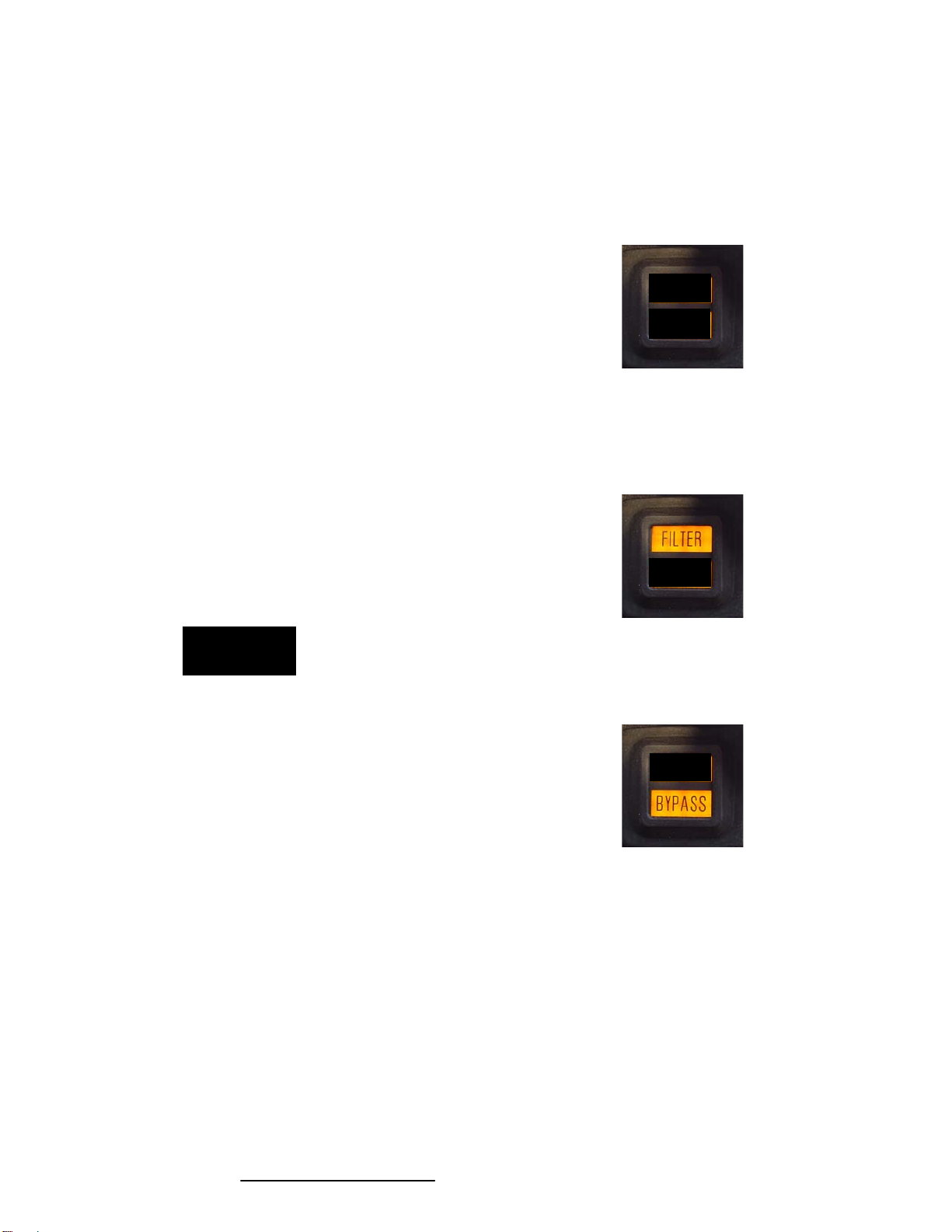
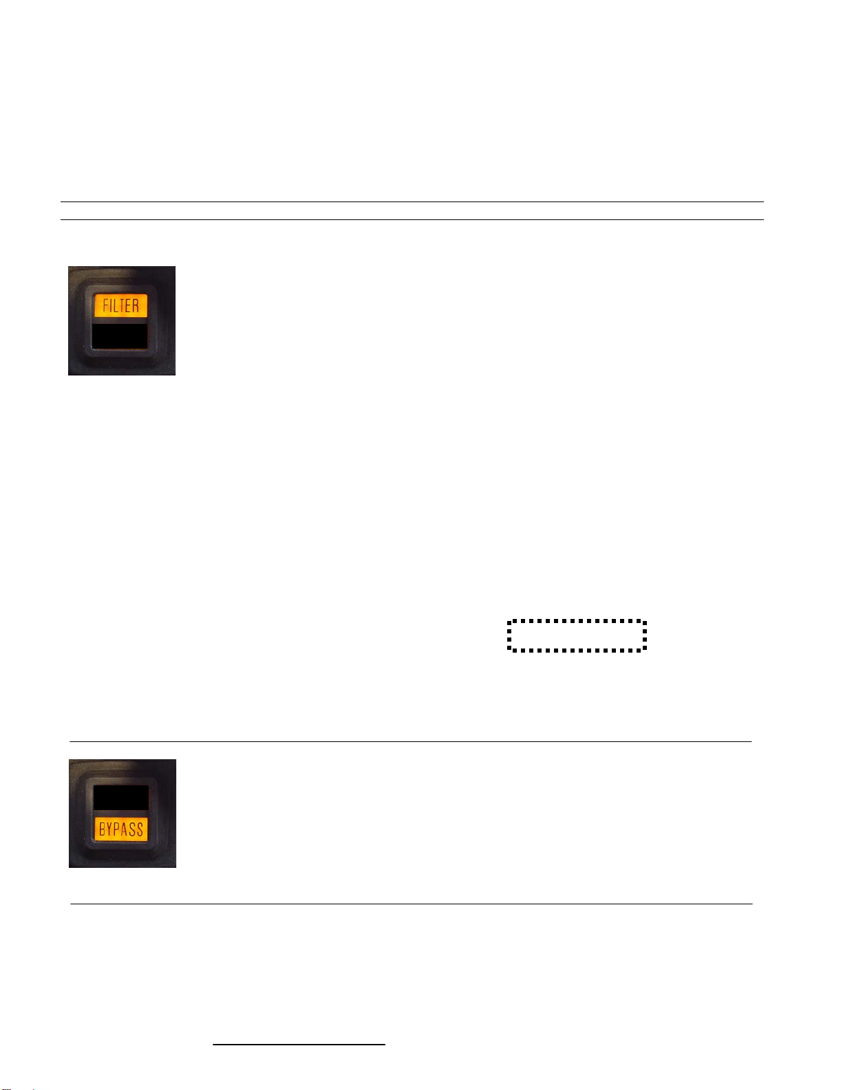
NOTE
Ensure that the IBF “FILTER” and
“BYPASS” caution lights are not
illuminated during performance of the
PAC, and verify that the bypass door is
closed.
The frequency at which the PACs are
conducted is up to the discretion of the
operator and may be based on the current or
forecast operating environment, (i.e.
temperature, altitude, airborne contaminate)
and the requirements of the Flight Manual or
applicable Flight Manual Supplement.
If the engine does not pass PAC, published
performance may not be achieved. Contact
maintenance for appropriate trouble shooting
procedures as outlined in the applicable
Instructions for Continued Airworthiness or
Maintenance Manuals.
AW119 MkII Rotorcraft Only
For AW119 MkII rotorcraft, use of the Basic
PAC charts/procedures, found in Section 4 of
the RFM and the following performance charts
of this RFM Supplement are required.
If the PAC is satisfactory (i.e. the recorded ITT
or N1 values are less than the maximum
allowable values) then EAPS performance can
be obtained and the following performance
data charts are applicable.
If the PAC is not satisfactory then clean the
filters and conduct another PAC. If the new
PAC is found to be satisfactory, then EAPS
performance can be obtained and the following
performance data charts are applicable.
If the recorded PAC results after cleaning the
filters are still not satisfactory (i.e. the recorded
ITT or N1 values are greater than the
maximum allowable EAPS chart values), then
contact maintenance for troubleshooting.
.
C
A
U
TI
O
N

Aerospace Filtration Systems RFM Supplement For
17891 Chesterfield Airport Road Agusta A119 & AW119MKII
Chesterfield, MO 63005 Rotorcraft
AFS-AA119EASA-IBF-FMS Page 10 of 35
EASA Approval Date: Rev.: IR
PERFORMANCE CHARTS
TABLE OF CONTENTS
FIGURE DESCRIPTION PAGE
1
HOVER IGE – TOP
11
2
HOVER IGE – MCP
12
3
HOVER OGE – TOP
13
4
HOVER OGE – MCP
14
5
HOVER OGE – TOP – (CARGO HOOK)
15
6
HOVER OGE – MCP – (CARGO HOOK)
16
7
ROC – TOP 2050 Kg (4519 lb)
17
8
ROC – TOP 2250 Kg (4960 lb)
18
9
ROC – TOP 2450 Kg (5401 lb)
19
10
ROC – TOP 2650 Kg (5842 lb)
20
11
ROC – TOP 2850 Kg (6283 lb)
21
12
ROC – TOP 3000 Kg (6613 lb)
22
13
ROC – TOP 3150 Kg (6944 lb) – (CARGO HOOK)
23
14
ROC – MCP 2050 Kg (4519 lb)
24
15
ROC – MCP 2250 Kg (4960 lb)
25
16
ROC – MCP 2450 Kg (5401 lb)
26
17
ROC – MCP 2650 Kg (5842 lb)
27
18
ROC – MCP 2850 Kg (6283 lb)
28
19
ROC – MCP 3000 Kg (6613 lb)
29
20
ROC – MCP 3150 Kg (6944 lb) – (CARGO HOOK)
30
NOTE: ALL CHARTS – EAPS OFF

Aerospace Filtration Systems RFM Supplement For
17891 Chesterfield Airport Road Agusta A119 & AW119MKII
Chesterfield, MO 63005 Rotorcraft
AFS-AA119EASA-IBF-FMS Page 11 of 35
EASA Approval Date: Rev.: IR
FIGURE 1
ROTOR SPEED: 102 %
ELECTRICAL LOAD: 100 A TOTAL
WHEEL HEIGHT: IGE 3 ft
ZERO WIND
EAPS OFF
HOVER CEILING IN GROUND EFFECT
TAKE-OFF POWER
GROSS WEIGHT {lb x 100}
38 40 42 44 46 48 50 52 54 56 58 60 62
44
42
40
38
36
34
32
30
28
26
24
22
20
18
16
14
12
10
8
6
4
2
0
-
2
PRESSURE ALTITUDE [m x 100]
PRESSURE ALTITUDE [ft x 1000]
15
14
13
12
11
10
9
8
7
6
5
4
3
2
1
0
-1

Aerospace Filtration Systems RFM Supplement For
17891 Chesterfield Airport Road Agusta A119 & AW119MKII
Chesterfield, MO 63005 Rotorcraft
AFS-AA119EASA-IBF-FMS Page 12 of 35
EASA Approval Date: Rev.: IR
FIGURE 2
ROTOR SPEED: 102 %
ELECTRICAL LOAD: 100 A TOTAL
WHEEL HEIGHT: IGE 3 ft
ZERO WIND
EAPS OFF
HOVER CEILING IN GROUND EFFECT
MAXIMUM CONTINUOUS POWER
GROSS WEIGHT {lb x 100}
38 40 42 44 46 48 50 52 54 56 58 60 62
PRESSURE ALTITUDE [ft x 1000]
15
14
13
12
11
10
9
8
7
6
5
4
3
2
1
0
-1
PRESSURE ALTITUDE [m x 100]
44
42
40
38
36
34
32
30
28
26
24
22
20
18
16
14
12
10
8
6
4
2
0
-
2

Aerospace Filtration Systems RFM Supplement For
17891 Chesterfield Airport Road Agusta A119 & AW119MKII
Chesterfield, MO 63005 Rotorcraft
AFS-AA119EASA-IBF-FMS Page 13 of 35
EASA Approval Date: Rev.: IR
FIGURE 3
ROTOR SPEED: 102 %
ELECTRICAL LOAD: 100 A TOTAL
WHEEL HEIGHT: OGE 60 ft
ZERO WIND
EAPS OFF HOVER CEILING OUT OF GROUND EFFECT
TAKE-OFF POWER
GROSS WEIGHT {lb x 100}
38 40 42 44 46 48 50 52 54 56 58 60 62
15
14
13
12
11
10
9
8
7
6
5
4
3
2
1
0
-1
44
42
40
38
36
34
32
30
28
26
24
22
20
18
16
14
12
10
8
6
4
2
0
-2
PRESSURE ALTITUDE [ft x 1000]
PRESSURE ALTITUDE [m x 100]

Aerospace Filtration Systems RFM Supplement For
17891 Chesterfield Airport Road Agusta A119 & AW119MKII
Chesterfield, MO 63005 Rotorcraft
AFS-AA119EASA-IBF-FMS Page 14 of 35
EASA Approval Date: Rev.: IR
FIGURE 4
ROTOR SPEED: 102 %
ELECTRICAL LOAD: 100 A TOTAL
WHEEL HEIGHT: OGE 60 ft
ZERO WIND
EAPS OFF HOVER CEILING OUT OF GROUND EFFECT
MAXIMUM CONTINUOUS POWER
GROSS WEIGHT {lb x 100}
38 40 42 44 46 48 50 52 54 56 58 60 62
15
14
13
12
11
10
9
8
7
6
5
4
3
2
1
0
-1
PRESSURE ALTITUDE [ft x 1000]
44
42
40
38
36
34
32
30
28
26
24
22
20
18
16
14
12
10
8
6
4
2
0
-2
PRESSURE ALTITUDE [m x 100]

Aerospace Filtration Systems RFM Supplement For
17891 Chesterfield Airport Road Agusta A119 & AW119MKII
Chesterfield, MO 63005 Rotorcraft
AFS-AA119EASA-IBF-FMS Page 15 of 35
EASA Approval Date: Rev.: IR
FIGURE 5
ROTOR SPEED: 102 %
ELECTRICAL LOAD: 100 A TOTAL
WHEEL HEIGHT: OGE 60 ft
ZERO WIND
EAPS OFF HOVER CEILING OUT OF GROUND EFFECT
TAKE-OFF POWER
(
CARGO HOOK
)
GROSS WEIGHT {lb x 100}
38 40 42 44 46 48 50 52 54 56 58 60 62 64 66 68 70
15
14
13
12
11
10
9
8
7
6
5
4
3
2
1
0
-1
44
42
40
38
36
34
32
30
28
26
24
22
20
18
16
14
12
10
8
6
4
2
0
-2
PRESSURE ALTITUDE [ft x 1000]
PRESSURE ALTITUDE [m x 100]

Aerospace Filtration Systems RFM Supplement For
17891 Chesterfield Airport Road Agusta A119 & AW119MKII
Chesterfield, MO 63005 Rotorcraft
AFS-AA119EASA-IBF-FMS Page 16 of 35
EASA Approval Date: Rev.: IR
FIGURE 6
ROTOR SPEED: 102 %
ELECTRICAL LOAD: 100 A TOTAL
WHEEL HEIGHT: OGE 60 ft
ZERO WIND
EAPS OFF HOVER CEILING OUT OF GROUND EFFECT
MAXIMUM CONTINUOUS POWER
(
CARGO HOOK
)
GROSS WEIGHT {lb x 100}
38 40 42 44 46 48 50 52 54 56 58 60 62 64 66 68 70
44
42
40
38
36
34
32
30
28
26
24
22
20
18
16
14
12
10
8
6
4
2
0
-2
15
14
13
12
11
10
9
8
7
6
5
4
3
2
1
0
-1
PRESSURE ALTITUDE [ft x 1000]
PRESSURE ALTITUDE [m x 100]

Aerospace Filtration Systems RFM Supplement For
17891 Chesterfield Airport Road Agusta A119 & AW119MKII
Chesterfield, MO 63005 Rotorcraft
AFS-AA119EASA-IBF-FMS Page 17 of 35
EASA Approval Date: Rev.: IR
FIGURE 7
15
14
13
12
11
10
9
8
7
6
5
4
3
2
1
0
-1
ROTOR SPEED: 102 %
ELECTRICAL LOAD: 100 A TOTAL
Vy: 60 KIAS
EAPS OFF RATE OF CLIMB
TAKE-OFF POWER
RATE OF CLIMB {m/s}
0 1 2 3 4 5 6 7 8 9 10 11 12 13 14
44
42
40
38
36
34
32
30
28
26
24
22
20
18
16
14
12
10
8
6
4
2
0
-2
PRESSURE ALTITUDE [ft x 1000]
PRESSURE ALTITUDE [m x 100]

Aerospace Filtration Systems RFM Supplement For
17891 Chesterfield Airport Road Agusta A119 & AW119MKII
Chesterfield, MO 63005 Rotorcraft
AFS-AA119EASA-IBF-FMS Page 18 of 35
EASA Approval Date: Rev.: IR
FIGURE 8
ROTOR SPEED: 102 %
ELECTRICAL LOAD: 100 A TOTAL
Vy: 60 KIAS
EAPS OFF RATE OF CLIMB
TAKE-OFF POWER
RATE OF CLIMB {m/s}
0 1 2 3 4 5 6 7 8 9 10 11 12 13 14
44
42
40
38
36
34
32
30
28
26
24
22
20
18
16
14
12
10
8
6
4
2
0
-2
PRESSURE ALTITUDE [m x 100]
15
14
13
12
11
10
9
8
7
6
5
4
3
2
1
0
-1
PRESSURE ALTITUDE [ft x 1000]

Aerospace Filtration Systems RFM Supplement For
17891 Chesterfield Airport Road Agusta A119 & AW119MKII
Chesterfield, MO 63005 Rotorcraft
AFS-AA119EASA-IBF-FMS Page 19 of 35
EASA Approval Date: Rev.: IR
FIGURE 9
44
42
40
38
36
34
32
30
28
26
24
22
20
18
16
14
12
10
8
6
4
2
0
-2
PRESSURE ALTITUDE [ft x 1000]
15
14
13
12
11
10
9
8
7
6
5
4
3
2
1
0
-1
PRESSURE ALTITUDE [m x 100]
ROTOR SPEED: 102 %
ELECTRICAL LOAD: 100 A TOTAL
Vy: 60 KIAS
EAPS OFF RATE OF CLIMB
TAKE-OFF POWER
RATE OF CLIMB {m/s}
0 1 2 3 4 5 6 7 8 9 10 11 12 13 14

Aerospace Filtration Systems RFM Supplement For
17891 Chesterfield Airport Road Agusta A119 & AW119MKII
Chesterfield, MO 63005 Rotorcraft
AFS-AA119EASA-IBF-FMS Page 20 of 35
EASA Approval Date: Rev.: IR
FIGURE 10
15
14
13
12
11
10
9
8
7
6
5
4
3
2
1
0
-1
PRESSURE ALTITUDE [ft x 1000]
RATE OF CLIMB {m/s}
0 1 2 3 4 5 6 7 8 9 10 11 12 13 14
0 2 4 6 8 10 12 14 16 18 20 22 24 26 28
RATE OF CLIMB {ft/min x 100}
44
42
40
38
36
34
32
30
28
26
24
22
20
18
16
14
12
10
8
6
4
2
0
-2
PRESSURE ALTITUDE [m x 100]
ROTOR SPEED: 102 %
ELECTRICAL LOAD: 100 A TOTAL
Vy: 60 KIAS
EAPS OFF RATE OF CLIMB
TAKE-OFF POWER
PRESSURE ALTITUDE [ft x 1000]
This manual suits for next models
1
Table of contents
Other Donaldson Industrial Equipment manuals

Donaldson
Donaldson X900133 User manual

Donaldson
Donaldson BOFA AD 350 User manual

Donaldson
Donaldson Torit MediaFilter Horizontal Series User manual

Donaldson
Donaldson Torit AIRPLUS Trunk 2000 T-2000 User manual

Donaldson
Donaldson BOFA AD 1000 iQ User manual

Donaldson
Donaldson Ultra-Filter DF 0035 User manual

Donaldson
Donaldson Torit RVS-5 User manual