Wilbur Curtis Company TP1T User manual

1
Models Included
•TP1T
•TP1TT
•TP1S
•TP1ST
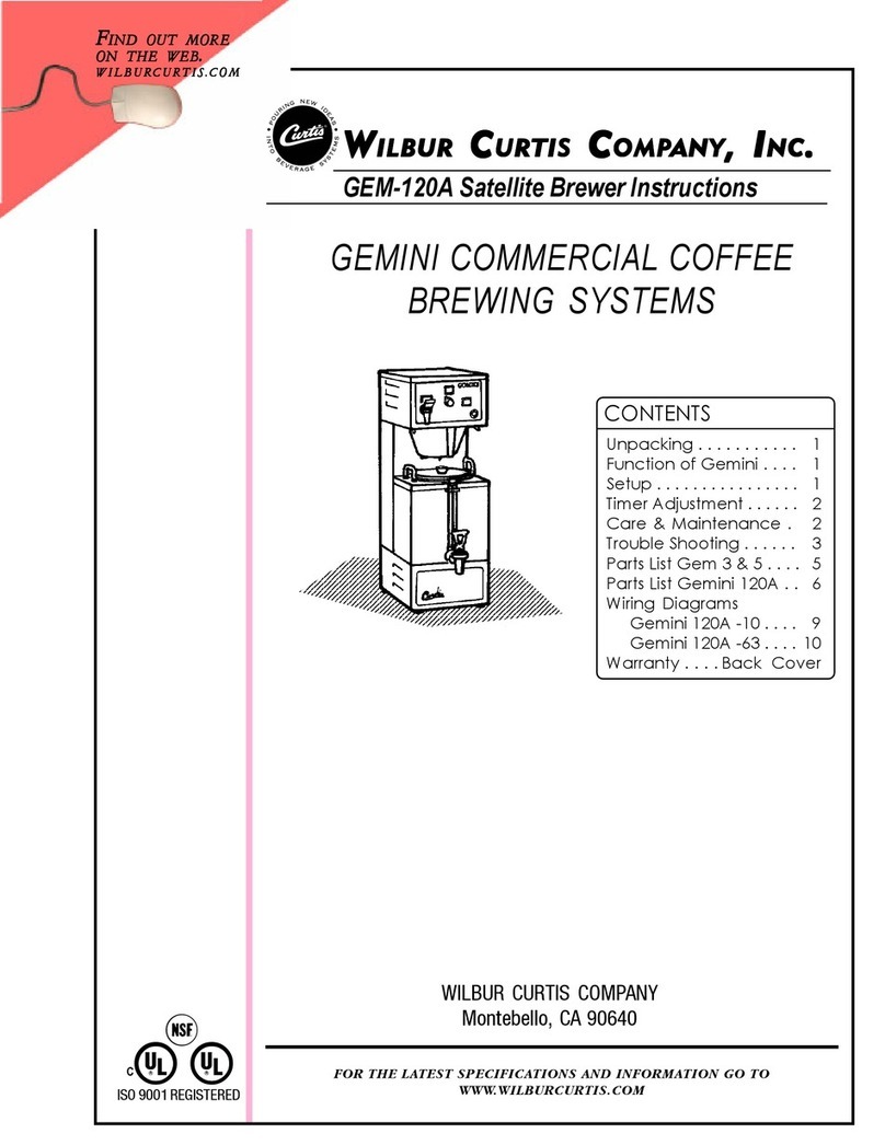
This equipment is designed for commercial use. Any servicing other than cleaning and routine maintenance
should be performed by an authorized Wilbur Curtis Company Service Technician.
• DONOTimmersetheunitinwateroranyotherliquid
• Toreducetheriskofreorelectricshock,DONOTopenservicepanels.Therearenouser
serviceable parts inside.
• Keephandsandotheritemsawayfromhotareasoftheunitduringoperation.
• Nevercleanwithscouringpowdersorharshchemicals.
Important Safeguards/Symbols
ServiceManual,1GallonBrewers
Wilbur Curtis Company, inC.
Symbols:
WARNINGS – To help avoid personal injury
Important Notes/Cautions – from the factory
Sanitation Requirements
Installation
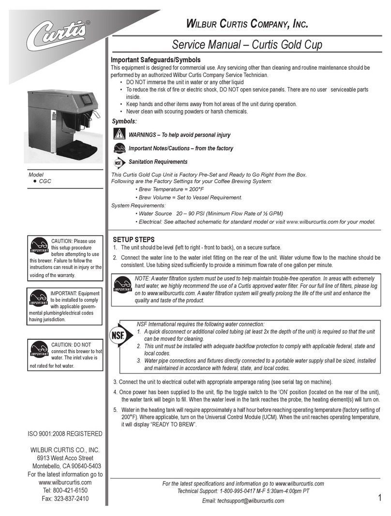
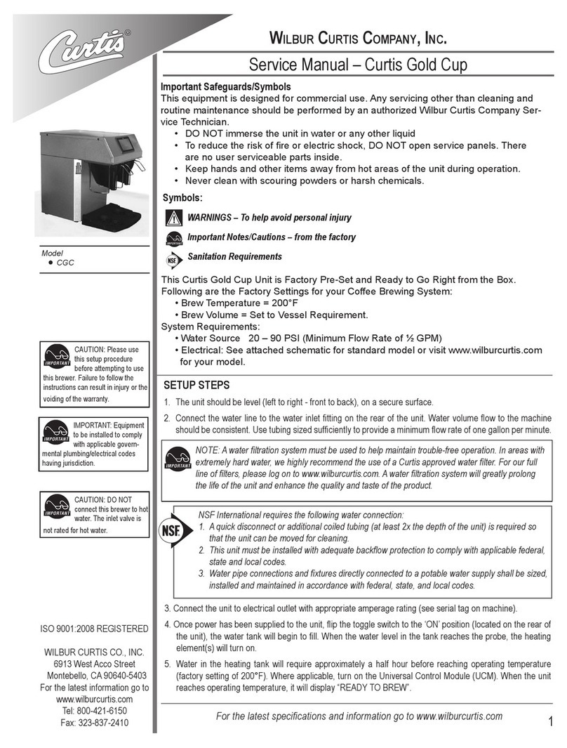
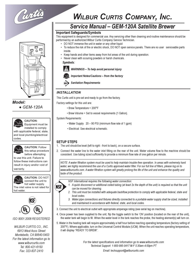
This Curtis unit is pre-set and ready to go from the factory.
Factory settings for this unit are:
•BrewTemperature=200°F
•WaterBypass=OnLARGE&MEDIUMbrewonly
•BrewVolume=Settovesselrequirements(specicbasedonmodel).
SystemRequirements:
•WaterSupply20–90PSI(minimumowrateof1gpm)
•Electrical:Seeelectricalschematic.
3.Connecttheunittoelectricaloutletwithappropriateamperagerating(seeserialtagonmachine).
4.Oncepowerhasbeensuppliedtotheunit,ipthetoggleswitchtothe‘ON’position(locatedontherearof
theunit),thewatertankwillbegintoll.Whenthewaterlevelinthetankreachestheprobe,theheating
element(s)willturnon.
5.Waterintheheatingtankwillrequireapproximatelyahalfhourbeforereachingoperatingtemperature(factory
settingof200°F).Whereapplicable,turnontheUniversalControlModule(UCM).Whentheunitreaches
operatingtemperature,itwilldisplay“READYTOBREW”.
NSFInternationalrequiresthefollowingwaterconnection:
1. Aquickdisconnectoradditionalcoiledtubing(atleast2xthedepthoftheunit)isrequiredsothatthe
unit can be moved for cleaning.
2. Thisunitmustbeinstalledwithadequatebackowprotectiontocomplywithapplicablefederal,state
and local codes.
3.Waterpipeconnectionsandxturesdirectlyconnectedtoaportablewatersupplyshallbesized,
installedandmaintainedinaccordancewithfederal,state,andlocalcodes.
NOTE:Awaterltrationsystemmustbeusedtohelpmaintaintrouble-freeoperation.Inareaswith
extremelyhardwater,wehighlyrecommendtheuseofaCurtisapprovedwaterlter.Forourfulllineof
lters,pleaselogontowww.wilburcurtis.com.Awaterltrationsystemwillgreatlyprolongthelifeofthe
unit and enhance the quality and taste of the product.
Setup Steps
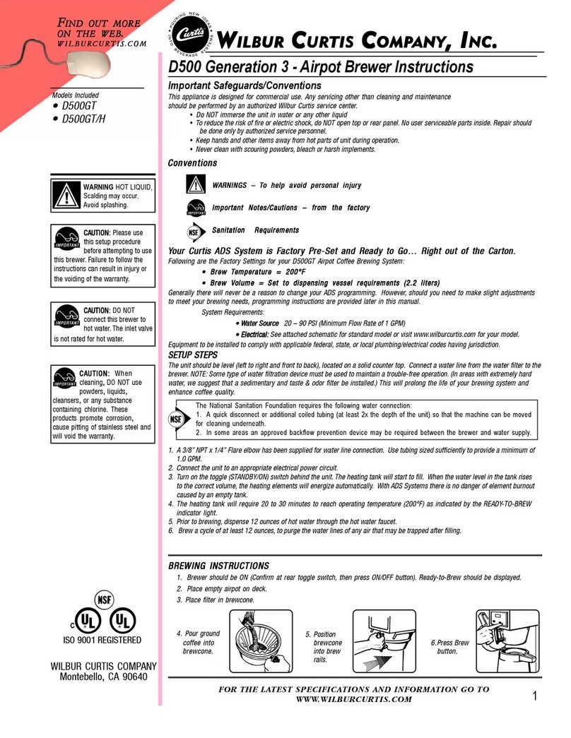
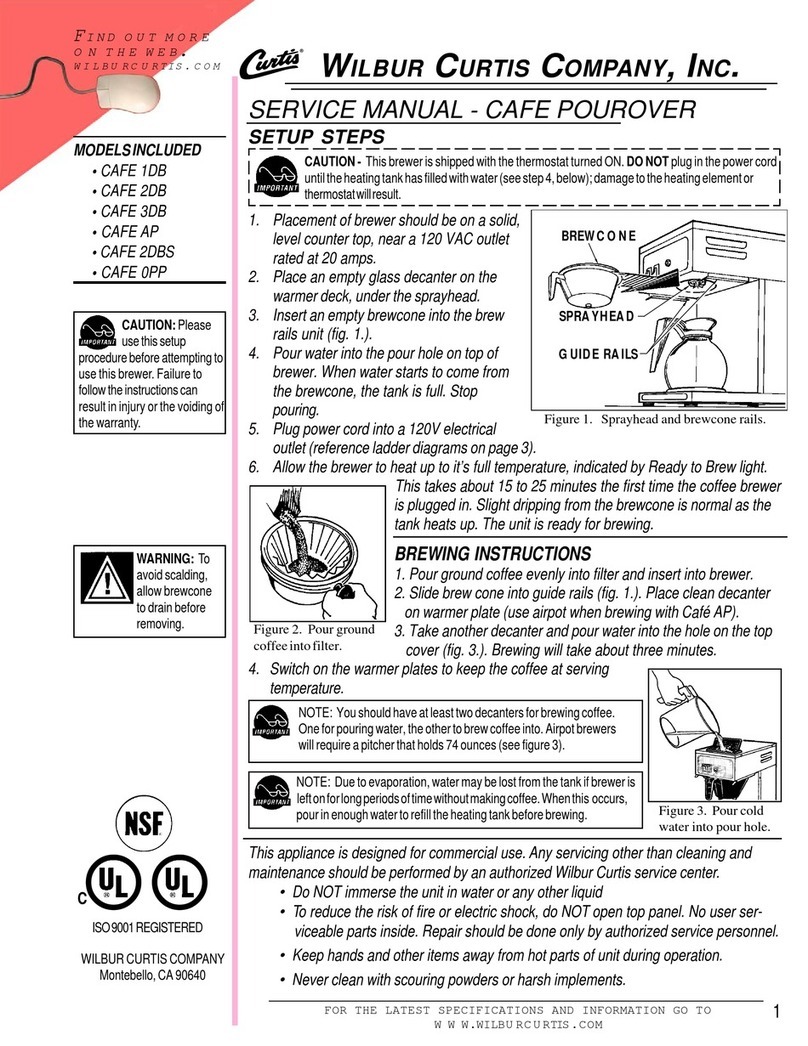
1.Theunitshouldbelevel(lefttoright-fronttoback),onasecuresurface.
2. Connectthewaterlinetothewaterinletttingontherearoftheunit.Watervolumeowtothemachine
shouldbeconsistent.Usetubingsizedsufcientlytoprovideaminimumowrateofonegallonperminute.
CAUTION: DONOT
connect the unit to
hot water supply.
Theinletvalveisnotratedfor
hot water.
CAUTION: Follow
this setup procedure
beforeattempting
to use this unit. Failure to
followtheseinstructionscan
resultininjuryand/orvoidof
warranty.
ISO 9001:2008 REGISTERED
WILBUR CURTIS CO., INC.
6913 West Acco Street
Montebello, CA 90640-5403
For the latest information go to
www.wilburcurtis.com
Tel: 800-421-6150
Fax: 323-837-2410
CAUTION:
Equipmentmustbe
installedtocomply
withapplicablefederal,state,
andlocalplumbing/electrical
codes.
FOR THE LATEST SPECIFICATION INFORMATION GO TO WWW.WILBURCURTIS.COM

2
POUR COFFEE INTO
BASKET
INSERT BREWCONE INTO
RAILS
BREWING INSTRUCTIONS
UseonlycoffeeorwaterintheThermoProdispenser.Donotusetheservertodispenseanyotherbeverage.Preheat-
ingtheserverwithhotwaterisrecommended.Thesingleheadbrewerisshowbelow,thetwinheadbrewerissimilar.
1. Placeacleanandemptyserveronthedeck.Servershouldbecenteredbelowthebrewconeofthebrewer.
2. MakesuretheunitisuptobrewingtemperatureandtheLCDscreenreadsREADYTOBREW.
3. Placealterinthebrewconeandpourinthecorrectmeasureofgroundcoffeeforthebrewvolume.
4. Slidethebrewconeintothebrewrails.
5. Selectandpressdesiredbrewbutton(LARGEorSMALL).Theunitwillstartthebrewcycle.
6. Allowcoffeeinthebrewconetodripoutcompletelybeforeremovingtheinsulatedserver.
WARNING–THERMOPROSERVERSMAYBEHEAVYWHENFILLED.
CAREMUSTBETAKENWHENTRANSPORTINGTOAVOIDDROPPINGORSPILLING.
PRESS THE BREW BUTTON

3
T-Pro Short
Twin
T-Pro Short
Single
IMPORTANT NOTE:
All programming selections are performed with the three center buttons.
The symbols below the buttons are:
Scroll LEFT
SELECTION or ENTER to save new parameter
Scroll RIGHT
Tank Temperature Check
To check the temperature of the water within the heating tank, make sure brewer is on and Ready to Brew is displayed. Press and hold the
button (see illustration, page two) for 5 seconds. The water temperature inside the tank will be displayed.
Control Module Menu Tree
TheowchartdisplaysthesequenceofmenuitemthatcanbeaccessedthroughtheUCM.Variousmenuitemswillimmediatelyexitthepro-
grammingmodewhenselected.Othermenuitems,whenselected,willcontinuetothenextiteminthemenulist.

4
30
21
31
1
2
5
3
4
6
7
8
9
10
35
11
12
13
14
15
16
18
19
20
17
27
24
25
26
27
28
32
33
34
22
23
29
PARTS DIAGRAMS
Twin 1 Gallon Brewer

5
PARTS LIST
TP1T & TP1TT
1
2
3
4
5
6
7
7A
8
9
9A
10
11
12
13
14
15
16
17
18
19
20
21
22
23
24
25
26
27
28
29
30
31
32
33
34
35
WC-5421
WC-37121*
WC-2977-101K
WC-4212-02*
WC-37122*
WC-37231*
WC-1809
WC-1806*
WC-29050
WC-59022
WC-61612
WC-8559
WC-3417
WC-2402P
WC-847*
WC-102*
WC-8591*
WC-3518
WC-3503
WC-37008*
WC-43067*
WC-62033
WC-5502-01*
WC-37317
WC-37357
WC-4382
WC-522*
WC-43055
WC-37266
WC-1438-101*
WC-934-04*
WC-5231*
WC-5310*
WC-37132*
WC-3765L*
WC-844-101*
GEM-6
COVER,TOP
VALVE,LIQUIDDISPENSINGLEFT120VAC
KIT,SPRAYHEADFITTINGULTEM
NUT,5/8-18JAMULTEM
VALVE,DUMP120V12WRIGHT
KIT,UCM&LABELTPS1T/TP1TT
FAUCET,HOTWATERW/JAMNUT
SEATCUP,FORWC-1809(NOTSHOWN)
SPRAYHEAD,AMBERADVANCEDFLOW
PANEL,FRONTTPS1T
PANEL,FRONTTP1TT
RELAY,SOLIDSTATE40AW/HEATSINK
BREWCONE,ASSYW/SPLASHPOCKETBRNCOFFEE
ELBOW,3/8”FLx3/8”NPTPLATED
VALVE,INLET2GPM
SWITCH,TOGGLE125/250VACRESISTIVE
CAPACITOR,X2
LEG,GLIDE3/8-16STUDSCREW
LEG,3/8-16STUDSCREW(NON-GLIDE)
KIT,HEATINGTANKLID
GASKET,TANKLID
TANK,COMPLETEGEMTSW/ULTEMFTTNGS
KIT,PROBEASSYWATERLEVELW/O-RING&NUT
KIT,STRAIGHTFITTING&BUSHNGGENUSE
KIT,STRAIGHTPLASTICFITTINGANDBUSHING12MM
GUARD,SHOCKHEATINGELEMENT
THERMOSTAT,HILIMITHTRDPST277V40A
GUARD,SHOCKRESETTHERMOSTAT
KIT,FITTINGTANKOVERFLOW
SENSOR,HEATINGTANK
ELEMENT,HEATING2.5KW220V
COMPOUND,SILICONE5OZTUBE
TUBING,SILICONE,5/16”I.D.(1FT.)
KIT,VALVEREPAIRUSEONWC-820WDR,WC-821WDR
KIT,VALVEREPAIRUSEONWC-847
VALVE,BY-PASS120VNON-ADJW/RSTRCTR
FILTER,500/PKG12½x4
ITEM № PART № DESCRIPTION
*RECOMMENDEDPARTSTOSTOCK.

6
22
23
24
1
2
3
4
5
6
7
17
18
19
20
21
8
9
10
11
34
12
13
33
14
15
16
25
26
27
28
32
31
35
30
29
PARTS DIAGRAMS
TP1S & TP1ST

7
PARTS LIST TP1S & TP1ST
1
2
3
4
5
6
7
8
8A
9
9A
10
11
12
13
14
15
16
17
18
19
20
21
22
23
24
25
26
27
28
29
29A
30
31
32
33
34
35
WC-58117
WC-37266
WC-5502-01*
WC-37317
WC-4394
WC-43055
WC-1438-101*
WC-61556
WC-61556-101
WC-43068*
WC-43068-101*
WC-62037
WC-37357
WC-904-04*
WC-522*
WC-844-01*
WC-37122*
WC-2977-101K
WC-8559
WC-37287*
WC-39580
WC-38439
WC-1809
WC-102*
WC-8591*
WC-847*
WC-29050
WC-2402P
WC-3518
WC-3503
WC-61622
WC-61551
WC-3417
WC-3765L*
WC-37132*
WC-5231*
WC-5310*
GEM-6*
COVER,TOP
KIT,FITTINGTANKOVERFLOW
KIT,PROBEASSYWATERLEVELW/O-RING&NUT
KIT,STRAIGHTFITTING&BUSHNGGENUSE
GUARD,SHOCKHEATINGELEMENT
GUARD,SHOCKRESETTHERMOSTAT
SENSOR,HEATINGTANK
COVER,TANK(FORUNITSMADEBEFORE1/2010)
LID,TANKTP1S
GASKET,TANKLID(UNITSMADEBEFORE1/10)
GASKET,TANKLIDRECTANGULARTP1S
TANKCOMPLETETP1S/TP1ST
KIT,STRAIGHTPLASTICFITTINGANDBUSHING12MM
ELEMENT,HEATING1.6KW120VW/JAMNUT
THERMOSTAT,HILIMITHTRDPST277V40A
VALVE,BY-PASS,NON-ADJUSTABLEW/RSTRCTR
KIT,DUMPVALVERIGHT
KIT,SPRAYHEADFITTINGULTEM
RELAY,SOLIDSTATE40AW/HEATSINK
KIT,UCM&OVERLAY2-BATCHTP1S
LABEL,UCMOVERLAY2-BATCH
LABEL,FRONTHOTWATER
FAUCET,HOTWATERW/JAMNUT
SWITCH,TOGGLE125/250VACRESISTIVE
CAPACITOR,X2
VALVE,INLET2GPM
SPRAYHEAD,AMBERADVANCEDFLOW
ELBOW,3/8”FLx3/8”NPTPLATED
LEG,GLIDE3/8-16STUDSCREW
LEG,3/8-16STUDSCREW(NON-GLIDE)
COVER,FRONTSSTP1STTALL
COVER,FRONTSSTP1SSHORT
BREWCONE,ASSYW/SPLASHPOCKETBRNCOFFEE
KIT,VALVEREPAIRUSEONWC-847
KIT,VALVEREPAIRUSEONWC-844WDR/WC-821WDR
COMPOUND,SILICONE5OZTUBE
TUBING,SILICONE,5/16”I.D.
FILTER,500/PKG12½x4
ITEM № PART № DESCRIPTION
*RECOMMENDEDPARTSTOSTOCK.

8
CAUTION
Donotimmerseserverinwater.
Donotplaceinserverdishwasher.
Donotuseharshpowdersorcleanserscontainingchlorine.
Do not use a wire brush or pot scourer to clean inside liner.
Cleaning and Sanitizing Instructions for TLXG01 Server
Thesecleaningandsanitizinginstructionsareonlyaguidelinetobeusedforthecleaningandsanitizing
oftheTLXG01.Yourcurrentin-housecleaningandsanitizingmethodsmaybejustaseffective.
ForcleaningandsanitizingoftheTLXG01,thethreesinkmethodisrecommended.Thismethodconsists
ofasinkofwaterlledwithadetergentandwatersolution,afreshwaterrinse,andasinklledwithan
aqueoussanitizingsolution.ImmersepartsincommercialBarTabs/Sani-Tabssanitizingsolution.Thesolu-
tionmustbewarm(75°F.)Letthepartssoakatleastoneminute.
CLEANING
Regularcleaningofthecoffeebrewerwillmaintainthehighestqualitycoffeeyourequipmentiscapableofproducing.Proper
cleaningisessentialtomaintainafreshandappealinglooktoyourcoffeeservice.Tocleanthecoffeebrewercomponents,prepare
amildsolutionofdetergentandwarmwater.
1. FirstturnoffthebrewerusingtheON/OFFbuttononthefrontcontrolpanel.
2. Wipeallexteriorsurfaceswithadampcloth,removingspillsanddebris.
3. Slidethebrewconeoutandcleanit.Thoroughlywipesprayheadareawithadampcloth.
4. Washthebrewcone.Useasoftbristledbrushforhardtocleanareas.Washbothpartswithadetergentsolutionorputthese
parts through a dishwasher.
CAUTION
Donotuseharshpowdersorcleanserscontainingchlorine.
1. Daily, Rinse the unit after use.
a. Openunitandemptycontentscompletely.
b. Rinseunitwithhotwater,thenopenfaucettodrain.
c. Wipeoutsideofunitwithcleanclothmoistenedwithcleaningsolution.
2. Cleaning and server assembly.
a. Filltheunitwithcleaningsolution.Withaspongebrush,thoroughlycleaninsideliner.
b. Rinsetheunitusingafreshwaterrinse.
3. Clean and sanitize the lid assembly.
a. Removelidfromunitandsubmerseitincleaningsolution,cleaningthoroughly.
b. Usingthesuppliedbrush,cleaninsidethellingtube.
c. Rinsewithcleanwater.
d. Tosanitize,submerseinsanitizingsolutionfor5minutesthenairdrycompletely.
4. Cleaning the faucet and gauge glass.
a. Unscrewthebonnet/handleassemblyfromthefaucet.
b. Removegaugeglassfromunitandbrushoutwithcleaningsolution.
c. Withthefaucetremoved,cleanthesiliconeelbowtting(TanktoFaucetTube).Usethetubebrushsoakedincleaning
solution,insertedthroughthefaucetshank.
d. Cleanandrinseparts.
e. Tosanitize,placeinsanitizingsolutionfor5minutes,removeandairdry.
5. Sanitizing the assembled TLXG01 server.
a. Fillacleanserverwithsanitizingsolution.Allowtositfor5minutesthendrainthroughthefaucet.
b. Placebodyassemblyupsidedownonracktothoroughlyairdry.

9
27.875"
(70.8 cm)
36.625"
(93.0 cm)
9.25"
(23.5 cm)
20.750"
(52.7 cm)
20.250"
(51.4 cm)
29.500"
(74.9 cm) 24.625"
(62.5 cm)
16.125"
(41.0 cm)
16.500"
(41.9 cm)
16.625"
(42.2 cm)
ROUGH-IN DRAWING
TP1S & TP1ST
ROUGH-IN DRAWING
TP1T & TP1TT

10
ELECTRICAL SCHEMATIC
TP1T & TP1TT

11
ELECTRICAL SCHEMATIC
TP1S & TP1ST

12
10/11/[email protected] 14475.revE
4/1/1[email protected]_revD
12/9/8 . 10.7 . ECN 10134 revC
1/18/8 . 12.8 . ecn 9443
1/25/07 . 13.7 . ecn 8745
Printed in U.S.A. 10/2012 F-3484 Rev E
WILBUR CURTIS CO., INC.
6913 Acco St., Montebello, CA 90640-5403 USA
Phone: 800/421-6150 Fax: 323-837-2410
Technical Support Phone: 800/995-0417 (M-F 5:30A - 4:00P PST) E-Mail: [email protected]
Web Site: www.wilburcurtis.com
ProductWarrantyInformation
TheWilburCurtisCompanycertiesthatitsproductsarefreefromdefectsinmaterialandworkmanshipundernormaluse.Thefol-
lowinglimitedwarrantiesandconditionsapply:
3Years,PartsandLabor,fromOriginalDateofPurchaseondigitalcontrolboards.
2 Years,Parts,fromOriginalDateofPurchaseonallotherelectricalcomponents,ttingsandtubing.
1Year,Labor,fromOriginalDateofPurchaseonallelectricalcomponents,ttingsandtubing.
Additionally,theWilburCurtisCompanywarrantsitsGrindingBurrsforForty(40)monthsfromdateofpurchaseor40,000pounds
ofcoffee,whichevercomesrst.StainlessSteelcomponentsarewarrantedfortwo(2)yearsfromdateofpurchaseagainstleaking
orpittingandreplacementpartsarewarrantedforninety(90)daysfromdateofpurchaseorfortheremainderofthelimitedwarranty
periodoftheequipmentinwhichthecomponentisinstalled.
Allin-warrantyservicecallsmusthavepriorauthorization.ForAuthorization,calltheTechnicalSupportDepartmentat1-800-995-
0417.EffectivedateofthispolicyisApril1,2003.
Additionalconditionsmayapply.Gotowww.wilburcurtis.comtoviewthefullproductwarrantyinformation.
CONDITIONS&EXCEPTIONS
Thewarrantycoversoriginalequipmentattimeofpurchaseonly.TheWilburCurtisCompany,Inc.,assumesnoresponsibilityfor
substitutereplacementpartsinstalledonCurtisequipmentthathavenotbeenpurchasedfromthe
WilburCurtisCompany,Inc.TheWilburCurtisCompanywillnotacceptanyresponsibilityifthefollowingconditionsarenotmet.The
warrantydoesnotcoverandisvoidunderthefollowingcircumstances:
1) Improperoperationofequipment:Theequipmentmustbeusedforitsdesignedandintendedpurposeandfunction.
2) Improperinstallationofequipment:Thisequipmentmustbeinstalledbyaprofessionaltechnicianandmustcomplywithall
localelectrical,mechanicalandplumbingcodes.
3) Impropervoltage:Equipmentmustbeinstalledatthevoltagestatedontheserialplatesuppliedwiththisequipment.
4) Improperwatersupply:Thisincludes,butisnotlimitedto,excessiveorlowwaterpressure,andinadequateoructuating
waterowrate.
5) Adjustmentsandcleaning:Theresettingofsafetythermostatsandcircuitbreakers,programmingandtemperature
adjustmentsaretheresponsibilityoftheequipmentowner.Theownerisresponsibleforpropercleaningandregular
maintenanceofthisequipment.
6) Damagedintransit:Equipmentdamagedintransitistheresponsibilityofthefreightcompanyandaclaimshouldbe
madewiththecarrier.
7) Abuseorneglect(includingfailuretoperiodicallycleanorremovelimeaccumulations):Manufacturerisnotresponsiblefor
variationinequipmentoperationduetoexcessivelimeorlocalwaterconditions.Theequipmentmustbemaintainedaccord-
ingtothemanufacturer’srecommendations.
8) Replacementofitemssubjecttonormaluseandwear:Thisshallinclude,butisnotlimitedto,lightbulbs,sheardisks,“0”
rings,gaskets,siliconetube,canisterassemblies,whipperchambersandplates,mixingbowls,agitationassembliesand
whipper propellers.
9) Repairsand/orReplacementsaresubjecttoourdecisionthattheworkmanshiporpartswerefaultyandthedefectsshowed
upundernormaluse.Alllaborshallbeperformedduringregularworkinghours.Overtimechargesaretheresponsibilityof
theowner.Chargesincurredbydelays,waitingtime,oroperatingrestrictionsthathindertheservicetechnician’sabilityto
performserviceistheresponsibilityoftheowneroftheequipment.Thisincludesinstitutionalandcorrectionalfacilities.
TheWilburCurtisCompanywillallowupto100miles,roundtrip,perin-warrantyservicecall.
RETURNMERCHANDISEAUTHORIZATION:AllclaimsunderthiswarrantymustbesubmittedtotheWilburCurtisCompany
TechnicalSupportDepartmentpriortoperforminganyrepairworkorreturnofthisequipmenttothefactory.Allreturnedequip-
mentmustberepackagedproperlyintheoriginalcarton.Nounitswillbeacceptediftheyaredamagedintransitduetoimproper
packaging.NOUNITSORPARTSWILLBEACCEPTEDWITHOUTARETURNMERCHANDISEAUTHORIZATION(RMA).RMA
NUMBERMUSTBEMARKEDONTHECARTONORSHIPPINGLABEL.Allin-warrantyservicecallsmustbeperformedbyan
authorizedserviceagent.CalltheWilburCurtisTechnicalSupportDepartmenttondanagentnearyou.
FOR THE LATEST SPECIFICATION INFORMATION GO TO WWW.WILBURCURTIS.COM
This manual suits for next models
3
Table of contents
Other Wilbur Curtis Company Coffee Maker manuals

Wilbur Curtis Company
Wilbur Curtis Company CBHS User manual

Wilbur Curtis Company
Wilbur Curtis Company GEM SS User manual
Wilbur Curtis Company
Wilbur Curtis Company CBS User manual

Wilbur Curtis Company
Wilbur Curtis Company Brewer User manual

Wilbur Curtis Company
Wilbur Curtis Company D60GT User manual

Wilbur Curtis Company
Wilbur Curtis Company Gold Cup User manual

Wilbur Curtis Company
Wilbur Curtis Company G4 ThermoPro G4TP2T User manual

Wilbur Curtis Company
Wilbur Curtis Company GEM-120A User manual

Wilbur Curtis Company
Wilbur Curtis Company Curtis CGC User manual

Wilbur Curtis Company
Wilbur Curtis Company TLP10 User manual