Wilcox-Gay 3F10 User manual

H*toroFAcr* FolJ.t
ffi
ffi
RADIO-PHONO
TV
INPUT
RECORDING
INDICATORS
RfVERSE
AC LINE
CORD
RECEPTACLE
RECORD EXTERNAL
SPEAKER JACK
FORWARD VOLUME CONTROL
ON-OFF SWITCH
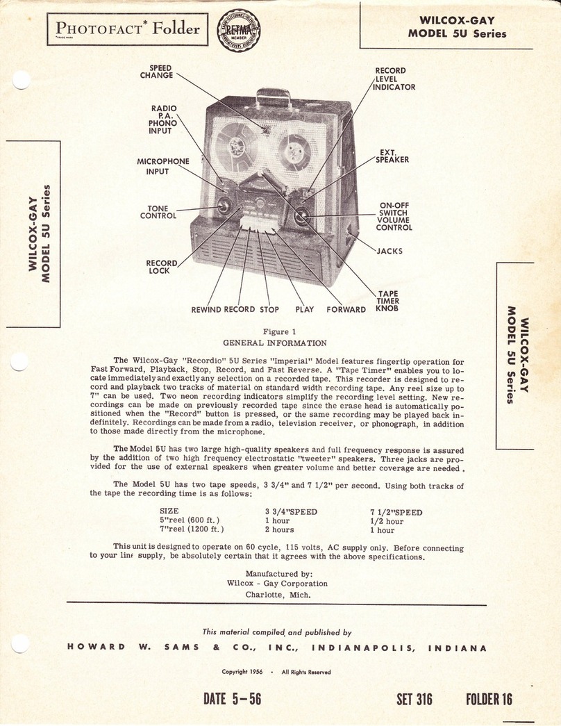
GENERAL INFORMATION
The Wilcox-Gay "Recordio" Model 3FI0 features fingertip operation f or Fast Forward, Play-
back, Stop, Record and Fast Reverse. The "Recordio" is designed to record and play back two
tracks of material on standard width recording tape, which doubles the playing time of a standard
5" or ?" reel of tape with no loss of frequency response or quality. Recordings can be made
from a radio, television receiver or phonograph, in addibion to those made directlyfrom the
rnicrophone. Recordings can be played back through the seU-conbained speaker or an external
speaker through use of the Auxiliary Speaker Jack.
This "Recordio" has two tape speeds, 7 l/2" and 3 3/4" per second. Using both channels of the
tape, the recording time is as follows:
MIKE
lf'{FUT
ie
qs
X-r
8x
ro
==
={
OF
H8
ry
*f,
6l
SIZE
5" reel
?t'reel
SPEED
3-3/ 4
t hour
2 hours
SPEED
7-r/2
1/ 2 hour
t hour
The 3FI0 is designed to operate on 60 cycle, ll5 volt, AC supply.
CAUTION: Severe Damage WiII Result if Connection is Made to a Direct Current (DC) Line.
Manufactured by:
Wilcox-Gay Corporation
Brooklyn, N. Y. Charlotte, Mich.
wttcox-GAY
MODEL 3FIO
fhis moleriol compiled ond published by
SAMS & CO., lNC., INDIANAPOIlS,
Copyright 1953 ' All Rights Reserved
DATT II-5 3
INDIANA
srT 22 0t0tDER ll
HOWARD \/.

./-'-- . /:\
J8)
,:lffi \J
Figure 2.
OPEFATING INSTRUCTIONS
I. With the "Stop" button depressed, insert the
AC power cord into the receptacle at the right side
of the cabinet (Figure I).
2. Plug the AC cord into a convenient wall
receptacle of the proper rating.
Threading the Tape -
I. Place a reel of tape on the left spindte (a)
and an empty reel on the right spindle (8) making
surethe reel slots engagethe reelpin on thespindles.
2. Unwind about 14" of the tape from the reel.
HoId a section of the tape straight with both hands
and insert the tape in the tape slot making sure the
dull coated side of the tape f aces the rear of the
recorder.
NOTE: This recorder u s e s Type "A" wound tape,
i. e. the dull magnetic coated side faces in-
ward on the reel. If the tape to be used is
Type "B" (coated side facing outward) place
the reel on the left spindle so that the tape
will lead-off in a clockwise direction. Bring
the tape behindthe rear cover (5)(not
through the head slot) and thread it on to the
right reel in the normal manner. Press the
"Forward" button and allow the full reel of
tape to wind on the empty reel. The duII
side of the tape wiII now be facing inward on
the reel.
3. Insert the free end of the tape through the
hub of the right take-up reel and place a pencil
firmly over the tape, forcing it into one of the three
Page 2
radial slots on the hub of the empty reel. Turn the
reel several turns with the pencil in this position
until the tape is secured to the reel and all slack is
taken up between the reels.
To Record From Microphone -
I. Turn the On-Off Volume Control to the right
until a click is heard and allow about thirty seconds
for the unit to warm up. The pilot light located
above the "Stop" button will glow when the unit is
turned on.
2. Insert the microphone plug into the "Micro-
phone Input Jack".
3. Turnthe speed control knob(I)to the deslred
speed.
NOTE: Recordings made at a certain speed must be
played back at that speed.
4. Move record lock Iever (18) downward with
the left hand. This releases the record safety lock
which prevents accidental erasure.
5. Depress the "Record" button with the right
hand (while holding the record lock lever (I8) with the
Ieft hand) until it latches.
6. Whiie talking into the microphone, adjust
the "Volumen control until the "Normal" indicator
f.Iashes and no flashing occurs at the "Overload"
indicator.
NOTE: Correct recording volume is very important.
Too weak a signal, which does not cause the
"Normal" indicator to flash, will re sult in
weak playback and high background noise.

fl!%'';.'r.
Figure 3.
Too strong a signal, causing the "Overload" NOTE: Should a hum develop from the above con-
indicator to flash, wiII result in distortion nection, reverse the cord clips on the pick-
during playback. up leads.
To Record From External Radio -To Record From Television Receiver
3{
OF
H8
r;1
H6t
6l
Recordings can be rnade from a radio by placing the
microphone near the loudspeaker of the radio;
howeve r, this type of recording may not be satis-
factory as other sounds may be picked up by the
microphone which as a result wiII be recorded on the
tape. A superior quality recording can be rnade by
use of radio-phono attachment cord (Part No.
C-20.233). Connect attachment cord as follows:
I. Connect the cord clips across the voice coil
terminals on the radio speaker as shown in
Figure 4.
2. Insert the cord plug into the "Radio, TV,
Phono Jack".
3" Proceed as described in "To Record From
Microphone".
NOTE: Remove attachment cord after recording is
completed.
To Record From Phonograph -
I. Connect the cord clips of the attachment
cord to the pickup leads on the external phonograph.
2. Insert the attachment cord plug into the
"Radio, TV, Phono Jack".
3. Proceed as described in "To Record From
Microphone".
I. Connect attachment cordas describedin
"To Record From External Radio" and proceed with
recording as described in "To Record From Micro-
phone".
NOTE: The "Recordio" Tone Control does not oper-
ate during recording. When recording from
radio or a television receiver set the radio
or television tone control for maximum
treble.
DuaI Track Recording -
The Recordio is designed so that L/ 2 the tape width
is recorded at a time; thereby resultingin two
track recording. This two track operationis
accomplished in the following manner:
I. After a reel of tape has been recorded,
i. e. all of the tape wound on to the take-up
reel, depress the I'Stop" push button. This
stops all movement of the tape.
2. Remove the reels from the recorder,
turning the fuII reel over and placing it on the
Ieftspindle andthe empty reel onthe right
spindle.
3. Properly thread the tape and proceed with
the recording as in I'To Record F r o m Micro-
phonett.
Page 3

Figure 4.
4. After this track has been recorded the
f i r s t track of recording is ready to be played
without rewinding.
(a) Place the futl reel of tape on the feed reel
(lef t) spindle and the empty reel on the
take-up (right) spindle.
(b) Thread the tape making sure the duII side
of the tape faces the record head.
(c) Set the controls as described under "To
Play a Recording".
To PIay a Recording -
1. Thread the tape as described under
"Threading the Tape".
2. Turn the On-Off Volume control on and
allow thirty seconds for the tubes to warm up.
3. Depress the "Play" button until it is
Iatched into position.
4. Adjust the Volume and Tone control to suit.
-
Any size speaker of the permanent magnet type,
having a 3 ohm voice coil, may be used by connecting
a speaker extension cord acorss the voice coil of the
speaker and then inserting the extension plug (same
type as micorphone plug) into the External Speaker
Jack located on the r i g h t side of the cabinet. This
automatically cuts out the seU-contained speaker.
To Edit and Splice Tape -
NOTE: Since it is impossible to edit and splice
one track without affecting the other, re-
cordings which a r e to be edited should be
Iimited to one track only.
I. T h e tape may be edited by cutting out un-
wanted portions, or by joining selections into an-
othe r sequence. Announcements m ay be inserted
Page 4
betweenselections, etc. Unused sections of tape
can be spliced together for re-use,
2. For best results, cut tape at a slight di-
agonal, join ends together with splicing tape on the
glossy side and trim off any excessive width.
Fast Forward and Fast Rewind -
High-speed forward or reverse wind can be obtained
by pressing the desired button. These are used
primarily in locating a desired portion of a record-
ing in a few seconds.
CAUTION:The "Stop" button should always be de-
pressed before changing functions or
speeds. AIways depress the "Stop" but-
ton when the Recordio is not in use.
Erasing Recorded Material -
Erasing of recorded material takes place auto-
matieally when new material is recordedl there-
fore, no special step is necessary to erase
recordings before new recordings are made. How-
ever, if a portion of a recording or an entire reel
of tape is to be completely erased, do so as follows:
1. Properly thread the tape on the rn a c h i n e .
2. Turn the Volume control knob clockwise
until a click is heard. This turns the recorder
on.
3. P r e s s down on the Record button until it
Iatches into position. The erasing of recorded
material is now in process and may be stopped
at any time by depressing the "Stop" button.
NOTE: OnIy one track of recorded material is
erased at a time. To erase the second
track, reverse the reels and repeat the
above operation.
To Use Recorder as a Public Address System -
The recorder may be used for public address with
or without recording the material at the same time.
Plug in an external speaker asdescribedin"To
Use an External Speaker". Turn the recorder on
and depress the Record button, but do not use tape.
Be caref ul to maintain sufficient distance between
the microphone and the external speaker to prevent
feedback howl. ffitis desired to record thepro-
gram, thread the tape as previsouly described
before depressing the Record button.
ADJUSTMENTS
Disassernbly Instructions -
I. Remove two Phillips head screws from
rear of case.
2. Remove push-on type volume and tone
control knobs.
3. Remove two screws located under volume
and tone control knobs. Remove escutcheon.

----l
\\ '..
\\
\\ -":"r
\'-- -"dr.f
' ""** -{
gg
e*t I
4. Remove two hex head screws located
under escutcheon. pad away from the tape. The test should be made
onthe end of the pressure pad mounting spring (3?).
Adjust the pressure padfor l-3/4 oz" +L/4 oz.
Figure 5.
leads from pressure.
=€
OF
H8
Fx
So
6l
5. Lift unit out of case, removing
speaker before removing unit completely.
Record-PIay Head Adjustment
To adjust the record-play head (28) for maximum
frequency response, make the following adjustment:
t. Remove the rear cover escutcheon (5).
2. Properly thread an alignment tape or a
good recorded tape on the machine.
3. Set the controls as described under "To
PIay a Recording".
Grip the vertical portion of the record head mount-
ing bracket with a p a i r of long-nosed pliers. Rock
the mounting bracket and record head f rom side to
side slightly until the maximum high frequencies are
obtained. Bend the bracket with the pliers to obtain
a permanent set at this position.
4. Replace the rear cover excutcheon (5).
Pressure Pad Adjustment (See Exploded View) -
I. Remove the front and rear escutcheons
(5 and lI).
2. Depress
the recorder on. the "Play" button. Do not turn
(a) The record-head pressure pad is adjusted
by the locked adjustment screw (44).
(b) The guide post pressure pad (43) is ad-
justed by bending the pressure pad spring.
It must be adjusted for minimum pres-
sure against the tape.
4" After the adjustments are made depress
the "Stop" button and replace the trim covers.
Erase Head Adjustment -
I. With tape properly threaded, turn recorder
on and depress the Record button. Allow tape to run
for a few seconds then turn recorder off, but leave
Record button depressed.
2. With the trim covers removed check the
erase head (120), see Figure 2, to see if it is
parallel withthe tape, if notloosen screw (22)
just enough so the head can be pivoted and align it
with the tape then tighten the screw.
CAUTION: Make sure the head retracting spring
(24), see Figure 6, remains in f ront of
the erase head while adjusting it.
3. Check to see if the top edge of the tape
coincides with the top end of the diagonal slot in the
erase head (junction of long diagonal slot and short
vertical slot). To adjust level of tape, Ioosen lock
nut (20), see Figure 6, and rotate tape guide post
(2I) to move tape up or down. Tighten lock nut (20).
3. Use a pencil type postal
the am ount of pressure necessary scale anri check
to just pull the
Page 5

4. Af ter this adjustment has been made,
check to see if the tape moves forwardapproximately
I/64" when the "Recordtt button is depressed, if
not, loosen the forward adjustment screw (23) and
turn the screw in or out as required to obtain this
/64" adjustment. Tighten the lock nut.
5. Replace the trim covers.
Brake Shoe Adjustment - (See Figure b)
I. In order to adjust the brake shoes, the
complete mechanism must be removed from the
carrying case and the speaker disconnected.
2. With all push buttons in the up position
the brake shoes (70) should clear the drums by
approximately l/ 8,,.
3. Depress the "Stop" pushbutton while observ-
ing the brake shoes. Both brake shoes must contact
the drums at the same time and with equal pressure.
4. The ailjustment is accomplished by b e n d -
ing the spring arm (69).
Adjustment for Slow Take-Up Reel-
There are some instances where the spring drive belt
(9), see Figure 5, stretches aJter a periodbf time. In
this case, the belt should be removed and shortened.
Somebelts haveloops whichare joined toform thecon-
tinuousbelt. See Notebelowregarding shortiningbelt.
NOTE: The spring belt is made so that one end will
twist into the tip of the other endl therefore,
clip the turns off the large end of the belt.
1. Clip off 3 to 5 turns of the spring belt.
2, Twist the ends together and replace the belt.
Bias Adjustment-
Turn the recorder on and depress the "Record" but-
tonl use no tape. To determine if the b i a s is within
satisfactory limits without dismantling the unit, merely
connecta VTVM from the toplug of therecording head
to the chassis. If 75 to 100 volts are present no ad-
justment is necessary.
If the readings are outside of thi s range, proceed as
follows:
l. Try a new I2AY7, IZA)K?,6Ae5 and by3.
2. If still not within range, remove the chassis
shield and connect a low capacity VTVM from
Pin 2 of V2 to the chassis and ad just trimmer
M5 (see Figure 8) to obtain a reading of 2.2b
volts. This provides the optimum in perfor_
mance.
TROUBLES
Push Buttons Fail to Latch into position -
1. Spring (41) loose or broken, resulting in the
erase head (120) not being pulled forward to engage
the tape. See Figure 2.
2. Erase head not aligned properly. See
ItErase Head Adjustmenilt.
No Fast Forward or Reverse (See Figure b) -
I. Idler Iever tension spring (b4) may be loose
or brokenl if so, the idler lever (68) will not be
actuated. Replace spring (54).
2. Check idler drive belt (6b), see Figure 6,
to see i{ it is properly connected.
No Drive on Record or Playback
@l. Idler tension spring (98 or gg) loose or
broken, thereby not holding idler wheel (?6) in en-
gagement with motor pulley (101) and flywheel (?l).
2. Idler slide plate (9?) binding on the slide
bushing (96), thus preventing the idler f rom moving
forward.
Tape Fails to Wind on Reel
D@-
l. Tape pressure pad not adjustedproperly,
resultingin the tape not beingheld against the record-
ing head. See 'rPressure Pad Adjustmentt'.
2. Becord head loose on its mounting. Adjust
head and tighten into position as described under
"Reeord-PIay Head Adjustment".
l. Reel drive spring (9) loose or broken. See
Figure 5.
Speed Variation or "Wow" (See Exploded View) -
l. Check capstan (6?), pinch roller (31), idler
(?6), m ot o r pulley (l0I), and flywheel (?l) for oil or
foreign material. Clean these parts with a good
cleaning fluid.
2. Check motor pulley (l0l) to see if it is
secured to motor.
3. Check idler tension spring (98 or g9); see
i-f it is holding the idler engaged with motor pulley
and flywheel.
4. Idler slide plate (9?) binding on the slide
bushing (96), preventing idler wheel (?6) from making
positive contact with motor pulley and flywheel.
Tape Overruns or Spills When Stop Button Is
D
I. Brake shoes out of adjustment. See "Brake
Shoe Adjustmenttt.
2. Brake pads worn out. Replace pads.
Failure to Record -
Fails to Erase -
I. Lock plate spring (49) Ioose or
resulting in the lock plate not being held
hinge bracket (46). See Figure 5.
Page 6
broken,
against the
I

3{
OF
En
gi)
6l
Page ?

tl )iffit $
Flgure ?"
ft"l 3i
dA,
trrtr
i ft3r
ffi1
fi3fi i
es,
'r@
*r5
'.@:
''.@)
,w
$
$
$
a
Sii} f;3t *34 ffi34iiftf fi
Page B
Figure 8.

3{
OF
E9
*6,
6l
z
o
zE
oii
Ia
H8
8g
o<
EM
o>
o4
Erl
trA
z2
zz
Fl EI
t1M
EiF
a {a-
U
tr
r{ :
q
I
sr
z-.
o:
F
Sd
bu
z4
OE
dO
<v)
o
z)
fr
vro
*)
iJs
<!
3o
F
o
I
c
bto
*O
=<
:\o
5e
o!
3<
eS
-6
=u.l
PO
=<
:€
=e
t\
x
6l
o
g
=
L
=
dJ
E
&
O
E
a).
=t
e
Page 9

i:;:il.i:r:r,:i:t ts lir tsE a \r::nri i
linsdrds!.+.:d!ril''(:liii.risie€iq{iqtilr6€Erei*r11**$iiMixlsqtess;
Figure 9.
3" Check the recording tape to see if the dull-
coated side faces inward on the reel. If the duII side
faces outward, a recording cannot be made. If this
condition exists, wind the tape onto an empty reel,
as described in "Threading the Tape".
CLEANING
The recordhead, capstan and pressure roller are
sub j e ct to an accumulation of tape coating residue,
which is worn off the tape as it passes these parts.
Use a soft cloth and alcohol to clean the head sur-
faces, capstan and pressure roller.
CAUTION: Do not use a brush when cleaning the
recording head as this could possibly mar
the laminations.
LUBRICATION
AII rotating parts are provided with generous - size
oilite bearings, which are f actory lubricated and
require no further attention.
An occasional cleaning out of foreign matte r under
the plastic pushbutton cover is desirable, and a
smaII drop of oil on the sliding Iever members is
advisable.
Neon Record Level Indicators-
The ne on record indicator firing level adjust-
mentisonly required if a neon bulb is replaced. The
twoneonrecordlevel indicators are adjusted for cor-
rectfiringlevel bymeans of two trimmer capacitors ,
one for each indicator.
To adjust indicators proceed as follows:
1. Turn Recordio on and depress Record push
button.
Page lC
2. Connect a short jumper lead across the bias
oscillator coil, Ll (short out the coil to disable
the oscillator).
3. Connect an audio oscillator, set at 1000
cycles, into the microphone input jack. Output
of audio oscillator should be approximatety .01
volts. (A 1 vott output level may be used with a
100 to 1 reductionpad of resistors inserted be-
tween the audio oscillator and the microphone
jack).
4. Connectprobe of lowcapacilytypeACVTVM
to junction of 2-330KQ resistors, R27 and R28 ,
(mounted on terminal strip near volume control) .
5. Adjustvolumecontrol to obtain a reading of
36 volts on VTVM and leave control set and
VTVM connected.
6. Disconnect shorting jumper from across bia.s
oscillator coil.
7 . Adjust Normal indicator trimmer(M6A) fully
clockwise and then turn slowly counterclockwise
so that upon loosening the trimmer the Normal
neon bulb barely lights. This adjustment must
be made loosening the trimmer.
8. Short out bias oscillator coil.
9. Increase volume control to obtain a reading
of 88 volts on the VTVM.
10. Remove short from bias oscillator coil.
11. Adjust Overload indicator trimmer (M6B) as
described in step "7", for just barely lighting
the Overload indicator bulb.
IMPORTANT: Do not readjust the recording bias os-
cillator adjustment a"fter setting the in-
dicator light adjustments.

_------
ELECTRICAL PARTS LIfIT
Ref .
No. Part
No. Description Ref .
No. Part
No. Descrtption
vr
v2
v3
v4
v5
clA
clB
clc
CID
c2A
c2B
c3
c4
c5
c6
c7
c8
c9
cI0
cu
cl2
c13
ct4
cr5
cr6
cr7
c18
cl9
c20
c2L
c22
c23
c24
c25A
c258
c26
c27
RI
R2
R3
R4
R5
M7A
M7B
c-5.42L-7
B-5.43?
D-3. r00-r8
c-4.109-13
c-4. 109-29
c-4.111-4
D-3. r00-?
c-4.109-2
D-3.100-18
B-4.115-1
c-4.109-2
c-4.109-2
c-4.109-13
c-4.109-9
D-3.100-18
c-4" 109-10
D-3.I00-7
c-4.109-10
c-4. 109-13
c-4.109-30
D-3.100-56
D-3.100-56
D-3.100-20
c-4.109-13
B-4.131
D-4.104-66
c-4.109-9
c-8.227-2
c-8.231-r
D-7.10r-loc
D-7.101-114
D-7.101-14t
B-U.230
I2AY7, AF AmP., Blas Osc.
l2A)(7, Mie Pre-Amp,,AF Amp.
6AQ5, Audio Output
6AQ5, Audio Output
5Y3, Rectifier
Electrolytic Cap., 20mfd.@ 450V.
Electrolytic Cap., 20mfd.@ 450V.
Electrolytic Cap.,20mfd.@ 450V.
Electrolytic Cap. ,20mfd.@ 25V.
Electrolytic Cap., 30mfd.@ 250V.
Electrolytic Cap., 30mld.@ 250V.
Cap. Paper Tub.,. 05nrfd.@ 200V.
Cap. Ceramic Tub., l500mmf .
Cap. Ceramic Tub. , IO0mrrf . +10%
Cap. Ceramic Tub., 2. 2mmf .
Cap. Paper Tub., .olmfd.@ 400V.
Cap. Ceramic Tub., 470mmf.
Cap. Paper Tub. r . 05rnfd.@ 200V.
Cap.Disc, .005mfd.
Cap. Ceramic Tub., 470 mmf .
Cap. Ceramlc Tub. , 470 mmf .
Cap. Ceramic Tub., 1500 mmf.
Cap. Ceramic Tub. , 1000 mml.
Cap. Paper Tub., . 05nfd.@200V.
Cap. Ceramic Tub., 100 mmf .
Cap. Paper Tub. , . olmfd.@ 400V.
Cap.CeramicTub., 100mmf.
Cap.Ceramic Tub., l500mnf.
Cap. Ceramic Tub., 4?mrrf . rI0%
Cap. Paper Tub., .035mfd.@40W
Cap. Paper Tub., . 035mf d.@ 4OOV
Cap. Paper Tub., .O5urfd.@ OOOV
Cap. Ceramic Tub., 1500mmf .
Cap.Disc, 4000mmf.
Cap.Dlsc, 4000mmf.
Cap. Mica, 470mmf . rl0%
Cap. Ceramic Tub. , I000mmf .
VolumeCont. & Switch, lMeg.,
Tapped
Tone Cont., 250K
Reslstor, l00KO, lrt W r+$%
Resistor, 220KQ, 12, W, +L0%
Resistor, 1. 5 Meg.,LhW. x.l}%
Play/Record Switch (Vtewed
from rear)
Play/Record Switch (Viewed
from front)
R6
R7
R8
R9
Rl0
Rll
R12
Rl3
R14
Rl5
R16
Rl7
Rt8
Rl9
R20
R21
R22
R23
R,24
R25
R26
R27
R28
R29
R30
R3l
R32
R33
R34
R35
T1
T2
sPl
LI
L2
Ml
M2
M3
M4
M5
M6.A
M6B
c-4. r34
e-4.134
c-4.I33
D-7.102-112
D-7.10r-58
D-?.101-r78
D-7.10r-178
D-7.r01-U4
D-7.10I-128
D-?.101-93
D-7.101-100
D-7.101-178
D-7.101-114
D-?. r01-86
D-7.101-155
D-7.10r-44
D-7.102-ll2
D-7.t02-72
D-7.103-153
D-7. r02-lr2
D-7.101-u4
D-7.10I-114
D-7.L02-22t
D-7.L02-72
D-7.101-121
D-?. r0r-121
D-7.101-128
c-6.215-r0
D-7.L02,217
D-7.r02-23
D-7. r03-58
D-7. r03-23
c-8.207-6
D-9.262
c-9.261
D-30.336
B-1.557
B-1.556
Reslstor, I20KO, llV, r I0$
Resistor, Ll'Ko, VZW, *L0%
Reslstor, 4. 7 Meg. rl/2 W, *,Ll%
Reslstor, 4. 7 Meg. ,l/2 Wrr,l}%
Resistor, 220NQ, l/2 W, *'l}%
Reststor, 470KO, L/2 W , *.L0%
Reslstor, 68KO, L/2 W, +10$
Reststor, l00KQ, L/2W, *L0%
Resistor, 4, 7 Meg. rvz W, x.L}%
Resistor, 220KO, V2 W, r\}ft
Reslstor, TKOTI/z W, rl0%
Resistor, 2. 2Meg., L/?W, *I}%
Resistor, 4. TKQ, Vz w, l'IO%
Reslstor, 120KQ, I W, *10%
Reslstor, 15KQ, 1W, xl}%
Reslstor, 39KO, 2 W, *105
Reslstor, l20KO, I W, dOft
Reslstor, 220KO, l/2W, rL}%
Resistor, 220KO, I/zW, r.L}%
Reststor, 2700, 1W, x.L9/s
Resistor, I5KO, l% t10%
Reslstor, 330KQ, L/2W, x.LO%
Reslstor, 330KQ, l/2 W, *IO%
Resistor, 4?0KO, L/2 W, *L0%
Reslstor, W.W., 3.3Q, ?W, d0$
Resistor, l0O, I W, + 20$
Reslstor, lKO, t W, r 10fr
Reslstor, 220Q, 2 W, * IOfr
Resistor, 33O, 2 W, * 10fr
Hum Balance Cont. 5 KO
Power Transformer
Output Transformer
SpeakerPM6xg
Bias Osc. Coil
Tone Choke
Pilot Lamp, Type #44
Neon Lamp, Type NEEI, Normal
Indicator
Neon Lamp, Type NE5I, Over-
load Indicator
Trlmmer, Bias Osc. Freq.
Adj. (3-35 mmf.)
Trimmer, Bias Adj. (3-35 mmJ.)
Trlmmer, Normal Indicator Adj.
(3-35 mmf.)
Trlmmer, Overload Indicator Adj
(3-35 mmf.)
3{
o=
H8
Fx
ee,
5l
MECHANICAL PARTS LIST
Ret
No. Part
No. Descliption IteI.
No. .gart
No. Description
I
2
3
4
5
6
I
I
I
10
II
t2
I3
l4
15
l6
1?
18
l9
c-13. 253
B-r3.261
D-r3.264
B-13.262
B-3r.330
c-13. 254
E -r3. 265
B-r9. 858
B-13. 258
c-13.254-2
E -I3" 266
B-32.282
35.775
B-3r. 338
Speed Shift Knob
Screw, 6-32 x 3/16 BHMS
#6 Cantlink Lockwasher
Reel Pan for Feed Reel
Rear Escutcheon
Screw, 6-32 x 3/16 BHMS
#6 Cantlink Lockwasher
Reel Pan for Take-Up Reel
ReeI Drive Spring (Belt)
Tone Control Knob
Front Escutcheon
Push Button Retainer Bracket
Push Button (Maroon), 5 Used
Screw, 6-32 x ?/16 RHIvI,S
Volume Control Knob
Base Plate
Tape Guide Post
Record Lock Lever Assembly
Record Lock Lever Return Spring
20
2t
22
23
24
25
26
27
28
29
30
31
32
33
34
35
B-32.276
B-3r.346
B-32.260
B-32"252
c-36. 156
c-36. 15?
B-33.409
B-28. 163
B-33.404
B-28. 163
35. ?6r
B-3r.336
B-19" 881
Hex Nut, 6-32
Tape Guide Post (Left)
Erase Head Adjustment Screw
Erase Head Forward Adjustment
Erase Head Retracting Spring
Tape Guide Post Spacer
Hex Nut, 6-32
Tape Guide (Right)
Recording Head, Shure #TRI6A
(Model 34'10)
Recording Head, Shure #TRl6
(Model 3AIl)
Hairpin CIip
Linen Washer
Pinch Roller
Linen Washer
Pinch Roller Plate Assembly
Pinch Roller Tension Spring
Playback Actuating Lever
Page 11

MECHANICAL PARTS LIST (Cont. )
Rei"
No. Part
No. Descriotion Ref .
No. Part
No. Description
36
37
38
39
40
4l
42
43
44
45
46
41
48
49
50
5l
52
53
54
55
56
57
58
59
60
61
62
63
64
65
66
67
68
69
?0
?1
12
?3
74
15
76
tt
?8
?9
80
81
82
B3
84
85
86
87
88
89
90
9l
92
93
94
95
96
97
35. ?58
B-r9.892
B-33.412
B-19.868
B-r9. B?2
B-31.34?
35. ?66
B-31. 334
B-3r.33?
B-19.859
B-19.8?0
B-3r.343
B-19. 8?7
B-31.338
c-r9.869
B-33.4r2
B-3r.339
35. ?59
35.114
B-31.333
35. ?5?
B-33.405
B-28.163
B-33.409
35. ?63
B-33.406
B-28. 162
B-19.840
B-32.259
35. ?6?
B-r9. 844
B-31.335
c-13. 25?
B-28. 163
c-r9.902
B-r9.863
B-33. 408
B-r9.862
c-19. 83?
D-36. I53
B-33.418
C-I9. BB?
33.4r5
B-28.159
B-33.409
B-28.163
B-I9.878
B-32.264
35. ?68
Playbaek Slide Plate Assembly
Pressure Pad Spring
Speed Nut, 3/f6 Stud
Record Slide Plate
Erase Head Plate
Erase Head Tension Spring
Record Actuating Lever Assembly
FeIt Pad
Screw (Spring Adjusting)
6-32 x 3/8 RHMS
Push Button Return Spring
Hinge Bracket for Push Buttons
Screw, 6-32 x I/4 Phillips Rd.
Hd. M. S.
Locking Plate for Push Buttons
Lock Plate Spring
Switch Lever (Amplifier)
Brake Return Spring
Brake Sli.de Plate
Speed Nut, 3/ 16 Stud
Idler Lever Tension Spring
Shift Plate for High Speed Assembly
Record Interlock Spring Assembly
Switch Arm Link
(Bottom View of Item 16)
Sub-IdIer Plate Assembly
Sub-Idler Wheel
Linen Washer
Ilairpin CIip
Speed Control Shaft Assembly
Idler Drive Sheave
Idler Drive BeIt
Idler Steady Bracket
Capstan Shaft
Idler Lever Assembly
Brake Arm
Brake Pad
Flywheel
Linen Washer
Brake Drum
Screw, 8-32 x L/ 48,H.
Drive Mounting Plate Bracket
2-L/ 2,' Rubber Bonded Idler
Angle Bracket
#8 Ext. Lockwasher
Screw, 8-32 x 3/8 R.H.
Motor Adaptor Plate
Washer (FIat), l/ 2 x 3/ 16 x L/ 32
Lockwasher, Internal #8
Screw (Sems), B-32 x 5/ 8
Motor
Truarc Retaining "E" Ring
Washer (Flat)
Felt Washer, 3/ 4 x l/ 4 x l/ 16
Fan Blade, 4"
Felt Washer, 3/ 4 x l/ 4 x L/ 16
Push-on: Fastener
Shock Mount
Hairpin Clip
Linen Washer
Speed Shift Lever
Screw, 6-32 x l/4 BHMS
Idler Slide Bushing
Idler Pulley Switch Slide Plate
Assembly
9B
99
100
101
r02
r03
t04
105
106
IO?
l0B
r09
ll0
tl1
112
113
1r4
115
116
u?
Ii8
ll9
t20
l2l
t22
r23
124
125
L26
r21
128
rzs
130
l3r
132
133
134
135
I36
I3?
138
139
140
l4l
r42
143
144
145
146
147
149
r50
l5l
152
153
154
r55
r56
157
I5B
159
160
B-3r.324
B-31.324
B-31.327
B-32.262
B-r9.8?9
35. ?56
35. ?55
B-28.163
B-28.163
B-r9.883
B-33.400
B-32. 26I
B-33.3?0
B-23. 163
B-33.409
B-28. 163
B -33. 40?
B-r9.916
B-28. 163
B-32. 261
35. ?53
I
ldler Tension Spring
ldler Tension Spring
tdler Lift Compression Spring
Motor Pu1ley
Jcrew
Lockwasher, Internal #8
Washer (Flat), L/ 2 x 3/16 xl/ 32
ldler Throw Out Lever
3-32 x l" O. C. Phil. Hd.
Felt Washer 3/ 4 x L/ a x I/ 16
FeIt Washer 3/ 4 x L/ 4 x I/ 16
3-32 x l/ 2 PhlL. IId. O. C. M. S.
3-32 x l/4 Hex Nut
F6 Int. Lockwasher
3/ 8 x l/ B x l/ 32 Flat Washer
3/ 8 x I/ B x l/ 32 Flat Washer
#6 Int. Lockwasher
3-32 x l/4 Hex Nut
Felt Washer 3/ a x | 4 x l/ 16
3-32 x r/ 2 Phlr. Hd. o. C. M" S.
2 x 56 x 3/16 Hex Nut
#2 Int. Lockwasher
Perm. Magnet Assembly
Push Button Lever Assembly
Linen Washer
Linen Washer
Washer
Rivet,.122 x 5/ 32
8-32 x Il/32 Hex Nut
Bracket (Input Jack)
Midget Jack
Shoulder Washer
FIat Washer l/ 2 x 3/ 16 x l/ 32
#8 Ext. Lockwasher
8-32 x 5/16 BHMS
6-32 x l/2 Blil\4s
#6 Int. Lockwasher
Rivet, .122 x 5/ 32
Phono Jack
B-32 x 1/ 4 Undercut Flat Hd.
Linen Washer
B-32 x 3/16 Allen Hd. Set Screw
Hairpin CIip
Linen Washer
#8 Ext. Lockwasher
l/ 2 x[/ 6a xl32 Flat Washer
B-32 x 3/8 RHMS
#8 Ext. Lockwasher
B-32 x I/4 BHMS
#B Ext. Lockwasher
#8 Ext. Lockwasher
8-32 x i/4 BIIMS
8-32x3/BBHMS
#B Ext. Lockwasher
L/ 2 x 3/ L6 x 3/ 64 Flat Washer
ttCt'Washer
#4 x 3/16 P. K. Screw Hex Hd.
Spring CIip
Linen Washer
Shor.rlder Washer
8-32 x lrl4 Alten Hd. Set Screw
Motor & Transf. Mtg. Assembly
Page 12
Table of contents
Other Wilcox-Gay Voice Recorder manuals
