Wilcox-Gay 5U Series User manual

---I
PHoToFACT* FolJ.t wtrcox-cAY
MODEL 5U Series
SPEED
CHANGE
SIZE
5"reel (600 ft. )
?r'reel (1200 ft. )
3 3/4r'SPEED
t hour
2 hours
RECORD
LEVEL
7 1/2iiSPEED
t/2 holr
t hour
u
o
>'i
ola
Ee
U'J
Jlr|
=t
E
DICATOR
RADIO
P. A.
PHONO
INPUT
MICROPHONE EXT.
SPEAKER
INPUT
TONE
CONTROL ON.OFF
swrrcH
VOLUME
CONTROT
JACKS
RECORD
rocK
REWIND RECORD STOP
Figure 1
GENERAL INFORMATION
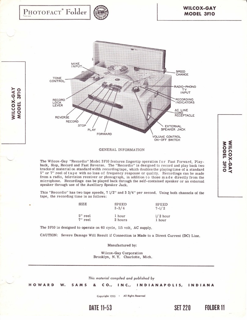
The Wilcox-Gay "Recordio" 5U Series "Imperial" Model features fingertip operation for
Fast Forward, Playback, Stop, Record, and Fast Reverse. A I'Tape Timert' enables you to lo-
cate,immediatelyandexactlyany selection on a recorded tape. This recorder is designed to re-
cord and playback two tracks of material on standard width recording tape. Any reei size up to
?" can be use.{. Two neon recording indicators simplify the recording level setting. New re-
cordings can be made on previously recorded tape lini:e the erase head is automatically po-
sitioned when the "Record, button is pressed, or the same recording may be played back in-
definitely. Recordings canbemadefromaradio, television receiver, or phonograptr, in addition
to those made directly from the microphone.
The Model 5U has two large high-quality speakers and full frequency response is assured
by the addition of two high frequency electrostatic I'tweeter' spealcers. Three jacks are pro-
vided for the use of external speakers when greater volume and better coverage are needed.
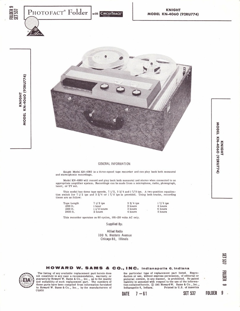
The Model 5U has two tape speeds, 3 3/4" and 7 l/2* per second, Using both tracks of
the tape the recording time is as follows:
3
9=
EIF
rfl
E*
(ao
o
=.<
o
ln
Thisunitisdesignedto operate on 60 cycle, 115 volts, AC supply only. Before connecting
to your line supply, be absolutely certain that it agrees with the above specifications.
Manufactured by:
Wilcox - Gay Corporation
Charlotte, Mich.
TAPE
TIMER
PLAY FORWARD KNOB
Ihis moferiol compiled. ond published by
& co., lNc., INDIANAPOLIS,
Copyright 1956 All Righrs Reserved
DATI 5- 5$
INDIANA
sET 310 FOTDER IO
HOWARD lf. 5Ail5

BIAS
ADJUSTMENT OVHRTSAD
fNDICATOR
ADJ USTMENT
hd$RMAL
l$',l0lCATOR
ADJUSTMENT
Figure 2
OPERATING INSTRUCTIONS
Preparation For Operation-
1. Remove the AC power cord, ?" reel of tape,
empty reel and the microphone from the rear storage
compartment.
2. Depress the "Stop" button.
3. PIug the AC cord into a convenient wall re-
ceptacle of the proper rating.
4. Setspeed change knob to ?.50 or 3. ?b as de-
sired.
5. Place Remote- Normal switch in *Normal'
position.
CAUTION: Do not turn speed change knob unless "Stop"
button is depressed.
When the Forward or Reverse buttons are de-
pressed, the Record and Play buttons are loeked so that
they cannot be pressed down, with the possibility of
spilling tape. The buttons should always be pressed
down firmly untit they latch and the Stop button must
be depressed before changingfunctions or speeds of the
recorder.
IMPORTANT: Always depress the Stop button when
the machine is not in use.
Page 2
Speed Change Knob-
Thearrowonthe speed change knob should point
at 7.50 or 3. ?5 according to the speed desired. This
recorder hastwo speeds, 7 L/Z"and 3 3/4"persecond .
Thearrowpointingat ?.50 means the unit will operate
at the fast speed or 7 L/2', per second.
CAUTION: Turning the speed change knob while the unit
is operating will not change the speed.The
Stop button must be depressed before thd
speed can be changed"
Threading The Tape-
1. Place a full reel of tape on the left (supply)
spindle, making certain one of the reel slots catch the
protrusionsof the pan. Unwind about 14" of tape from
the supply reel.
2. Insert free section of tape into the tape slot.
3. Insert free end of tape into one of the three
slots in the hub of the right (take-up) reel and white
holdingthe tape in place give the reeltwo or three turns
until the tape is secured.
4. The dull side of the tape should always face
away from the operator (rear of unit).
To Record From Microphone-
1. Turn the On-Off Volume control to the right
until a click is heard and allow about 30 seconds for

**
Figure 3
=
gs
lrt F
r6
EP
oGt
o
=.<
o
tn
the unit to warm up. The pilot tight located above the
Stop button will glow when the unit is turned on.
2. Insert the microphone plug into the IMicro-
phone" input.
3. Move the record lock button (21) downward
with the left hand. This releases the safety lock which
prevents accidental erasure.
4. Depress the ilRecordrt button with t}re right
hand (while holding record lock button (21) with the
left hand) until it latches.
5. Adjust the'Volume" control until the'Normaf'
indicator just flashes, while speaking into the micro-
phone. Whenthe "Volume" control is advanced too far
the "Overloadil indicator witl flash and the recording
will be distorted. T o prevent overload, lower the
"Volume" control to a point where the il Overload rt
indicator will not flash.
6. The t'Tonet' control does not operate during
recording. When recording from radio, setthe radio
"Tonet' control for maximum treble.
To Record From External Radio, TV. Or phonograph-
1. Insert the phonograph pickup plug into the
"Radio-P. A. -Phono" jack.
2" For radio or TV recording, connect patch
cord, part No. C20. 233 to the voice coil of the iadio
or TV receiver speaker by means of the alligator clips.
Plug into t'Radio-P. A. -Phonoil jack.
3. Proceedasdescribedunder "ToRecord From
Microphone".
NOTE: Remove patch cord after recording is com-
pleted.
To Use Second Track-
1. Depress th6 "Stop"button whenall the tape has
wound onto the take-up reelo
2. Remove reel containing tape and place on left_
hand supply pan"
3o Place empty reel on right-hand take-up pan.
4, Thread tape as previously described.
To Play Recordings-
1. Turn on unit with ilVolume" control knobo
2. Thread tape as described under "Threading
The Tapeo t'
3" Set the speed change knob (1) to the speed at
which the recording was made.
4. Depress "Play" button until it latches,
Page 3

5. Adjust "Volumett and "Tonet' controls to de-
sired listening levelo
High-Speed Forward Or Reverse-
When it is desirable to play a certain portion of
the tape over again it is not necessary to rewind the
entire tape" By depressing the'Forward'or'Reversd'
button the tape will advance (or reverse) at a rapid
speed.Several minutes of normal recording can be skip-
pedin a few seconds by the ,'Reversel and "Forward"
buttons.
Tape Timer-
If, when making reeordings or playinga recorded
tape, you wish to play back a certain recordi.ng, note
t}te readingon the timer scale when the particular re-
cording is being made or heard. Rewind the tape until
thenumberyouhave noted appears on t}re scale, press
"Stop"button, thenpress "Play"buttonand you are now
listening to the recording you wanted.
Whenstartinganew reel of tape or re-recording
a reel, reset the indicator pointer to "O" by rotating
tfie reset knob. By starting at "O" on all tapes, the
number location can be cataloged for each selection
on any reel"
To Edit And Splice Tape-
NOTE: Since it is impossible to edit and splice one
track without affecting the other, recordings
which are to be edited should be limited to one
track only.
1. Thetapemaybeeditedby cutting out unwanted
portions, or by j oining sele cti ons into another sequen ce.
Announcements may be inserted between selections,
etc. Unused sections oftape can be spliced together for
re-use.
2. Forbestresults, eut tape at a slightdiagonal
join ends together with splicing tape on the glossy side
and trim off any excessive width.
Erasing Recorded Material-
Whenthe record button is depressed, the erase
head is automatically positioned, erasing any previors
recording before a new one is made. you may erase
materialno longer needed, without reeording, by de-
pressing the "Re cordn button and turning the,T'olume.'
control knob to the minimum volume position or ex-
treme counter-clockwise position just before the re-
corder shuts off. One track is erased at a time. To
erase the second track, reverse the reels and repeat
the above operation.
To Use Recorder As A Public Address System-
The Model 5U, with its own speakers, can be
used as a public address system by depressing the
"Stop"buttonand pressing the Microphone switch. Set
ToneandVolumetothe desired level. A recording can
bemade at the same time by depressing the "Recordil
button.
CAUTION: Whenusingthepublic address feature, see
that the microphone is as far away from the
speakers as possible, to prevent 'Teed-
back" squeal.
Page 4
Remote Control Operation-
The "Instant Stop Start" remote control unit sup -
plied with your rrRecordio" plugs into a five pin socket
locatedonthelefthandsideof the "Recordio" (Fig. 1) .
Itenablesthetape to be stopped or started at any time
duringRecord or Play from a distance of up to fifteen
feet. Pressingtheremote contlolswitch once will stop
the tape instantly; presqing the switch again will re-
startthetapeatthe identical spot at which you stopped
it. ADJUSTMENTS
Dis?ssembly Instruction-
1. Remove push-on type "Volume" and "Tonet'
control knobs.
2. Remove two Phillips head screws located under
knobs.
3. Remove seven Phillips head wood screws from
around front panel.
4. Rernove two hex. head screws located under
front escutcheon (22).
5. Openbackpaneland remove leads from b x ?"
oval speaker,
6" Remove electrostatic speaker plug"
?. Remove complete unit by pulling out front of
casel the remaining leads are long enough to permit
complete removal of unit from case"
NOTE: The tubes may be serviced without re-
moving unit from case by removing grille
at rear of case.
Record-Play Head Adjustment-
WTo adjust the record-play head (64) for max-
imumfrequency response, make the following adjust-
ment:
1. Remove the rear escutcheon (16) and rear
escutcheon plate (20).
2. Properly thread an alignment tape or a good
recorded tape on the machine.
3. Setthe controls as described under 'tlo Play
Recordings".
4.With the unit playing turn head adjustment
screw (644') right or left untii maximum high fre-
quencies are obtained.
Pressure Pad Adjustment-
@front escutcheon (22).
2. Depress the "Play" button. Do not turn the
recorder on.
3. Use a pencil type postal scale and check the
amountofpressurenecessaryto just pult the pad avsay
from the tape. The test should be made on the end of
the pressure pad for I 3/4o2.+l/4o2. pressure.
(a)The record head pressure pad is adjusted by
the locked adjustment screw (61).
(b)The guide post pressure pad (56) is adjusted
by bending the pressure pad spring. It must be ad-
1. Remove the

ffi
,B 1
ig , i
iiffi','' . r'= :"'.' i#
3
g=
trt F
r6
E*
oO
o
=.<
o
u
Figure
justed for minimum pressure against the tape.
4. After the adjustments are made depress the
"Stop" button and replace the front escutcheon.
Erase Head Adjustment-
1. With the escutcheons removed check the erase
head (59) to see if it is parallel with tape.
2. Check to see if the top edge of the tape coincides
with the top end of the diagonal slot in the erase head
(junction of long diagonal slot and short vertical slot) .
Toadjustlevelof tape, loosen set screw (50), see ex-
ploded view, and rotate tape guide post (b1) to move
tape up or down. Tighten set screw (b0).
3. Afterthisadjustmenthas been made, check to
see if the tape moves forward approximately 1,/64"when
the "Record" button is depressed. If not, loosen the
forward adjustment screw (59A), see Figure 2, and turn
the screw in or out as required to obtain this l/64rt
movement. Tighten the lock nut"
Br?ke Shoe Adjustment-
1.In order to adjust the brake shoes, the com-
plete mechanism must be removed from the carrying
case and the speakers disconnected.
2. With all push buttons in the up position the brake
shoesonthebrakespring (131) should clear the drums
by approximately L/8".
3. Depress the "Stop" button while observing the
brake shoes. Both brake shoes must contact the drums
at the same time and with equal pressure.
4
4" The adjustment is accomplished by bending
the spring arm (131).
Hum Control Adjustments -
The dual hum control is preset at the factory.
However, if anyof the tubes are replaced these controls
should be reset for minimum hum. If the 58?9 only is
changed, set the Recordio to "Play", turn the "Volume"
control to maximum (clockwise) and adjust the outer
shaft of hum control for minimum audible hum. If other
tubes are changed, set recorder to "Record", plug a
speakerintothe 600 ohm jack and turn "Volume" con-
troltomaximum, adjust inner shaft of hum control with
a small screw driver for minimum hum, then set re-
corder to "Play" and repeatfor outer shaft adjustment.
Adjustment For Slow Take-Up Reel-
There are some instances where the spring drive
belt (8), see Figure 2 and exploded view, stretches
after a period of time. When this happens, the takeup
torque will be insufficient to wind tape properly into
the takeup reel. In this case, the belt should be re-
placed as follows:
t. Remove rear escutcheon (16) and rear es -
cutcheon plate (20).
2. Remove unit from cabinet"
3" Loosen brake drum set screw (94).
4. Lift up reel pan and shaft and remove spring
drive belt.
S.Install new belt.
Page 5

A PHOTOFACT "EXPLODED" VIE\T
@ Howard \(- Samr & Co., lnc. '1956
ffi*
ffi
$€
B*
iii
ril
A/'ffi-
Y
A
A,..Y
Y
Figure 5A. Exploded View Of Parts Above Baseplate.
Page 6

=
g=
tilF
Ffl
E*
l,lG)
o
=.<
o
UI
@-__-_---*" "-*-------@)
H@
VAA A4
\:1/--* e
A PHOTOFACT "EXPLODED" VIEW
o How*d w. sim, a co., lnc. 1956
Figure 58. Exploded View Of Parts Below Baseplate
Page ?

6CG7
POWER
SOCKE
t2AX7
ry
\
@
6AQ5
6AQ5
5Y3
Top View Of Amp. Chassis
Bottom View Of Amp. Chassis
Page 8


=
9=
tnF
FN
E8
laG)
o>
=.<
o
la
c31
c32
c33
c34
c35
R1
R2
R3
R4
R5
R6
R?
R8
R9
Rl0
R11
R12
R13
Rl4
R15
R16
R1?
R18
R19
R20
R21
P'22
R23
P.24
R25
R26
R2?
R28
R29
c-4. 109-13
B-4. 129-?
c-4.115-1
c-4. 109-33
c-4.109-2
c-8.227 -5
c-8.23r-2
D-?.101-1
D-?.101-23
D-7. 101-12
D-?. 102-94
D-7.101-12
D-?. 101-93
D-?. 101-86
D-?. 101-1?
D-?.101-1
D-?.101-1
D-7. 103-1
D-?.101-?9
D-?" 101-1
D-?.101-1
D-?.101-44
D-7.102-11
D-?.102-11
D-7.102-72
D-?.101-86
D-7.101-11
D-7. 101-114
D-?.103-62
D-?.101-121
D-?.101-121
D-?. 101-1
D-7.102-72
D-?.101-1 Resistor, 100K. 1/2 W. 1
Cap. Ceramic, 1500MMF
Cap. Disc, 1500MMF@) 1500V.
Cap. Disc, 5000MMF.
Cap. Ceramic, 10000MMF
Cap. Ceramic,4TOMMF
Volume Cont. & Switch, lMeg
Tone Cont. ,250K
Resistor, 47 OI(, I / 2 W, tW
Resistor, l.5K',l/2 W. 1ffi (Some
Models Use A 1.8K Resistor: In
This Application)
Resistor, 41OK,l/2 W, 10%
Resistor,4?K, 1W. 10%
Resistor, 410K, t/2 W, LW
Resistor, 68K,L/2 W,lffi
Resistor, 47K, L/2 W, Lqo
Resistor, 4. ?Meg, t/2 W,lqa
Resistor, 100K, t/2 W, L%
Resistor, 410K, l/2 W, LW
Resistor, 39K,2W, 10%
Resistor, SSK,L/2 W,LW
Resistor, 1OMeg, l/2 W,lVh
Resistor, 2. 2Meg, l/2 W, LNlo
Resistor, 4. 7K, L/2 W, lq%
Resistor, 120K, 1W, 1(%
Resistor, 120K, 1W, 10%
Resistor, 15K, 1W, lqb
Resistor, 47K,L/2 W,lq%
Resistor, 22OK,l/2 W, 1qb
Resistor, 220K,L/2 W, 10b
Resistor, z?OKf,l, 2W, lm
Resistor, 330K,t/2 W, 10%
Resistor, 330K, I/2 W, 10%
Resistor, 470K,I/2 W, 1qb
Resistor, llK,l/2 W, 1d%
R38
R39
T1
T2
sP1
sP2
sP3
sP4
L1
L2
M1
M2
M3
M8A
MBB
M8C
M9
M10
M4
M5
M6
M7
D-?.101-44
D-7.101-1
c-6.215-10
D-?. 101-
D-?.102-23
D-7.103-58
?. 103-23
7. LO2-217
B-8. 234
B-8.234
D-7.101-11
D-9.2?g-0
c-9.277A
30.341-2
30.341-2
30. 347
30. 347
B-1. 55?
B-1.556
45-2003
45-2036-0
45 -2036-0
c-4.142
c-4-. t42
B-4. 145
B-4. 145
1 1. 239
33.461
tL-2233
Resistor, 4. 1I(, t/2 W, tW
Resistor, t00K, L/2 W, tW
Resistor, 3. 3q ?W, 10%
Resistor, 100K,l/2 W, 10%
Resistor, 1K, 1W, 10%
Resistor,220A,2W,lqo
Resistor, 33C4 2W, 1m
Resistor, t}g2W,2W
Recording Hum Control 500QFot.
Play Hum Control 500OPot.
Resistor, t80K,l/2 W, 10%
Power Trans.
Push-pull Output Trans"
5 x ? P. M. Speaker
5 x ? P. M. Speaker
Electrostatic Speaker
Electrostatic Speaker
Osc. Coil R. F. (Tapped)
Bias Freq. Load Coil
Pilot Lamp #44
Neon Lamp NESlNormal Indicator
Neon LampNESl Overtoad
Indicator
Trimmer Bias Adj. (3-35MMF)
Trimmer, Bias Osc. Freq.Adj.
(850-1150MMF)
Trimmer Normal Ind. (5-?0
MMF)
Trimmer Overload Ind. (5-?0
MMF)
Play Record Sw. (Bear View)
Play Record Sw. (Rear View)
Play Record Sw. (Front View)
Selenium Rectifier (250MA)
Remote-Normal Switch
MECHANICAL PARTS LIST
Ref.
No. Part
No. Description Ref
No. Part
No. Description
10
11
t2
13
1
2
3
4
5
6
I
I
I
14
15
16
t7
18
19
20
2l
22
23
24
25
c-13.253-?
73-2254-3
57-6C-620-1
5? -4C-405-?
B-32.302-2
73-223t-3
35.887
B-31.351
5?-3589-1
c-13.312
33. 458
B-31.359
B-32. 315
5? -46C -806 -1
13-2254-3
D-t3.292-4
35.851
57-1C -618-1
?3 -2334-1
B-19.9?5-2
B-32.308-4
E-13.293-4
33. 415
28. 163
D-31.363
Speed Shift Knob (Black)
Felt Washer
#6-32 x L L/ "R.II. M. S. Phillips
#4-40 x 5/16"0.II. M. S. Phillips
Timer Knob (Crome plated)
#4 Internal Lockwasher Stl.C. P.
Reel Pan Assy-Includes Items
9-11-12-13
Reel Drive Spring (Belt)
6-32 x 3,/18'Bristol Hd. Set
Screw
Control Knob(Black & Chrome)
3/16 Dia. Stl. Ball
Compression Spring
Brake Drum Shaft (Take-up
Reel)
#8-32 x 3/8R. H. M. S.Phillips
Felt Washer
Rear Escutcheon (Black)
Timer Shaft & Pointer Assy.
#6-32 x 1 l/SPhillips R. H. M. S.
#6 Cantlink Washer
Rear Escutcheon Plate (Black)
Record Lock Button
Front Escutcheon (Black)
t'E" Ring Retainer
Linen Washer
Baseplate Overlay
26
21
28
29
30
31
32
33
34
35
36
37
38
39
40
4L
42
43
44
45
46
47
48-2213 -1
B-19. 985-1
B-33.8?8
54 -2030-35
73-223L-5
48-2219-l
5? - 1C -603 -2
?3-2334 -1
B-19. 858
54 -2030-35
D-35.861-4
B-33.459
B-33.446
B-32. 259-1
B-32. 285-1
13-2231-4
5?-lC -608-1
B-19. 876
35. 869-1
B-31. 337
B-19.859-1
13-2241-154
5?-46C -806-1
Hex. Nut, 3/8-32 x L/2
Bracket for Input Jack
Midget Jack
Drilled Pctuet L/4 x .122 x 7 /32
#8lnt. Lockwasher
Keps 6-32 x5/L6 Hex. Nut & Ext
Lockwasher
#6-32 x 3/t68. H. M. S. Brz.
Phillips
#6 Cantlink Washer
Push Button Retainer Bracket
Drilled Rivet 1/4 x .122 x 7 /32
Base Plate Assy. (Dull Elk. )
Phono Jack
Spacer
Capstan Shaft (To be used on
60 cy. units)
Capstan Shaft (To be used on
50 cy. units)
#Olnternal Lockwasher
#6*32 x 1/2Phillips B. tI. M. S.
Push Button Lever
Push Button Assy.
Push Button Return Spring
Hinge Bracket for Push Button
Flat Washer 5/l6O,D. X. x . 144
x .025
#8-32 x 3/8 R. H. M. S.
Page 13

Ref.
No.
51
52
53
54
55
56
5?
58
59
60
61
62
63
64
65
66
6?
68
69
?0
1L
72
73
74
?5
?6
77
78
?9
80
81
82
83
84
85
86
87
88
89
90
91
92
93
95
96
9?
98
99
100
101
L02
103
104
105
106
107
108
109
110
111
tt2
113
tt4
B-31. 343
B-19. 8?0A
5?-3439-0
B-32. 300
48-410-1
B-32.260
B-35.794
B-31. 361
B-35.764
73-2233-l
48-22L6-l
c35. ?56.A
B-35. 882
5?-16C-606-1
57-3439-0
B-32. 309
c-36.156-1
13-224t-148
B-19. 881
B-31.360
c-35.758
B-35. ?64
B-33.412
B-19.868A
B-33.409
73-2340
B-33.404
B-31.351
73-2340
B-35. 8?1
B-35.774
B-31. 333
1 10-488
B-31.338
c-35.835
B-31.339
B-33.412
B-33. ?59
54-2030-35
73-224L-18
B-19.863
B-28. 163
13-223L-5
5?-1 1C -804-1
c-35-823-B
5?-3589-1
B-32. 316
B-28. 175
D-35. 753-3
73-223t-5
57-2t02-3
B-31. 362
B-35. 75?
B-32.275-1
13-2340
B-33.405
13-2254-6
13-2241-150
B-33.409
B-33. 118
B-33.445
73-223t-4
5?-1C -603-2
73-2231-4
Locking Plate-for Push Buttons
#6-32 x 3/l6Bristol llead Set
Screw
Tape Guide Post (Left)
#6-32 Nut Steel
Tape Guide Post Spacer
Erase Head Plate rneludesltem 59
Erase llead Tension Spring
Pressure Pad (Felt)2 used
Int. Lockwasher
#2-56 x 31116 Hex.Nut
Erase Head
Record Actuating Lever Assy.
#6-32 x 3/8R.II. M. S.
#6-32 x 3rll6Bristol Head Set
Screw
Tape Guide Post (Right)
Tape Recording llead (Shure
TBl6H)
Flat Washer
Playbaek Actuating Lever
Pinch Roller Tension Spring
Playback Slide Plate Assy.
Pressure Pad Spring Assy.
Push-On-Stud Nut, 3/16"Stud
Record Slide Plate
Hairpin Clip
Linen Washer
Pinch Roller
Reel Drive Spring (Belt)
Linen Washer
Pinch Roller Plate Assy.
Record Interlock Assembly
Switch Arm Link
Switch Lever Assy.
Brake Return Spring
Brake Slide Plate Assy.
Idler Lever Tension Slring
Push-On-Stud Nut, 3/16 Stud
Shift Plate Assembly
Drilled Rivet 1,/4 x .122 x7/32
Flat Washer
(Bottom View of Item 36)
Drive Mounting Plate Bracket
Linen Washer
#8 Int. Lockwasher
#8-32 x 1/4 R. H. M. S.'
Brake Drum & Bushing Assy.
#8-32 x 1/4Bristol Hd. Set Screw
Brake Drum Shaft (Grooved)
Counter Belt (Rubber)
Drive Mounting Plate Assy.
Internal Lockwasher
#8-32 x 1/4 R.II. M. S.
Screw
Washer
Sub-Idler Tension Spring
Sub-Idler Plate Assy.
#8-32 ItE Shoulder Screw
Linen Washer
Sub Idler Wheel
Felt Washer
Flat Washer
Hairpin Clip
Spacer
Gear Train for Tape Index
#6lnt. Lockwasher
6-32 x 3/168. H. M. S. Brz.
#6lnt. Lockwasher
116
LL7
118
119
t20
L2L
t22
123
L24
125
126
L27
128
t29
130
131
132
133
134
135
136
13?
138
139
140
141
t42
143
t44
145
146
t47
148
149
150
151
t52
153
154
155
156
15?
158
159
160
161
L62
163
164
165
166
16?
168
169
5?-1C-614-1
B-19.995
48-2221
B-28,159
B-33. 411
28.181
35-2018
33.418
73-2241-L43
13-2254-3
c-19.88?-1
73-2254-3
73-224L-t43
33.415
35. 834-2
B-32.2?5-18
B-35. 8?2
8.32.275-t
B-23. 163
28.181
B-33.406
73-2254-6
13-224L-150
B-33. 418
B-13.25?-1
57 -3589-1
B-28. 163
B-28. 163
c -35,823 -B
B-19.862
77-2231-5
67-2102-3
B-32. 3?1-1
33. 45?
35.8?3
48-22t9-l
B-33.411
73-224t-r34
36.153
B-19.961
B-33.40?-1
51 -3182
57-2t09-2
B-31. 324
B-32.264
B-35. ?68
5?-3589-1
B-33.409
B-28. 163
B-33.408
B-28. 163
B-31.32?
B-32.288
57 -2L02-3
73-223t-5
73-224t-t43
1 10-4?
B-32.291-1
5? - 1C -603 -2
B-31. 3354
c-35.816-1
#6-32 x ?/SPhiliips B.II. M. S.
Aux. Motor Bracket
#10-32 Hex. Nut (Elastic Stop
Shock Mount
Flat Washer 3/4O.D. x3/L6
ldler Drive Belt
Rubber Grommet
Truearc Retaining "E" ring
Flat Washer
Felt Washer
Fan Blade
Felt Washer
Flat Washer
Push-On- Fastener
Idler Lever Assy"
#8-32 HH Shoulder Screw
Brake Spring(part of Item 82)
Lever Assembly
8-32 HII Shoulder Screw
Linen lVasher
Idler Drive Belt (Part of 120)
Idler Drive Sheave
Felt Washer
Flat Washer, Blued Steel
Truarc Retaining 'rE" ring
Flywheel
#8-32 x l/4Bristol Head Set
Screw
Linen Washer
Linen Washer
Brake Drum & Bushing Assy.
Angle Bracket for Mounting
Drive Assy.
Internal Lockwasher
8-32 x 1/4R. H. M. s.
Spacer
Solenoid
Solenoid Plate (Includesltem 149)
Keps 6-32 x 3/8Hex. Nut & Ext.
Lockwasher
Flatwasher 3/4O.D. x 3/L6
I. D. X.
Screw
Flatwasher 5/16 O.D. X. 130 x
.031
Motor, Round Type (Fasco)
Speed Control Shaft Detent
Spring
ttCttWasher
Shift Plate for High Speed
6-32 x 3/l6Phillips B. H. M. S.
Idler Spring (Tension)
Idler Slide Bushing
Idler Slide Plate(Incl. Item 161)
8-32 x 1/4Bristol Hd. set screw
Hairpin Clip
Linen Washer
Rubber Bonded Idler Wheel,
Linen Washer
Idler Lift Compression Spring
Motor Pulley
8-32 x L/4 R. H. M. S.
#8 Internal Lockwasher
Flat Washer
Idler Throw-Out Lever
Shoulder Washer
#6-32 x 3/16Phi11ips B. H. M. S.
Brake Pad, Felt
Speed Control Shaft Assy.
Page 14
Table of contents
Other Wilcox-Gay Voice Recorder manuals
