SST Automation GT100-EI-RS User manual

Modbus / EtherNet/IP Adapter
GT100-EI-RS
User Manual
V 1.4
Rev D
SST Automation
Email: [email protected]
www.sstautomation.com

User Manual
Modbus/EtherNet/IP Adapter
GT100-EI-RS
WWW.SSTAUTOMATION.COM
Important Information
Warning
The data and examples in this manual cannot be copied without authorization. SST Automation reserves the right
to upgrade the product without notifying users.
The product has many applications. The users must make sure that all operations and results are in accordance
with the safety of relevant fields, and the safety includes laws, rules, codes and standards.
Copyright
Copyright © 2022 by SST Automation. All rights reserved.
Trademark
is the registered trade mark of SST Automation.
Technical Support Contact Information
www.sstautomation.com
E-mail: support@sstautomation.com

User Manual
Modbus/EtherNet/IP Adapter
GT100-EI-RS
WWW.SSTAUTOMATION.COM
1
Catalog
1 Product Overview ......................................................................................................................................................1
1.1 Product Function ............................................................................................................................................ 1
1.2 Product Features .............................................................................................................................................1
1.3 Technical Specifications .................................................................................................................................1
1.4 Revision History .............................................................................................................................................2
2 Hardware Description ................................................................................................................................................3
2.1 Product Appearance ........................................................................................................................................3
2.2 Indicators ........................................................................................................................................................ 4
2.3 Button ............................................................................................................................................................. 4
2.4 Interface ..........................................................................................................................................................4
2.4.1 Power Interface ................................................................................................................................... 4
2.4.2 Ethernet Interface ................................................................................................................................ 5
2.4.3 RS485/RS422 Interface .......................................................................................................................5
2.4.4 RS232 Interface ...................................................................................................................................6
3 Installation ................................................................................................................................................................. 7
3.1 Machine Dimension ....................................................................................................................................... 7
3.2 Installation Method ........................................................................................................................................ 7
4 Quick Start Guide ......................................................................................................................................................8
5 Software Instructions .................................................................................................................................................9
5.1 Software Interface Description ...................................................................................................................... 9
5.2 Device View ................................................................................................................................................. 10
5.2.1 Ethernet Configuration View ............................................................................................................ 10
5.2.2 Subnet Configuration View-Modbus Master ....................................................................................12
5.2.3 Subnet Configuration View-User Config ..........................................................................................16
5.3 Tools ............................................................................................................................................................. 17
5.3.1 Ethernet Configuration ......................................................................................................................17
5.3.2 Upload ............................................................................................................................................... 18
5.3.3 Download .......................................................................................................................................... 20
5.3.4 Calculate Auto Mapping ................................................................................................................... 22
5.3.5 Mapping Address Conflict Detection ................................................................................................22
5.3.6 Export Excel ......................................................................................................................................24
6 Working Principle ....................................................................................................................................................25
6.1 Modbus Master .............................................................................................................................................25
6.2 User Config .................................................................................................................................................. 26
6.3 EtherNet/IP Connection Parameters ............................................................................................................ 27
6.4 How to Read/Write I/O Data ........................................................................................................................28
6.4.1 Read and Write Data using I/O mode(Recommended) .................................................................... 28
6.4.2 Read and Write Data using MSG ......................................................................................................33

User Manual
Modbus/EtherNet/IP Adapter
GT100-EI-RS
WWW.SSTAUTOMATION.COM
1
1 Product Overview
1.1 Product Function
GT100-EI-RS is an adapter which can realize the mutual conversion between Modbus protocol and EtherNet/IP
protocol. It can connect Modbus (other serial protocol) devices to EtherNet/IP network. Modbus side supports
RS485/RS422, and also supports RS232, it only uses one interface during data communication.
1.2 Product Features
One RS485/RS422 or RS232 interface with independent 1KV photo electric isolation.
Ethernet 10/100M self-adaptive.
IP address conflict detection.
Modbus network communication debug function.
Provide easy-to-use configuration software SST-MI-CFG.
1.3 Technical Specifications
[1] EtherNet/IP network is independent with Modbus network.
[2] Ethernet 10/100M self-adaptive.
[3] IP address conflict detection.
[4] Support ODVA standard EtherNet/IP communication protocol.
[5] Serial port parameters:
RS485/RS422 or RS232 interface, half-duplex.
Baud rate: 1200, 2400, 4800, 9600, 19200 , 38400, 57600 and 115200 bps can be selected.
Parity check mode: None, Odd and Even can be selected.
Stop bits: 1,2 optional.
[6] Modbus master:
Function code: 01H, 02H, 03H, 04H, 05H, 06H, 0FH and 10H.
Each master can configure up to 48 Modbus commands.

User Manual
Modbus/EtherNet/IP Adapter
GT100-EI-RS
WWW.SSTAUTOMATION.COM
2
03H and 04H support "Word / Byte mapping" and it is easy to solve the format conversion problem of
big endian and little endian between two network data. The gateway can connect 8 Modbus slave
devices for RS485 connection.
[7] User Config: supports character timeout, character number and delimiter control mode, and has auto sending
function.
[8] Serial port has independent 1KV photoelectric isolation.
[9] Max input and output bytes of EtherNet/IP:
Max input bytes: 492 bytes (256 bytes under universal mode).
Max output bytes: 492 bytes (256 bytes under universal mode).
[10] Power supply: 24VDC (11~30VDC), 70mA (24VDC).
[11] Working temperature: -40℉~140℉(-40℃~60℃), Humidity: 5% ~ 95% (non-condensing).
[12] Dimensions (W*H*D): 1.0 in*4.0 in *3.6 in (25mm*100mm*90mm).
[13] Installation: 1.4 in (35mm) RAIL.
[14] Protection level: IP20.
1.4 Revision History
Revision
Date
Chapter
Description
V1.2
7/14/2015
ALL
New release
V1.4
12/26/2016
ALL
Revision for GT100-EI-RS V1.4
V1.4, Rev A
1/17/2017
ALL
Change the default Assign IP Mode to DHCP
V1.4, Rev B
3/18/2018
ALL
Change the default IP address to 192.168.1.XXX
V1.4, Rev C
6/17/2021
Chapter 2.3, 3.1
Revision and picture updated. Change the default IP
address to 192.168.0.XXX
V1.4, Rev D
1/12/2022
ALL
Update the format.

User Manual
Modbus/EtherNet/IP Adapter
GT100-EI-RS
WWW.SSTAUTOMATION.COM
3
2 Hardware Description
2.1 Product Appearance
Note: This picture is for reference only. The product appearance is subject to the actual product.
Ethernet Indicators
Power Interface
Ethernet RJ45 Interface
RS232 Interface
Button
Serial Indicators
RS485/RS422 Interface

User Manual
Modbus/EtherNet/IP Adapter
GT100-EI-RS
WWW.SSTAUTOMATION.COM
4
2.2 Indicators
Indicators
Status
Descriptions
ENS
(IP indicators)
Red off
IP address launch is normal
Red blinking
DHCP
SNS
(EtherNet/IP network status
indicators)
Green on
Ethernet/IP connection is established, communication
is normal
Green blinking
EtherNet/IP connection is not established
TX, RX
(Serial data indicators)
TX, red blinking
Serial port is sending data
RX, green blinking
Serial port is receiving data
2.3 Button
The button is located at the top of the adapter.
Action
Descriptions
Press button down for at least 3 seconds, and
release the button after all indicators are off.
Reset to default settings - 192.168.0.11
Note: The reset action will clear the configuration, please download the configuration firstly before using.
2.4 Interface
2.4.1 Power Interface
GT100-EI-RS has one power interface. It is recommended to use 24VDC power.
Pin
Function
1
Power GND
2
NC, not connected
3
24V+, DC Positive 24V

User Manual
Modbus/EtherNet/IP Adapter
GT100-EI-RS
WWW.SSTAUTOMATION.COM
5
2.4.2 Ethernet Interface
Ethernet interface uses RJ-45 connector. its pin (standard Ethernet signal) is defined as below:
Pin
Signal Descriptions
S1
TXD+, Transmit Data+
S2
TXD-, Transmit Data-
S3
RXD+, Receive Data+
S4
Bi-directional Data+
S5
Bi-directional Data-
S6
RXD-, Receive Data-
S7
Bi-directional Data+
S8
Bi-directional Data-
2.4.3 RS485/RS422 Interface
Serial interface uses 5-pin terminal and users can wire it according to the wiring instructions on the panel.
When RS485 is in the communication of point to multi-point, to prevent the reflection and obstruction of signal,
users need to use two terminal resistances in furthest ports of line, and the parameters are 120Ω 1/2W.
Note: There is no terminal resistor inside RS485/RS422 interface of GT100-EI-RS.
Pin
Function
1
R-, RS422 Receive Negative
2
R+, RS422 Receive Positive
3
GND
4
D-, RS485/RS422 Transmit Negative
5
D+, RS485/RS422Transmit Positive

User Manual
Modbus/EtherNet/IP Adapter
GT100-EI-RS
WWW.SSTAUTOMATION.COM
6
2.4.4 RS232 Interface
RS232 interface pin description is shown as follows:
Pin
Function
1
TX, Connect user device RS232's RX
2
RX, Connect user device RS232's TX
3
GND, Connect user device RS232's
GND
User Manual
Modbus/EtherNet/IP Adapter
GT100-EI-RS
WWW.SSTAUTOMATION.COM
7
3 Installation
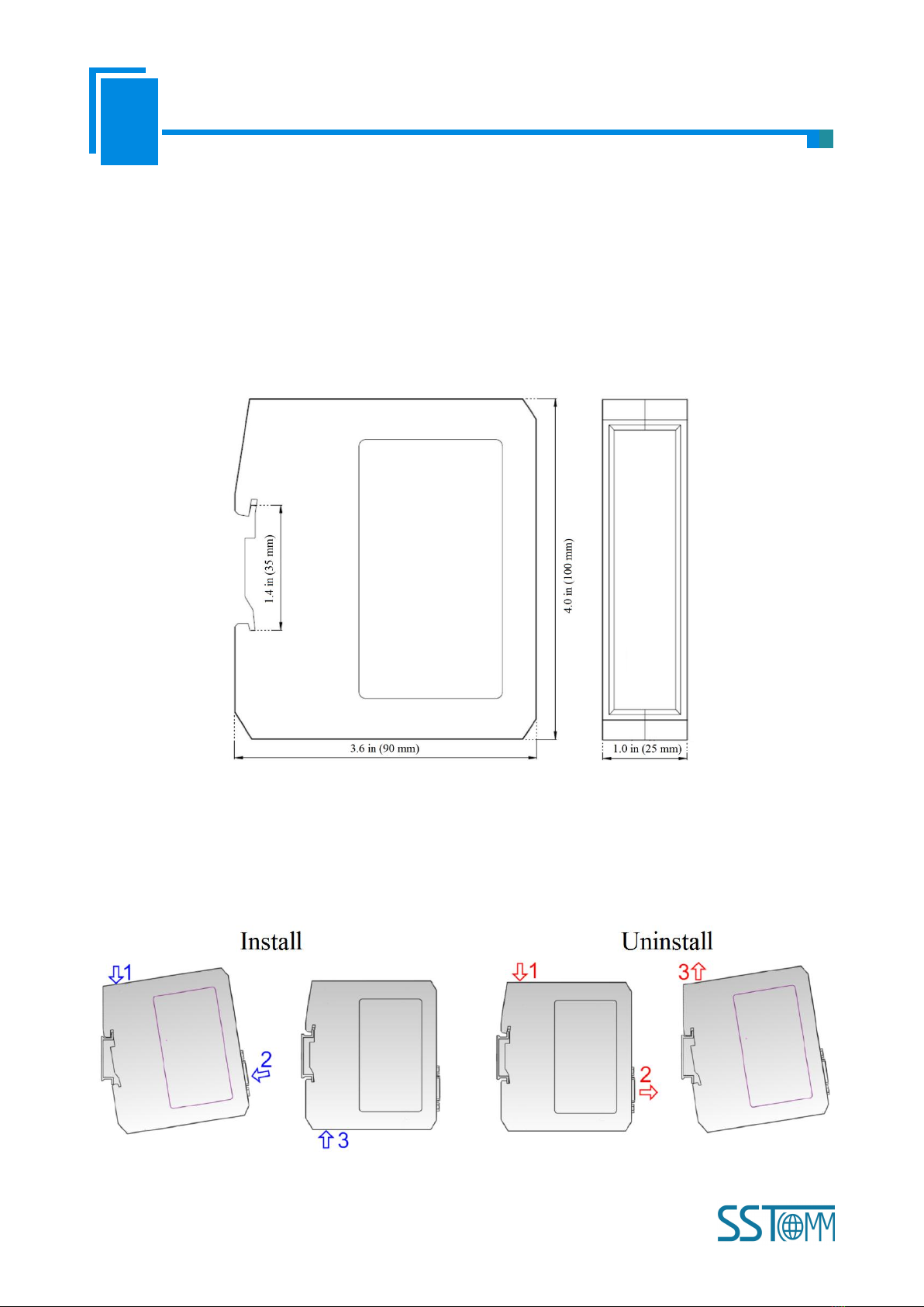
3.1 Machine Dimension
Size (width * height * depth):
1.0 in * 4.0 in * 3.6 in (25 mm * 100 mm * 90 mm)
3.2 Installation Method
Using 1.4 in (35mm) DIN RAIL

User Manual
Modbus/EtherNet/IP Adapter
GT100-EI-RS
WWW.SSTAUTOMATION.COM
8
4 Quick Start Guide
Basic steps when configuring G100-EI-RS :
1. Wiring:See also Chaper 2.4 Interface.
(1)Connect the network port of the gateway to the PC with a network cable for downloading the
configuration.
(2)Connect the serial port of the gateway to the serial device for communication.
(3)Connect the gateway power supply and power on.
2. Download SST-MI-CFG software from www.sstcomm.com/Download1/ and install it.
3. Download the EDS file for GT100-EI-RS from www.sstcomm.com/Download1/.
4. Build your configuration using SST-MI-CFG and download it to the gateway. For more details,see Chaper 5.
If the gateway cannot be searched,please note:
The network factory setting of GT100-EI-RS is 192.168.0.XXX. Please check whether the computer
and gateway are in the same network segment.
Please test the network connection first. Please refer to the note “How to Use the Ping Command”
located on our Support page on the sstcomm.com website.
If you press and hold the button for 3 seconds, release the button after all indicators are off, the gateway
will restore the default configuration, and the IP address will be fixed to192.168.0.11.
5. Install the EDS file in the configuration software of the EtherNet/IP Master station. Configure the EtherNet IP
network as required. Make sure that the configuration matches the configuration present in the GT100-EI-RS.
Refer to the instructions in Chapter 6.3 and 6.4.

User Manual
Modbus/EtherNet/IP Adapter
GT100-EI-RS
WWW.SSTAUTOMATION.COM
9
5 Software Instructions
5.1 Software Interface Description
SST-MI-CFG is the software based on Windows platform. It is used to configure GT100-EI-RS through network
Interface. It can set the relevant parameters and commands of Modbus and Ethernet.
Double click the software icon on the desktop after installation to enter the configuration interface:
Toolbar interface shown as follow:
New: Create a new configuration project.
Toolbar
Tree View
Menu Bar
Title Bar
Configuration View
Comment View

User Manual
Modbus/EtherNet/IP Adapter
GT100-EI-RS
WWW.SSTAUTOMATION.COM
10
5.2 Device View
5.2.1 Ethernet Configuration View
In the device view interface, click Ethernet. configuration view interface is as below:
Save: Save current configuration.
Open: Open a configuration project.
Add Node: Add a Modbus slave node.
Delete Node: Delete a Modbus slave node.
Add Command: Add a Modbus command.
Delete Command: Delete a Modbus command.
Upload: Read the configuration information from the module and shown in the software.
Download: Download the configuration file to the adapter.
Calculate Mapping Address: Used to automatically calculate the mapped memory address without
conflict by each command.
Mapping Address Conflict Detection: To check whether there are some conflicts with configured
commands in the adapter memory data buffer.
Export EXCEL: Export current configuration to the local hard disk, saved as .xls file.
Debug: Reserved.

User Manual
Modbus/EtherNet/IP Adapter
GT100-EI-RS
WWW.SSTAUTOMATION.COM
11
Assign IP Mode: Manual Assign, DHCP.
IP Address: Set the IP address of the device.
Default Gateway: Set the gateway address of the device.
Byte Representing The Effective Length of The Input Data: When the subnet type is selected as "User Config",
the function of "Enter the valid data length" is enabled, the options:
Enable: The first byte in Ethernet input data indicates the length of serial receiving data frame.
Disable: No bytes in Ethernet input data are used to indicate the data length.
Transaction No.: When the subnet protocol type is selected as User Config, the transaction number function is
enabled, the options:
Enable: Use transaction number.
Disable: Do not use transaction number.
Actions After Response Timeout: When Modbus command response error times is equal to Modbus command
retry, the gateway will clear EtherNet/IP input data.
Clear: Clear the input data of EtherNet/IP.
Hold: Hold the last received right data of EtherNet/IP.

User Manual
Modbus/EtherNet/IP Adapter
GT100-EI-RS
WWW.SSTAUTOMATION.COM
12
Modbus command Retransmission Times: When there is Modbus command response error, set the times to
resend.
When you select "User Config" of Type of Protocol under Subnet 1, Response Timeout Clear/Hold and Modbus
command retry are disabled.
When you select "Modbus Master", this two parameters are enabled.
5.2.2 Subnet Configuration View-Modbus Master
1. Modbus Master configuration view
The “Modbus Master” configuration interface of “Protocol Mode” is shown as below:
Baud Rate: There are 1200, 2400, 4800, 9600, 19200, 38400, 57600 and 115200bps.
Data Bits: 7, 8.
Check Bit: None, Odd, Even.
Stop Bits: 1, 2.
Transmission Mode: RTU and ASCII.

User Manual
Modbus/EtherNet/IP Adapter
GT100-EI-RS
WWW.SSTAUTOMATION.COM
13
Response Timeout: After the Modbus Master sends request, it waits the Modbus slave's response time. range:
5~60000ms.
Delay between Polls: Delay between a response has been received and sending next request, the range is 0~
2500ms.
Output Mode: There are three types of output command: Cycle, Forbidden and Change of Value.
Cycle: same as Modbus read command output way, start scan output according to scan rate.
Forbidden: disable output of Modbus write command.
Change of Value: when the output data change, the write command will be sent and stop to output when receiving
the right response.
Scan Rate: Scan Rate is the ratio of fast scan cycle to slow scan cycle. If this parameter value is set to 10 then
every fast scan command will be sent 10 times and those slow scan commands will be sent once.
2. Node Configuration
Under the "Modbus Master" mode, left click on a node and then the configuration interface is shown as below:

User Manual
Modbus/EtherNet/IP Adapter
GT100-EI-RS
WWW.SSTAUTOMATION.COM
14
Parameter Description:
(1) When the subnet protocols Mode is selected as "Modbus Master", the node is the Modbus slave station
address, ranging from 0 ~ 247.
(2) When using RS485 serial port, up to 8 nodes can be configured.
Instructions: For device view, the software supports three kinds of operation modes: edit menu, edit toolbar,
and right-click edit menu.
(1) Add node: Left click on subnet or existing nodes, and then perform the operation of adding a new node. Then
there is a new node named "Node-x" under subnet.
(2) Delete node: Left click on the node to be deleted, and then perform the operation of deleting node. The node
and all commands will be deleted.
(3) Copy node: Left click on the existing node, choose the node and execute the operation of copying nodes
(include all commands under the node).
(4) Paste node: Left click and choose any existing node, execute operation of pasting node. Then under the subnet
tree you can see a new node (include all commands under the node). Parameters of new node is default setting, it
needs to be reset.
3. Command Configuration
Parameter Description: Commands No. supported: 01, 02, 03, 04, 05, 06, 15, 16
Instructions: The Command Configuration view supports three types of operation: Edit Menu, Edit Toolbar
and Right click edit Menu.
(1) Add commands: Left click on the node, and then perform the operation of adding command to add a
command for the node.
(2) Delete commands: Left-click on the command and perform the operation of deleting command.
Under the "Modbus Master" mode, left click on a command and then the configuration interface is shown as
below:

User Manual
Modbus/EtherNet/IP Adapter
GT100-EI-RS
WWW.SSTAUTOMATION.COM
15
Starting Address: the starting address of the register/switching value/coil in Modbus salve device. The range of
the parameter value is 0 to 65535.
Note: This item of SST-MI-CFG indicates protocol address. When users input PLC address, it will pop up the
dialog box below. After clicking OK, the PLC address users input will be converted into the protocol address.
Here is the example of PLC address and corresponding protocol address.
Command
PLC address examples
Corresponding protocol address
Coil Status
00001~00010
00000~00009
Input Status
10001~10010
00000~00009
Holding Register
40001~40010
00000~00009
Input Register
30001~30010
00000~00009
For example: When Modbus command is configured as 03H (read holding register), when users input 40001 in
this item (Modbus register starting address), it will pop up the dialog box after confirming. When clicking OK,
PLC address 40001 will be converted into 0.
Number of Data: Register/switching value/coil numbers.

User Manual
Modbus/EtherNet/IP Adapter
GT100-EI-RS
WWW.SSTAUTOMATION.COM
16
Mapping Address (HEX): Data starting address in module memory buffer.
Address range that data is mapped in the module memory.
Read command: 0x0000~0x01EB.
Write command: 0x4000~0x41EB.
Users can also use this area after write command is about local data exchange: 0x0000~0x01EB.
Mapping Bit (0~7): For the bit operation command, means the position where the start bit is in the byte,
range0~7.
Number of Bytes: The data bytes of number of data.
Byte Swap: No swap, swap. Modbus byte order is the most significant byte (MSB) first, EtherNet/IP byte order is
the least significant byte (LSB) first. Users may need to exchange byte order to get the right value.
Type of Scan: There are two ways, fast and slow scan. Every Modbus command can be set to fast scan or slow
scan. The adapter will send Modbus command according to the "Scan Rate". Scan Rate is ratio of fast scan to
slow scan.
5.2.3 Subnet Configuration View-User Config
When you switch the Protocol Mode from “Modbus Master” to “User Config”, you should manually power off
and power on the gateway to make the configuration take effect after downloading the configuration.
The “User Config” configuration interface of “Protocols Mode” is shown as below:

User Manual
Modbus/EtherNet/IP Adapter
GT100-EI-RS
WWW.SSTAUTOMATION.COM
17
Baud Rate: 1200, 2400, 4800, 9600, 19200, 38400, 57600 and 115200 bps.
Data Bits: 7, 8.
Check Bit: None, Odd, Even.
Stop Bits: 1, 2.
Frame Type: In "User Config" mode, there are three methods to decide whether a frame is terminated or not:
Time Interval between Characters, Frame length and Delimiter.
Time Interval Between Characters: To determine the end of one frame serial data by judging the time interval
between characters.
Frame Length: To determine the end of one frame serial data by judging the length of frame.
Delimiter: To judge by setting start delimiter and end delimiter of one frame data.
Auto Sending: Enable, Disable.
Period of Auto Sending: User input, the default value is 1000, the range is 10~60000ms. Valid when enable Auto
Sending.
CRC Check: Valid when frame type is Time Interval between Characters and frame length. Enable and Disable
5.3 Tools
The "Tools" tab on the menu bar contains the following functions:
Ethernet Connection
Upload
Download
Calculate Mapping Address
Mapping Address Conflict Detection
Export EXCEL
5.3.1 Ethernet Configuration
“Ethernet configuration” has two options.
(1) The default option is to check “use the search function”. The users can search all GT200-MT-EI gateways on
the network.
Other manuals for GT100-EI-RS
1
Table of contents
Other SST Automation Adapter manuals


Popular Adapter manuals by other brands


Usconverters
Usconverters UCBT232EXA Datasheet & Quick Reference

Marmitek
Marmitek Surround Anywhere220 manual

EcoFlow
EcoFlow DELTA Pro user manual

National Instruments
National Instruments 6584R USER GUIDE AND SPECIFICATIONS

Sollae
Sollae EZL-200L user manual

Siemens
Siemens SENTRON VL400 operating instructions


