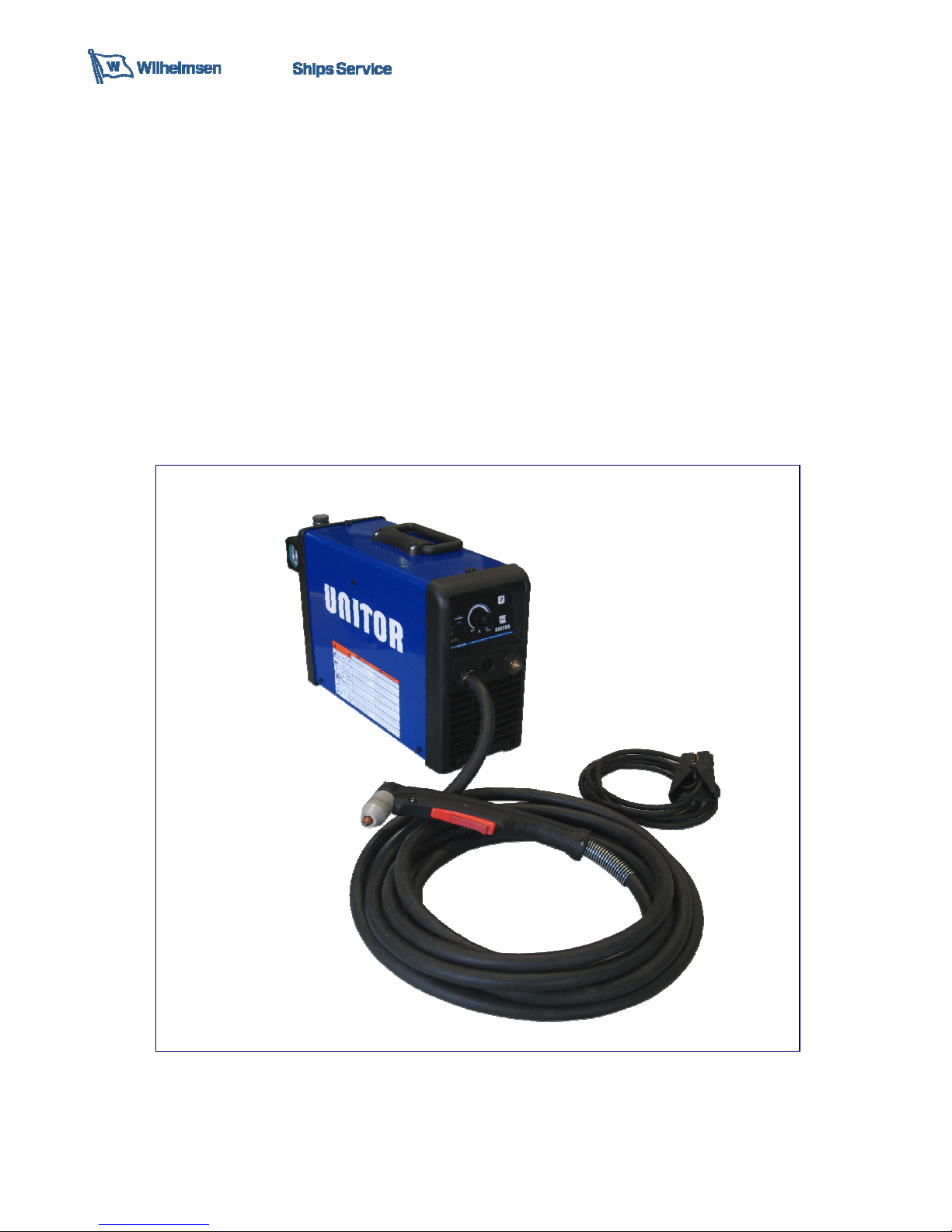
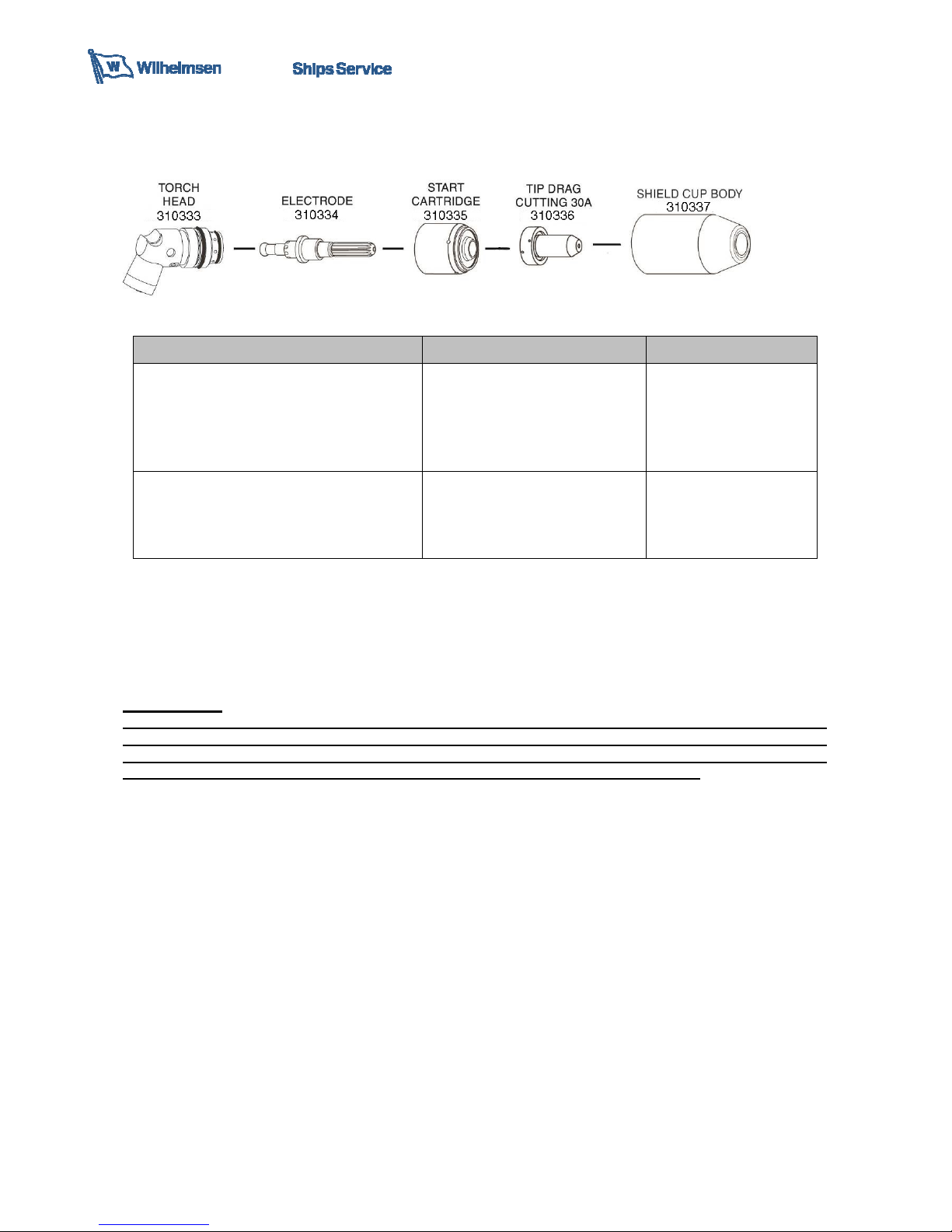
Wilhelmsen UNITOR UPC 310 ML User manual

01
Instruction manual
UPC 310 ML
Air Plasma Cutter

02
Revision summary
Rev.
No.
Version
Date issued
00 6938700000 April 18, 2018

03
CONTENTS
1.Safety instructions
2.Technical data
3.Installation
4.Operating instructions
5.Torch parts
6.Maintenance
7.Trouble shooting
8.Cutting/thickness characteristics
9.Wiring diagram
10.Parts list
DELIVERY
UPC-310ML Air Plasma Cutter 192-310331 delivery consist of:
1 Machine supply complete with 3,5m primary cable 2+G x 2,5mm2
2 Torch with 6m cable (connected directly to the machine)
3 Return clamp with 6m cable with Dix25
4 Initial supply consumables kit of 2 x Electrode, 2 x Tip Drag, 1 x Cartridge
5 Air regulator with filter and water separator mounted on the machine
6 User instruction manual
Remarks:
Air hose is not supplied.
Minimum diameter of the air hose should be 9mm – 3/8”.
In case you use an extension cord, be sure that it is of an appropriate wire gauge for the cord length and
system voltage.
Primary Voltage
Cord size
Length
115 V
4mm
2
(1
2
AWG)
Up to 20m (65 feet
)
230 V
2,5mm
2
(1
4
AWG)
Up to 50m (164 feet)

04
1 SAFETY INSTRUCTIONS
ELECTRIC SHOCK CAN KILL
- Disconnect the power supply before working on the plasma
machine.
- Do not work with deteriorated cable sheaths.
- Do not touch bare electrical parts.
- Ensure that all the panels covering the plasma machine are firmly
secured in place when the machine is connected to the mains
supply.
- Insulate yourself from the work bench and from the floor (ground):
use insulating footwear and gloves.
- Keep gloves, footwear, clothes, the work area and this equipment
clean and dry.
PRESSURISED CONTAINERS CAN EXPLODE IF WELDED.
When working with a plasma machine:
- do not cut pressurised container.
- do not cut in environments containing explosive powders or
vapours.
THE RADIATIONS GENERATED BY THE WELDING ARC CAN
DAMAGE THE EYES AND CAUSE BURNING OF THE SKIN.
- Provide suitable protection for the eyes and body.
- It is indispensable for contact lens wearers to protect
themselves with suitable lenses and masks.
NOISE CAN DAMAGE YOUR HEARING.
- Protect yourself suitably to avoid hearing damage.
FUMES AND GASES CAN DAMAGE YOUR HEALTH.
- Keep your head out of the reach of fumes.
- Provide suitable ventilation of the work area.
- If the ventilation is not sufficient, use an exhaust system that sucks from the bottom.
HEAT, SPLASHES OF MOLTEN METAL AND SPARKS CAN CAUSE FIRES.
- Do not cut near inflammable materials.
- Avoid having any type of fuel with you such as cigarette lighters or matches.
- The cutting sparks can cause burns. Keep the tip of the electrode far from your body and from other
persons.
PREVENTION OF ELECTRIC SHOCKS
Take the following precautions when working with a plasma machine:
- keep yourself and your clothes clean.
- do not be in contact with damp or wet parts when working with the plasma machine.
- maintain suitable insulation against electric shock. If the operator has to work in a damp environment, he
must take extreme care and wear insulating footwear and gloves.
- check the machine power cable frequently: it must be free from damage to the insulation. BARE CABLES
ARE DANGEROUS. Do not use the machine if the power cable is damaged; it must be replaced
immediately.
- if it is necessary to open the machine, first disconnect the power supply. Wait 5 minutes to allow the
capacitors to discharge. Failure to take this precaution may expose the operator to dangerous risks of
electric shock.
- never work with the plasma machine if the protective cover is not in place.
- ensure that the earth connection of the power supply cable is perfectly efficient.
This machine has been designed for use in a professional and industrial environment. For other types of
application contact the manufacturer. If electromagnetic disturbances are found it is the responsibility of
the machine user to solve the problem with the technical assistance of the manufacturer.
It is forbidden for people with PACEMAKERS to use or come near the machine.

05
PREVENTION OF BURNS
To protect your eyes and skin from burns and ultraviolet rays:
- wear dark glasses. Wear suitable clothing, gloves and footwear.
- use masks with closed sides, having lenses and protective glass according to standards (degree of
protection DIN 10).
- warn people in the vicinity not to look directly at the arc.
PREVENTION OF FIRE
Plasma cutting produces splashes of molten metal.
Take the following precautions to prevent fire:
- ensure that there is a fire extinguisher in the welding area.
- remove all inflammable material from the immediate vicinity of the welding area.
- cool the cut material or let it cool before touching it or putting it in contact with combustible material
- never use the machine for cutting containers of potentially inflammable material. These containers must be
completely cleaned before they are cut.
- ventilate the potentially inflammable area before using the machine.
- do not use the machine in atmospheres containing high concentrations of powders, inflammable gases or
combustible vapours.
2 TECHNICAL DATA
Power supply 230V ±15% 1~50/60 Hz
115V +15%/-10% 1~50/60 Hz
Mains fuse minimum (Slow
blow)
230V: 16A
115V: 20A
Maximum power 230V: 2kVA
115V: 1,3kVA
Process power 86V – 15A
92V – 30A
Air supply
NB! Dry and oil free
5-5,5 bar
100 l/min
Duty cycle @ 40° 20% @30A
60% @ 18A
100% @ 16A
Power factor 0,99
Open circuit voltage 250V
Protection class IP 23
Environmental conditions Cutting: -10°C + 40°C
Transport and storage: -20°C + 55°C
Cooling Forced
Temperature class H
Dimensions L x W x H 430x160x350 mm
Weight 15,4 kg
Severance cut 230V: 12 mm
115V: 12 mm
Quality cut 230V: 10 mm
115V: 8 mm
Recommended cut 230V: 8 mm
115V: 6 mm

06
3 INSTALLATION
WARNING: This Class A equipment is not intended for use in residential locations where the electrical
power is provided by the public low-voltage supply system. There may be potential difficulties in ensuring
electromagnetic compatibility in those locations, due to conducted as well as radiated disturbances. This
equipment is complying with IEC 61000-3-12 and It can be connect to a public and private low voltage
system. The good operation of the machine is ensured by correct installation; you must therefore proceed as
follows:
- Position the machine in such a way that there is no obstacle to the air circulation ensured by the internal fan
since the internal components require suitable cooling.
- Ensure that the fan does not send deposits or dust into the machine.
- Avoid impacts, rubbing, and – absolutely no exposure to dripping water, excessive heat sources, or any
abnormal situations.
CONNECTION
- Before making the electrical connections between the Inverter and the line switch, ensure that the switch is
turned off.
- The distribution panel must comply with the regulations in force in the country of use.
- The mains system must be of the industrial type.
- When using long extension cables, the core diameter section is increased as required for optimum performance.
- The power input supply socket must have a suitable switch provided with slow burning' type fuse(s).
- In the event of damage to the power cable, replacement or repair must be performed by a qualified person at an
approved service centre.
EARTHING
- To ensure user protection the Inverter must by law
be correctly connected to the earth system
(INTERNATIONAL SAFETY REGULATIONS).
- It is necessary to provide good earthing by means of
the yellow-green wire in the power cable, in order to
avoid discharges due to accidental contacts with
earthed objects.
- The chassis (which is conductive) is electrically
connected with the earth wire; if the equipment is not
suitably connected to earth it may cause electric
shocks which are dangerous to the user and those
nearby.
PNEUMATIC CIRCUIT CONNECTION:
The machine uses compressed air for plasma cutting. Any cylinder of compressed air may therefore be
used, or air from a compressor. The air must be free from polluting particles, such as oil or other
contaminating agents. A pressure regulator is provided to ensure the correct air flow rate on the torch.
KEY:
1– Air filter
2– Reducer (pressure regulator)
3– Pressure gauge
4– Pressure switch
5– Solenoid valves
A pressure between 5 bar and 5.5 bar must be applied to the air filter located on the rear panel of the
machine (100l/min). The pressure must not exceed 6 bar. The pressure regulator 1 is set by the
manufacturer at 4.8 bar. Check the pressure by pressing the Air Test button on the front panel and check
that the pressure gauge gives a reading of 4.8 bar. If necessary to the correct pressure by turning the knob
on the pressure regulator.
A pressure switch (4) in the machine will stop operation if the pressure at output of the reducer (2) is below 3
bar, which is minimum to guarantee operation.

07
4 OPERATING INSTRUCTIONS
Place machine as far away from where cutting takes place as possible. Use all of the 6m torch length. This is
to prevent the fumes produced by cutting from being sucked into machine by the cooling fans through the
front and side ventilation openings.
BEFORE CUTTING
The operator may start up the machine only after having read and understood all parts of this manual.
Depending on the type of cut to be performed he must follow the work phases described below.
WARNING! A preflow of 2 seconds after pressing the torch button to alert the operator of the
imminent start of the pilot arc.
1. Ensure that the work environment and your clothing satisfy the safety requirements described.
2. Position the unit in a place where there is no obstruction to air circulation.
3. Connect the unit to a suitable power socket (an earthed socket is obligatory).
4. Connect the compressed air pipe to the air filter on the rear panel.
5. Ensure that there is no water in the air filter. If necessary, empty the filter.
NOTE! Air filter is a semi-automatic drain. Semi-automatic drain operates when the air line is
depressurised. When the filter is pressurised, the drain can still operate manually by pushing the
tube in the filter, which then protrudes outside the filter bowl.
6. Return clamp must be clamped into the work piece or cutting table. The area must be free from oil, paint
and rust. Connect only to the main part of the work piece; do not connect to the part to be cut off.
FRONT PANEL DESCRIPTION
1 Air presence LED
2 Reset Protection alarm LED
3 Excess temperature LED
4 Welding enabled LED
5 Machine Live LED
6 Cutting current regulation
7 Air test button
8 RESET button

08
For the number reference below, refer to the Front Panel Description:
1.Turn the switch on the back panel to ON position.
2.The green led (5) will light up (Unit live).
3.The green led (1) will light up to indicate the presence of compressed air in the air circuit.
1.The red led (2) is illuminated and the unit is now in STAND-BY.
2.Set the output current (6) to a suitable value for the thickness that is to be cut. for thin materials reduced
output may be required to obtain a smooth and neat cut.
3.Before cutting, press the RESET button (8). The red led (2) is now off and you are ready to cut. If
the RESET button is not pressed the unit will remain on STAND-BY mode.
THIS IS A SAFETY DEVICE!
1.The Inverter is now ready for work. When you want to start, position the torch on the work-piece to be cut
and slide the trigger release toward the back of the torch and press the trigger. An air preflow of 2 seconds
will come before the pilot arc starts.
2.The arc is transferred to the work-piece and cutting will start. Move the torch in the desired direction at a
speed that ensures a good cutting quality.
3.When the cut is finished, release the torch trigger to stop the arc.
4.Air will continue to flow out for 15 seconds to cool the torch parts.

09
CUTTING TECHNIQUE
For best performance and life expectancy, always use
the correct and original parts for cutting torch.
1.Install the cutting tip and set the output current.
2.Hold the torch away from your body.
3.Slede the trigger release toward the back of the torch
handle while simultaneously squeezing the trigger. This
will activate a pre-flow of air foe 2 seconds before the
pilot arc is turned on followed by the plasma arc.
4.Start moving the torch across the work piece and
observe that the arc penetrate the work piece.
5.when cutting is established pull the torch slowly across
the surface of the work piece.
6.pause briefly at the and of the cut before releasing the
trigger.
7.The plasma arc goes out immediately. Air continue to
flow 15 seconds.
FOR PIERCING HOLES
With UPC-310ML you can pierce metal with thickness
up to 10mm.
1. Rest the torch tip lightly on the work piece at 45 deg.
Angle.
2. Press trigger on the torch handle. Air will flow for 2
seconds before pilot arc strikes.
3. When the plasma arc is established, slowly and one
smooth movement straighten the torch back to 90 deg.
Angle ensuring the arc penetrate the work piece.
4. Start moving the torch across the work piece and
observe that the arc continue to penetrate.

10
5 TORCH PARTS
DESCRIPTION PRODUCT NUMBER COMMENTS
TORCH HEAD FOR UPC-310ML
ELECTRODE FOR UPC-310ML
START CARTRIDGE FOR UPC-310ML
TIP DRAG CUTTING FOR UPC-310ML
SHIELD CUP BODY FOR UPC-310ML
TORCH WITH 6M CABLE FOR UPC-310ML
310333
310334
310335
310336
310337
310332
1 PCS
5 PCS
1 PCS
5 PCS
1 PCS
1 PCS
CONSUMABLE KIT FOR UPC-310ML
310338
ELECTRODE 5 PCS
TIP DRAG CUTTING 5 PCS
START CARTRIDGE 1 PCS
SHIELD CUP BODY 1 PCS
6 MANTAINANCE
This section describes basic maintenance procedures performable by operating personnel. No other
adjustments or repairs are to be attempted by other than properly trained personnel.
WARNING
Disconnect primary power at the source before disassembling the power supply, torch, or torch
leads. Frequently review the Important Safety Precautions at the front of this manual. Be sure the
operator is equipped with proper gloves, clothing, eye and ear protection. Make sure no part of the
operator’s body comes into contact with the workpiece while the torch is activated.
DAILY INSPECTION AND REPLACEMENT CONSUMABLE TORCH PARTS
Inspect and, if necessary, change the torch consumable parts. Electrode and nozzle must be changed at
regular intervals, as a general guideline after 3 hours continues use, after 200 starts or about 75m cut at
500mm/min - 30A. Replace the nozzle if the opening is deformed or clearly oversized. Failure to replace
worn nozzle or electrode in time will dramatically reduce the cutting capacity and eventually ruin the torch.
Carefully inspect the hose assembly and torch body with regard to any leak or damage.
NOTE
The shield cup holds the tip and the starter cartridge shield cup in place. Position the torch with the shield
cup facing out when the cup is removed.
NOTE
Slag build-up on the shield cup that cannot be removed may affect the performance of the system.
1. Unscrew and remove the shield cup from the torch
2. Inspect the cup for damage. Wipe it clean or replace if damaged
3. Removed the tip. Check for excessive wear (indicated by an elongated or oversize orifice, see images).
Clean or replace the tip if necessary.
4. Remove the starter cartridge. Check for excessive wear plugged gas holes, or discolouration. Check the

11
lower end fittings for free motion. Replace if necessary.
5. Pull the electrode straight out of the torch head. Check the face of the electrode for excessive wear. Refer
to the following figure.
6. Re-install the electrode by pushing it straight into the torch head until it clicks.
7. Re-install the desired starter cartridge and tip into the torch head
8. Hand tighten the shield cup until it is seated on the torch head. If resistance is felt when installing the cup,
check the threads before proceeding.
EVERY 3 TO 6 MONTHS
AIR CLEAN (DRY AIR) THE INTERNAL PART OF THE PLASMA MACHINE
Before cleaning the inside of the machine, it is obligatory to FIRST follow the WARNINGS described
previously and to proceed as follows:
1- Remove the casing, slackening the side screws;
2- Remove all traces of dust from the internal parts of the machine by means of a jet of dry compressed air at
a pressure no higher than 3 bar;
3- Visually check all the electrical connections, ensuring that the screws and nuts are well secured;
4- Visually check the state of all the components: replace any deteriorated components;
5- Put back the casing, tightening the side screws.
7 TROUBLESHOOTING
CONSUMABLE PARTS CHECK FUNCTION
The machine is equipped with automatic control of the state of the consumable parts.
Once the consumable (tip and electrode) wears out, the machine “LED” as shown in the picture will be
flashing for 3 seconds during the end of the cutting process. It is advisable to replace the consumable (tip
and electrode).
Failure to replace worn nozzle or electrode in time will dramatically reduce the cutting capacity and
eventually ruin the torch.

12
DUTY CYCLE AND EXCESSIVE TEMPERATURE
The Led indicator light (3) blink:
1. This is indicating the unit has exceeded the Duty Cycle.
The duty cycle is the percentage of use of the welding machine in 10 minutes
which the operator must respect to avoid the power supply output blocking
due to exceeding working temperature. If the machine goes into excessive
temperature protection mode:
2. It is necessary to wait about 10 minutes before resuming cutting.
3. Check the data plate on the unit or on see section TECHNICAL DATA in
the Operating Manual for duty cycle.
4. In the event the working condition are conforming to the specification on the
Technical Data Plate, but still the led (3) is on, this is an indication that one of
the PC Boards is possibly faulty. See service instruction section/manual.
DISPOSAL OF ELECTRICAL AND ELECTRONIC EQUIPMENT
Do not dispose of electrical equipment together with normal waste! In observance of
European Directive 2012/19/EU on Waste Electrical and Electronic Equipment and its
implementation in accordance with national law, electrical equipment that has reached the
end of its life must be collected separately and returned to an environmentally compatible
recycling facility. As the owner of the equipment, you should get information on approved
collection systems from our local representative. By applying this European Directive, you will
improve the environment and human health!
IN CASE OF MALFUNCTIONS, REQUEST ASSISTANCE FROM QUALIFIED PERSONNEL.
Continuous cutting
Cut
6 minutes
Wait 4
minutes

13
8. CUTTING / THICKNESS CHARACTERISTICS
0
100
200
300
400
500
600
700
800
900
1000
1100
1200
1300
1400
1500
0 1 2 3 4 5 6 7 8 9 10 11 12 13 14 15 16 17 18
Cutting speed (mm/min)
Thickness (mm)
Characteristics Thickness/ Cutting speed PLASMA 30
I2 = 230V - 30A 1torch SL100 I2 = 115V - 25A 1torch SL100
Fe C
Pressure = 4,8 bar
Flow = 90 l/min
230V 1-Phase, 30A
115V 1-Phase, 25A
Thickness Cutting Speed Note* Thickness Cutting Speed Note*
(mm) (mm/min) (mm) (mm/min)
12 100 Sever 12 50 Sever
10 200 Quality 10 100
8 400 Reccomended
8 250 Quality
6 850 6 550 Reccomended
4 1300 4 1050
*Recommended = Quality cut manually handle (around 500 mm/min)
Quality = Quality cut mechanized handle (less then 300mm/min)
Sever = Maximum achievable cut NOT quality
Piercing
(mm)
10

14
9. WIRING DIAGRAM

15
10. PARTS LIST
S/N DESCRIPTION PRODUCT
NUMBER
S/N DESCRIPTION PRODUCT
NUMBER
1
2
3
4
5
6
7
8
9
10
11
12
13
14
15
16
17
18
19
20
21
_
Handle
Cover
Panel
Switch
Regulating filter support
Regulating filter
Manometer
Power cable
Coupling
Pressure switch
Solenoid valve
Gas pipe
Cable relief
Panel
Fan support
Fan
PCB pilot exchange
Base
Fan
Cable relief
Ground cable
Return Clamp with Dix 25 Con.
66103400
620576U0
620357U0
64774000
620297R0
63055000
63053000
64432000
63513000
64032000
64393000
-
66078500
6608130L
620359U0
61133100
61223600
620293U0
61133100
66078500
60155500
633164
22
23
24
25
26
27
28
29
30
31
32
33
34
35
36
37
_
_
_
_
_
_
Knob
Front label
Front panel support
Potentiometer
PCB Front panel
XL out
Power transformer
Intermediate panel
XL PFC
Crosspiece up
Inverter PCB
Thermostat 60°
NTC 10K
Crosspiece lower
Grommet
Torch coupling support
Quick coupling for air inlet M.
Quick coupling for air inlet F.
Quick coupling 20UPM ¼” MPT
Quick coupling 30USH 3/8” Hose
Air hose 3/8”
Hose clamp 3/8”
66046700
66139800
620356U0
61107400
61223800
61247800
61236300
620461U0
61186500
620335R0
61223500
65023400
61382100
620358R0
66072000
6203550U
63008000
63669000
191874
191684
671750 (per meter)
729443 (pck of
10pcs)

16
DECLARATION OF CONFORMITY
According to
The Low Voltage Directive 2014/35/EU
The EMC Directive 2014/30/EU
The RoHS Directive 2011/65/EU
Type of equipment
Plasma equipment
Type of designation
601453000L – UPC310 MULTI-LINK
Brand name or trade mark
UNITOR
Manufacturer or his authorized representatives established within the EEA:
Name, address, phone, website:
STEL s.r.l
Via Del Progresso 59; 36020 Castegnero – Vicenza
Italy
Tel +39-0444-639525 Fax +39-0444-639682 www.stelgroup.it
The following harmonized standard in force within the EEA has been used in the design:
EN 60974-1:2012 Ed.4, Arc welding equipment – Part 1: Welding power sources
EN 60974-10:2014 Ed.3, Arc welding equipment – Part 10: Electromagnetic compatibility (EMC)
EN 61000-3-12, Arc welding equipment – Part 10: Electromagnetic compatibility (EMC) requirements
Additional information: Restrictive use, Class A equipment, intended for use in locations other than
residential.
By signing this document, the undersigned declares as manufacturer, or the manufacturer’s authorized
representative established within EEA, that the equipment in question complies with the safety requirements
stated above.
Date Signature Position
27-01-2017 Andrea Barocco General Manager

17
Table of contents
Other Wilhelmsen Welding System manuals
Popular Welding System manuals by other brands

Worldwel
Worldwel Longrun LD Series Operation manual

Lincoln Electric
Lincoln Electric Ranger 305D CE Operator's manual

Craftsman
Craftsman ARC WELDER user guide

STAMOS
STAMOS Soldering S-LS-18 Basic user manual

Longevity
Longevity STICKWELD 140STL operating manual

P.Lindberg
P.Lindberg Extreme 160III Original manual

Lincoln Electric
Lincoln Electric IDEALARK RSR 375-I Operator's manual

Lincoln Electric
Lincoln Electric MAGNUM X-TRACTOR 1GX Operator's manual

STAMOS
STAMOS S-LS-69 user manual

WilTec
WilTec TIG180 Operation manual

SHARKS
SHARKS MMA-160A Instruction for operation and maintenance

iWeld
iWeld GORILLA MICROFORCE 120 VRD user manual