Wilhelmsen UPC-85ML Programming manual

01
Trouble Shooting
Manual
UPC-85ML

02
CAUTION!
Turn OFF and disconnect input power before working on the machine
Wait discharge of capacitors (minimum 2 minutes) and be sure voltage is
near zero before touching any parts.
PROBLEM
CASE
SOLUTION
The Machine does not switch on.
Power supply off.
Input cable damaged.
Main switch damaged.
Step 1
-Check the incoming power supply
are correct. (230V 1Phase or 400-
440V 3Phase).
Step 2
-Check the primary cable and plug
(PICTURE 1).
Step 3
-Check the main switch on the
power source S1 and the wires to
the switch (PICTURE 1).
Step 4
- Check the wires from the main
switch to the line filter board PCB
1 (PICTURE 16) and the cable
connection between the Flyback
board PCB 11 (J2) and the front
logic board PCB 10 (J1)
(PICTURE 17).
Main Switch turned On, all Led Off.
No display on the front panel.
Cooling fan does not work.
Step 1
-Switch off the machine,
disconnect the plug.
Make sure the flat cable that
connects the Flyback board PCB
11 (J2) and the front logic board
PCB 10 (J1) is inserted correctly
(PICTURE 17).
Step 2
Check the power supply cable
(PICTURE 1) If there is continuity
with a diode tester, continue to
check on the Flyback board
PCB11 (PICTURE 22).
Step 3
If Step 2 are correct, replace
PCB10. If reading are wrong,
replace both PCB 8-9 and PCB11.
When powering up the plasma cutter
machine, the circuit breaker trips.
Faulty PCB.
Step 1
-Switch off the machine,
disconnect the plug.
Check:
Primary IGBT Inverter
(PICTURE 5 )
Secondary Diode Inverter

03
Input cable damaged.
(PICTURE 6)
Input bridge rectifier (PICTURE
4);
Boost system (PICTURE 11)
. They are faulty and to be
replace.
Step 2
-Check the input cable and plug
(PICTURE 1).
The pilot arc doesn’t start.
-Red led (reset) on.
-Incorrect compressed air
setting or insufficient
compressed air.
-Faulty PCB. To determine
conduct the following checks.
Pilot arc power switch (K1)
damaged.
Step 1
-Press the reset button to be
ready to cut (see instructions
manual).
-Check the torch, it has to be
mounted in right way (PICTURE
19).
-Check the O-Ring (PICTURE
2).
-Check the consumables. If they
are in the wrong position the led
won’t turn off (PICTURE 20).
-Check for incoming air
pressure. It must be greater than
3 bar.
-Chek the pressure switch
(PICTURE 23)
Step 2
-Check the input compressed air
(PICTURE 12).
Step 3
-Switch off the machine,
disconnect the plug.
Check:
Primary IGBT Inverter
(PICTURE 5)
Secondary Diode Inverter
(PICTURE 6)
Input bridge rectifier (PICTURE
4)
Boost power board (PICTURE
11)
They are faulty and to be replace.
Step 4
-Check pilot power SWITCH K1
(PICTURE 14). Replace if
reading are incorrect.

04
The inductive value of the
reading is >1 ohm.
Step 5
-The Power transformer must be
replace if reading are > 1ohm.
(PICTURE 10)
Cutting performance deteriorating.
-Consumable (tip and
electrode) wears out.
-Cut speed not correct.
-Incorrect compressed air
setting or insufficient
compressed air.
Step 1
Check the consumables, try to
substitute with new ones
(PICTURE 18).
Step 2
-Check the speed, see the
“cutting tables” in the instructions
manual pg 19.
Step 3
-Check the input compressed air
(PICTURE 12).
Nothing happen when you press the
trigger or the pilot arc turns off quickly.
-Return cable defective or not
correctly connected.
-Pilot arc power switch K1
damaged.
-Faulty PCB. To determine
conduct the following checks.
-Front Logic board
malfunction
-Control Lem Board
malfunction
Step 1
-Check the ground cable to the
power source for damage
(PICTURE 3). Check that return
clamp are clamp close to the work
piece for good continuity.
-Check for any loose connections
inside the power source.
Step 2
-Check pilot arc PCB (PICTURE
14). ). Replace if reading are
incorrect.
Step 3
-Switch off the machine,
disconnect the plug.
Check:
Primary Inverter IGBT
(PICTURE 5)
Secondary Inverter Diode
(PICTURE 6 )
Input bridge rectifier (PICTURE
4)
Boost system (PICTURE 11)
They are faulty and to be replace.
Step 4
If above checks are all correct: -
The logic board PCB10 is faulty
and to be replace.
The control Lem board PCB13 is
faulty and to be replace.

05
Thermal protection LED blinking
HT1 or HT3 message
HT7 message
PF1 message
HT0 permanent message
-Exceed duty cycle.
Indicates over temperature
PC8 inverter Module NTC1 or
NTC2.
-Exceed duty cycle.
Indicates over temperature
secondary power rectifier
diodes NTC5.
-Exceed duty cycle.
Indicates over temperature
on Boost converter (NTC3 or
NTC4)
-The thermal protection
indication appear frequently.
-Thermal switch faulty.
Indicates malfunction of
thermistors protection.
Step 1
-Let the machine cool down.
After 4 minutes the message
disappears and it is possible to
start cutting again.
Step 2
-Let the machine cool down.
After 4 minutes the message
disappears and it is possible to
start cutting again.
Step 3
-Let the machine cool down.
After 4 minutes the message
disappears and it is possible to
start cutting again.
Step 4
-Check FAN1 and FAN2
(PICTURE 13). If reading are
correct, to be replace the Fans.
If reading are incorrect to be
replace the logic board PCB10.
Step 3
- Switch off the machine and
disconnect the plug.
-Check:
NTC 1 Sensor thermal protection
IGBT module 1 (PICTURE 7)
NTC 2 Sensor thermal protection
IGBT module 2(PICTURE 7)
NTC 3 Sensor thermal protection
Boost module 1 (PICTURE 8)
NTC 4 Sensor thermal protection
Boost module 2 (PICTURE 8)
NTC 5 Sensor thermal protection
Secondary diode (PICTURE 9)
If reading are incorrect, to be
replace:
-Primary inverter board (PCB8) for
NTC 1 abd 2.

06
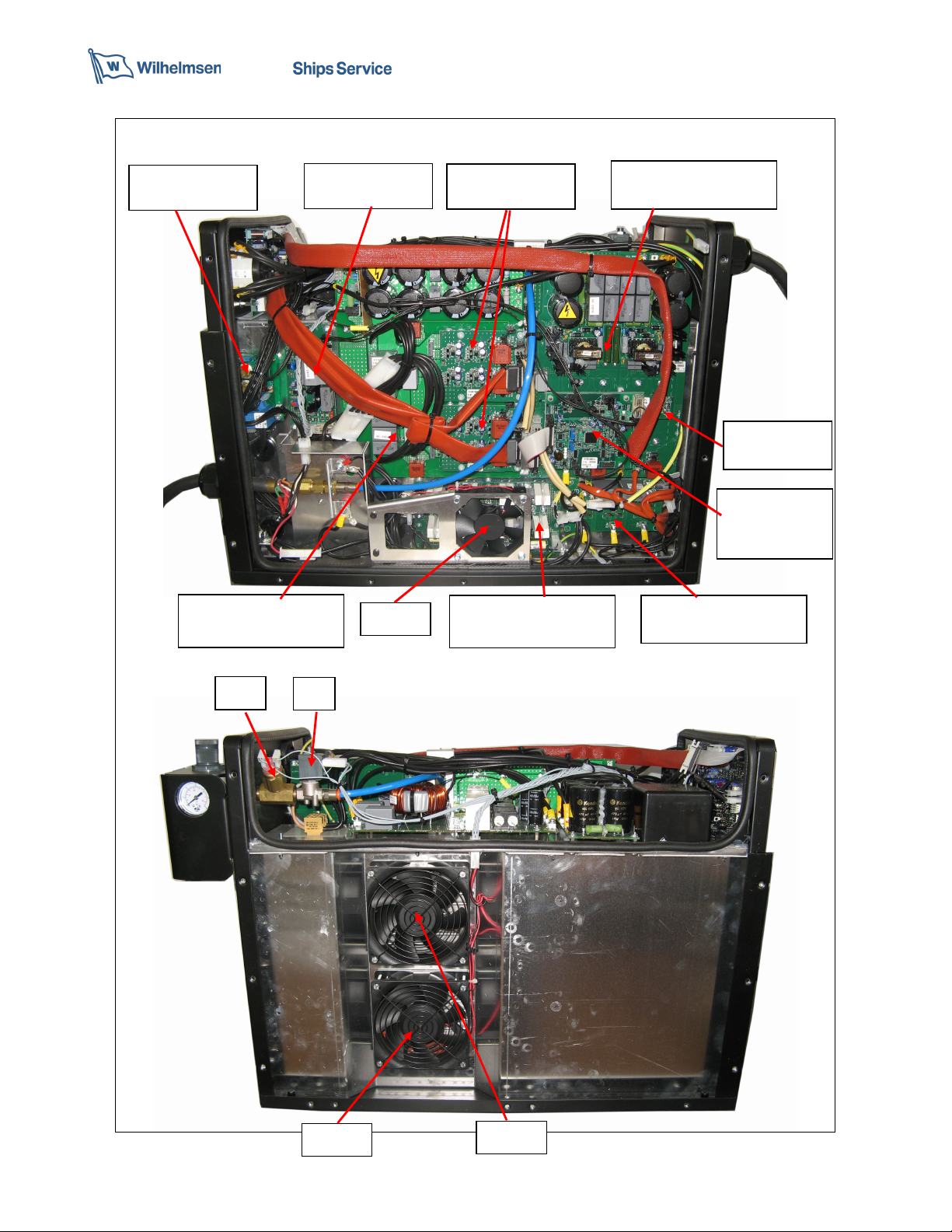
-Boost power board (PCB5) for
NTC 3 and 4.
- The sensor under the secondary
inverter board for NTC 5.
During cutting, the Circuit Breaker trip.
Make sure the cutting current
does not require input power
greater than what supplied by
the line or the fuse is too low.
Check the fuse size.
230V 1Ph: 25A
400V 3Ph: 16A
440V 3Ph: 16A
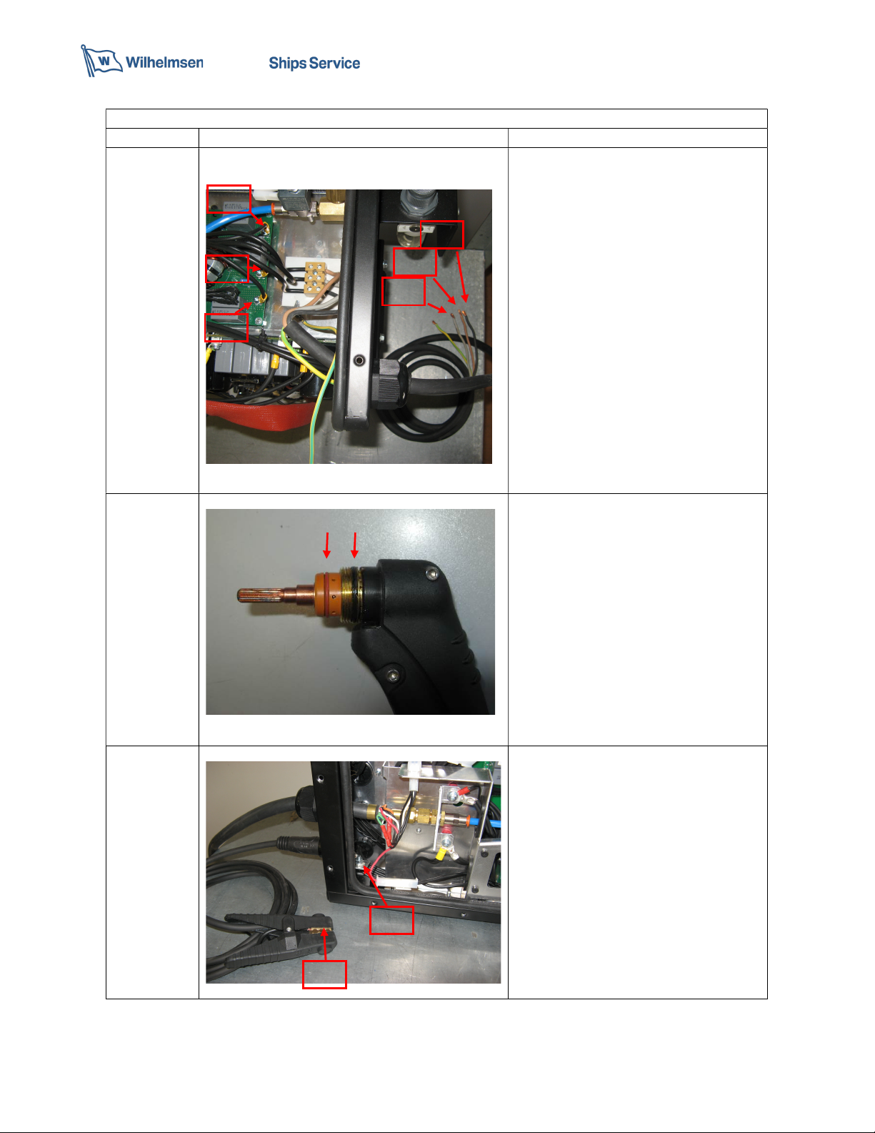
No compressed air output.
Solenoid valve damaged.
Front panel logic board
PCB10 faulty.
-When you push test air, check
the supply voltage of EV
(PICTURE 15).
If the voltage is present and no air
output the Solenoid valve must be
replace.
-If above checks are all correct.
The logic board PCB10 is faulty
and to be replace.
Always compressed air out when I turn on
the machine
Front panel logic board
PCB10 faulty.
-If above checks are all correct.
The logic board PCB10 is faulty
and to be replace.
Maximum output current always 60A
Phase failure.
The generator is working in
single phase.
Check the input of the 3 phases.
The arc does not transfer to the workpiece Ground clamp problem
-Clean the area where the ground
clamp contacts the workpiece to
ensure a good metal-to-metal
contact.
-Inspect the ground clamp for
damage and rapair it if necessary.
-Move the torch closer the
workpiece and fire the torch again.
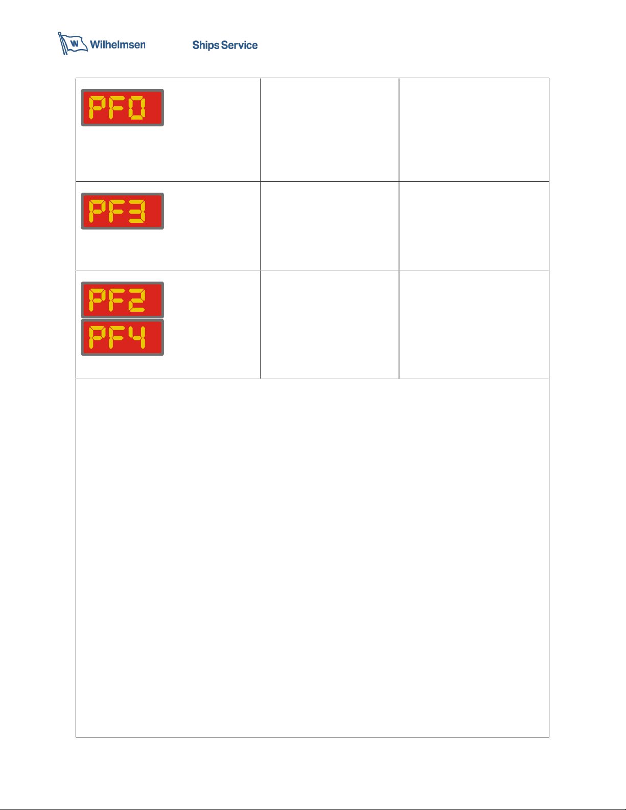
Error message
TRI message
Indicates that machine has
been turned on while pressing
torch switch.
Release the trigger and restart the
power supply.
Error message
PIP message
Indicates that the
consumables are not correctly
mounted.
Check the correct assembly of
consumables (PICTURE 20).

07
Error messages
PF0 permanent message
Indicates mains supply
problem.
Switch off the generator and
check the power supply.
• Verify that the power cord is
plugged into the receptacle.
• Verify that the line voltage is not
too low (more than 10% below
the rated voltage 230V).
Error messages
PF3 permanent message
Indicates Boost inductance
malfunction.
Switch off the machine,
disconnect the plug.
Check:
-the cable between PCB4 (J4) and
Boost Inductors.
If the connection is correct,
replace the boost inductance.
Error messages
PF2, PF4 permanent message
Indicates malfunction of
Boost system
Switch off the machine,
disconnect the plug and check
Boost system (PICTURE 11)

08
RIGHT SIDE
LEFT SIDE
Primary
Inverter
board PCB8
S1
FAN1 FAN2
PS1
Flyback board
PCB
11
Boost power board
PCB5
Power rectifier
board PCB2
Secondary Inverter
board PCB12
FAN3
LEM sensor
board PCB
13
Boost logic
control
board PCB4
Driver inverter
board PCB9
Driver boost
board PCB6

09
TOP
FRONT REAR
Logic board PCB10
Pilot arc power switch K1
Line filter boost board
PCB1
Bus DC board PCB7
Power transformer T1 Output inductance XL1 Boost inductance PCB3

10
EXPLANATION
PICTURE 1
Check the power supply cable and the
ON/OFF switch.
Disconnect the machine to the power
supply and switch on the main switch.
Check the continuity, with a diode tester,
between points A1-I1, A2-I2 and A3-I3.
If there is no continuity, you have to
check the single parts step by step.
-Check the power supply cable.
-Check the wires from the main switch to
the line filter
-Check the main switch.
-Check the wires from the main switch to
the line filter board PCB 1 (PICTURE 16).
PICTURE 2
Check the O-ring in correct position and
good condition.
PICTURE 3
Disconnect the machine to the power
supply.
Check the continuity, with a diode tester,
between points C1-D1.
If there is no continuity, you have to
replace ground cable.
A1
A
2
I
1
I2
D
1
C
1
A
3
I3

11
PICTURE 4
3-phase Input bridge rectifier (PCB3)
To check the Input bridge rectifier (all
three bridges PD1,PD2 and PD3), carry
out the following measurements with a
diode tester:
Pin Probe Pin Probe Measu
re
R+
RED
R
~
Black
‘OL’
R
-
RED
R
~
Black
>.42
R+
Black
R
~
RED
>.42
R
-
Black
R
~
RED
‘OL’
R~
R~
R+
R
-

12
PICTURE 5
For testing the IGBT module is
necessary remove the two Driver
inverter board (PCB9).
Primary inverter IGBT (PCB1)
To check the Primary inverter IGBT,
carry out the following measurements
with a diode tester:
Red Probe Black probe Measure
G
S
‘OL’
D S >0.9 / OL
G
D
‘OL’
S G ‘OL’
D
G
‘OL’
S
D
>0.4
N.B. Always replace the two Driver
inverter board together with the faulty
Inverter PCB.
GDS
GDS
GDS
GDS

13
PICTURE 6
Remove FAN3 support before operate
on the Secondary inverter PCB.
Secondary inverter DIODE (PCB12).
To check the Secondary Inverter Diode,
carry out the following measurements
with a diode tester:
Red Probe
Black probe
Measure
A
K
>
.
35
K
A
>1.7 /
‘OL’
If the diodes are faulty, remove the pcb
board and replace the isotop diodes.
A K
A K
K A
K A

14
PICTURE 7
-Check the value of NTC sensor IGBT
Module (PCB8) with the ohm-meter tester.
Normally reading should be 10KΩ @25°C.
PICTURE 8
-Check the value of NTC sensor Boost
module (PCB5) with the ohm-meter tester.
Normally reading should be 10KΩ @25°C.
NTC2
NTC1
NTC value
NTC4
NTC3
NTC value

15
PICTURE 9
-Check the value of NTC sensor
Secondary diode with the ohm-meter
tester. Normally reading should be 10KΩ
@25°C.
PICTURE 10
Power transformer.
Locate the connections between power
transformer and Primary inverter board
(PCB8).
Disconnect and measure between:
-Conn1 Pin 1-2 and Pin 3-4= > 0,4 ohm.
-Conn2 Pin 1-2 and Pin 3-4= > 0,4 ohm
Pin1
-
2
Pin3
-
4
NTC value

16
PICTURE 11
Step 1.
Check the correct indication of the LEDs
on the Logic contrl boost PCB4:
-DL1 illuminates.
-DL4 illuminates.
-DL5 Illuminates.
-DL6 blinks slowly.
-DL7 off.
Step 2.
Check the 24Vdc logic power supply voltage
Step 3.
Vbus.
Check the 730Vdc power supply voltage.
Step 3.
For testing the Boost IGBT module is
necessary remove the Driver boostboard
(PCB6).
Power boost board (PCB5)
To check the Primary inverter IGBT,
carry out the following measurements
with a diode tester:
Red Probe Black probe Measure
G
S
‘OL’
D
S
>0.9
/ OL
G
D
‘OL’
S
G
‘OL’
D G ‘OL’
S
D
>0.4
Red Probe
Black probe
Measure
A K >.35
K
A
‘OL’
DL1
DL4
DL5
DL6
DL7
24Vdc
SDG

17
N.B. Always replace the Driver boost
board together with the faulty Power
boost.
PICTURE 12
Make sure that the air pressure regulator
is setting at 4,8 bar.
SET PRESSURE
SDG
SDG
A
K

18
PICTURE 13
Check the motor fan:
-FAN1= pin1(+), pin2(-) = 24Vdc max
-FAN2= pin3(+), pin4(-) = 24Vdc max
Note: Fan on demand!
PICTURE 14
Pilot arc power switch (K1).
Remove the plastic cover protection.
Visual inspection to check the power
contacts.
Turn ON the machine and verify:
-during the pilot arc contacts are close;
-during the cut contacts are open.

19
PICTURE 15
Check the solenoid valve:
V= 15Vdc
PICTURE 16
Check the continuity of the cable, with a
diode tester, between the main switch and
the control board PCB 1.
PICTURE 17
Check the continuity of the cable, with a
diode tester, between the Flyback board
PCB 11 (J2) and the front logic board PCB
10 (J1) and are properly connected.
V

20
PICTURE 18
Photos comparison of new and worn
consumables.
PICTURE 19
E) 4pin connector:
-pin1/pin2= switch torch (white/green
cable)
-pin3/pin4= safety (black/orange cable)
F) 1pin connector= Pilot (red cable)
G) 9/16” coupling= compressed air.
E
F
G
Table of contents
Other Wilhelmsen Welding System manuals
Popular Welding System manuals by other brands

Spartus
Spartus MasterMIG 200PFC Synergy user manual

Saf-Fro
Saf-Fro PRESTOTIG 415DC Operator's manual

STAMOS
STAMOS 180B user manual

Televes
Televes Fusion splicer 232103 operating instructions

Lincoln Electric
Lincoln Electric POWER-ARC 4000 SVM103-A Service manual

Lincoln Electric
Lincoln Electric CV320-I operating manual