DINSEO DIX PI 3006.M PULS User manual

BA-0118
MIG/MAG / TIG Welding Power Source
SCHWEISSEN WELDING WELDINGSCHWEISSEN SCHWEISSEN
Keepinsecureareaforfuturereference!
Operations manual
DIX PI 3006.M PULS
DIX PI 4006.M PULS
DIX PI 4606.M PULS

2
Introduction
Thank you for buying our product.
In order to get the best performance out of the plant and ensure
the maximum lifespan of its parts, the use and maintenance
instructions contained in this manual must be read and strictly
complied with, as well as the safety instructions contained
in the relevant folder. If repairs to the plant are required, we
recommend that our clients contact our service centre work-
shops, as they have the necessary equipment and personnel
that are specifically trained and constantly updated.
All our welding power sources and equipment are constantly
developed and so changes may be made in terms of their con-
struction and features.
Description
MULTI-FUNCTION INVERTER WELDING POWER SOURCE
for MIG-MAG, MMA, and TIG WELDING
The multi-function equipments are characterised by cutting
edge, attractive design combined with latest generation inverter
technology and digital welding control. Innovative, technologi-
cally advanced, robust, and easy to use, they can be used for
very high quality MIG-MAG and Pulse MIG welding for all ma-
terials and especially stainless steel and aluminium, reducing
repeat work due to spray to a minimum, using electrodes, and
in TIG with “Lift” type ignition, and they represent the best so-
lution for all industrial fields and all specialist welding purposes
that call for high precision and repeatable results. These weld-
ing equipments, fitted with an innovative synergic digital control,
colour display, and the extraordinary software DIX ARC meet
the needs of those that wish to combine synergy with complete
control of all welding parameters.
They come in a version with a separate feeder (WF 793.M).
These are systems open to the future evolution of technology -
the control software can be kept up to date with the latest ver-
sions with the help of a personal computer.
Operating features
The main feature of the welding unit DIX PI 3006.M PULS,
DIX PI 4006.M PULS and DIX PI 4606.M PULS are:
• Metallic main structure with shockproof plastic front frames.
• Controls protected by a visor.
•
Spatter free exceptional welding characteristics in both MIG/
MAG, MIG Pulsed and MIG Dual Pulsed on any material and
with any gas.
•
High welding performance in both MMA and TIG by “Lift”
mode striking.
• Synergic digital control of all welding parameters, displayed
via the innovative colour display, also featuring the follow-
ing functions:
-
Allows less expert operators to regulate all welding param-
eters in a user-friendly way and extremely easily, choos-
ing the type of program on the basis of the material, wire
diameter, and gas used.
-
Innovative “DIX ARC” software for controlling all welding
parameters.
-
With the special MIG torches you can adjust the welding
parameters at a distance straight from the torch.
- BURN BACK control.At the end of each weld, in any con-
dition and with any material, the digital control ensures a
perfect wire cut, prevents the typical “wire globule” from
forming and ensures correct arc restriking.
-
WSC Wire start control. This arc striking control device pre-
vents wire from sticking to the workpiece or torch nozzle
and ensures precise and smooth arc striking, particularly
when welding aluminium.
-
Welding parameters that are controlled digitally by a micro-
processor, are monitored and modified in just a few sec-
onds, maintaining a consistently precise and stable arc as
the welding conditions continue to vary due to the move-
ment of the torch and the irregularities of the parts to be
welded.
Introduction 2
Description 2
Operating features 2
Technical data 3
Usage limits (IEC 60974-1) 3
How to lift up the system 3
Opening the packaging 4
Installation and connections 4
Connection to the electrical supply 4
Usage norms 4
MIG-MAG / PULSE MIG / DOUBLE PULSE MIG
Welding 5
Spot welding 7
Interval welding 7
Aluminium welding 7
Electrode welding (MMA) 7
TIG welding with “Lift” 8
Maintenance 8
Optional 8
The pointing out of any difficulties and their elimination9
Replacing the digital interface PCB 9
Wiring diagram 10
Key to the electrical diagram 11
Colour key 11
Meaning of graphic symbols on welding power
source 12
Copyright © 2018 DINSE G.m.b.H., Hamburg.
These instructions or excerpts there of shall not be duplicated, transla-
ted or reproduced, nor shall they be stored, processed, transmitted or
distributed by any electronic means without the prior written permission
of DINSE G.m.b.H.
DINSE G.m.b.H.
Tarpen 36 • D-22419 Hamburg
Tel. +49 (0)40 658 75-0
Fax +49 (0)40 658 75-200

3
-
Exclusive SWS “Smart Welding Stop” system at the end of
TIG welding. Lifting up the torch without switching off the
arc will introduce a slope down and it will switch off auto-
matically.
-
“Energy Saving” function to operate the power source cool-
ing fan and the torch water cooling only when necessary.
- Auto-diagnostic feature for trouble shooting.
- Password-controlled total or partial equipment access.
• High electrical performance resulting in a reduction in ener-
gy consumption.
•
Remote parameter adjustment directly from WF 793.M feed-
er.
Technical data
The general technical data of the system are summarized in
table 1.
Usage limits (IEC 60974-1)
The use of a welder is typically discontinuous, in that it is made
up of effective work periods (welding) and rest periods (for the
positioning of parts, the replacement of wire and underflush-
ing operations etc. This welder is dimensioned to supply a I
2
max nominal current in complete safety for a period of work of
40/50% of the total usage time. The regulations in force estab-
lish the total usage time to be 10 minutes. The work cycle is
considered to be 40/50% of this period of time. Exceeding the
work cycle allowed could cause a trip switch to trip, which pro-
tects the components inside the welding power source against
dangerous overheating.After several minutes the overheat cut-
off rearms automatically and the welder is ready foruse again.
How to lift up the system
Strap the system safely and securely in the slings working from
the bottom, then lift up from the ground.
This welding power source has a robust handle built into the
frame for moving the equipment.
NOTE: These hoisting and transportation devices conform to
European standards. Do not use other hoisting and transpor-
tation systems.
Table 1
Model DIX PI 3006.M PULS DIX PI 4006.M PULS DIX PI 4606.M PULS
MIG-MAG welding
Three-phase input 50/60 Hz V400 ± 20% 400 ± 20% 400 ± 20%
Mains supply: Zmax Ω0,037 0,028 0,017
Input power @ I2Max kVA 18,8 25,5 32
Delayed fuse (I2@ 60%) A25 30 40
Power factor / cosφ 0,64 / 0,99 0,66 / 0,99 0,66 / 0,99
Efficiency degree η0,83 0,86 0,89
Open circuit voltage V63 70 70
Current range A10 ÷ 330 10 ÷ 400 10÷500
Duty cycle @ 100% (40°C) A280 330 380
Duty cycle @ 60% (40°C) A300 370 460
Duty cycle @ X% (40°C) A330 (40%) 400 (50%) 500 (50%)
Wires diameter (*) mm 0,6 ÷ 1,2 (*) 0,6 ÷ 1,6 (*) 0,6 ÷ 1,6 (*)
N° rollers (*) 4 (*) 4 (*) 4 (*)
Power output of feeder motor (*) W100 (*) 100 (*) 100 (*)
Rated wire feeding speed (*) m/min 0,5 ÷ 25 (*) 0,5 ÷ 25 (*) 0,5 ÷ 25 (*)
Spool (*)
Diameter
Weight mm
kg Ø300 (*)
15 (*) Ø300 (*)
15 (*) Ø300 (*)
15 (*)
Standards IEC 60974-1 - IEC 60974-5 (*) - IEC 60974-10
Protection class IP 23 S IP 23 S IP 23 S
Insulation class HHH
Dimensions mm 660 - 515 - 290 660 - 515 - 290 660 - 515 - 290
Weight kg 35 40 44
(*) On the WF 793.M feeder, fitted separately.
WARNING: This equipment complies with EN//IEC 61000-3-12 provided that the maximum permissible system impedance Zmax is less than or
equal to 0,037 Ω DIX PI 3006.M PULS - 0,028 Ω DIX PI 4006.M PULS - 0,017 Ω DIX PI 4606.M PULS at the interface point between the user’s
supply and the public system. It is the responsibility of the installer or user of the equipment to ensure, by consultation with the distribution net-
work operator if necessary, that the equipment is connected only to a supply with maximum permissible system impedance Z
max
less than or
equal to 0,037 Ω DIX PI 3006.M PULS - 0,028 Ω DIX PI 4006.M PULS - 0,017 Ω DIX PI 4606.M PULS.
This system, tested according to EN/IEC 61000-3-3, meets the requirements of EN/IEC 61000-3-11.

4
Opening the packaging
The system essentially consists of:
•
DIX 3006.M PULS, DIX PI 4006.M PULS or
DIX PI 4606.M PULS weld unit.
• Separately:
- WF 793.M wire-feeder unit (supplied separately).
- MIG-MAG welding torch (optional).
-
Wire-feeder/welding power source interconnection cable
(supplied separately).
- Cooling modul for welding torch (optional).
- Trolley to carry it around (optional).
Perform the following operations on receiving the apparatus:
• Remove the welding power source and all accessories and
components from the packaging.
•
Check that the welding apparatus is in good condition; other-
wise immediately inform the retailer or distributor.
• Check that all the ventilation grilles are open and that there
is nothing to obstruct the correct air flow.
Installation and connections
The installation site for the system must be carefully chosen
in order to ensure its satisfactory and safe use. The user is re-
sponsible for the installation and use of the system in accord-
ance with the producer’s instructions contained in this manual.
Before installing the system the user must take into consider-
ation the potential electromagnetic problems in the work area.
In particular, we suggest that you should avoid installing the
system close to:
• Signalling, control and telephone cables.
• Radio and television transmitters and receivers.
• Computers and control and measurement instruments.
• Security and protection instruments.
Persons fitted with pace-makers, hearing aids and similar
equipment must consult their doctor before going near a weld-
ing power source in operation. The equipment’s installation
environment must comply to the protection level of the frame.
The welding unit is characterized by the following classes:
•
IP 23 S protection class indicates that the welding power
source can be used in both interior and exterior environ-
ments.
•
The “S” usage class indicates that the welding power source
can be employed in environments with a high risk of electri-
cal shocks.
This system is cooled by means of the forced circulation of air,
and must therefore be placed in such a way that the air may
be easily sucked in and expelled through the apertures made
in the frame.
Assemble the system in the following way:
• Assemble the trolley.
• Fixing the cooling unit to the trolley.
•
Fixing of the welding power source to the trolley and the cool-
ing unit (electrical and plumbing connections).
• Fitting the feeder unit to the welding power source.
• Connect up the welder to the mains.
• Connect up the wire-feeder/welding power source intercon-
nection cable.
• Connect up the welding cables.
Instructions for fitting the individual components / optional ex-
tras are contained in the relevant packaging.
Connection to the electrical supply
Connection of the welding power source to the user line
(electrical current) must be performed by qualified per-
sonnel.
Before connecting the welding power source to the mains
power supply, make sure that rated voltage and frequen-
cy correspond to those provided by the mains power sup-
ply and that the welding power source’s power switch is
turned to “O”.
Use the welder’s own plug to connect it up to the main pow-
er supply. Proceed as follows if you have to replace the plug:
•
3 conducting wires are needed for connecting the welding
power source to the supply.
•
The fourth, which is YELLOW GREEN in colour is used for
making the “GROUND” connection.
Connect a suitable load of normalised plug (3P+T) to the
power cable and provide for an electrical socket complete
with fuses or an automatic switch. The ground terminal
must be connected to the ground conducting wire (YEL-
LOW-GREEN) of the supply.
Table 2 shows the capacity values that are recommended for
fuses in the line with delays.
NOTE: Any extensions to the power cable must be of a suita-
ble diameter, and absolutely not of a smaller diameter than the
special cable supplied with the welding power source.
Usage norms
CONTROL APPARATUS (Fig. A)
Pos. 1 Control panel.
Pos. 2 Fast coupling positive polarity.
Pos. 3 Fast coupling negative polarity.
Pos. 4 Mains switch. In the “O” position the welder is off.
Pos. 5 Connector for connecting the interconnection cable
or auxiliary welding controls.
Pos. 6 Fast coupling reverse polarity.
Pos. 7 Connector for connecting the cooling system.
Pos. 8 Mains cable.
Table 2
Model DIX PI 3006.M PULS DIX PI 4006.M PULS DIX PI 4606.M PULS
MIG-MAG welding
Input power @ I2Max V18,8 25,5 32
Delayed fuse (I2@ 60%) A25 30 40
Duty cycle @ 50% (40°C) A330 (40% ED) 400 500
Mains cable
Length
Section m
mm² 4,0
4 × 2,5 4,5
4 × 4 4,5
4 × 6
Ground cable section mm² 50 50 70

5
MIG-MAG / PULSE MIG / DOUBLE
PULSE MIG Welding
To begin MIG-MAG / PULSE MIG / DOUBLE PULSE MIG weld-
ing, carry out the following tasks (with the welding power source
switched off).
1 - Connecting the gas hose and torch (Fig. B1-B2)
•
Connect the gas hose to the pressure reducer fitted on the
cylinder beforehand.
• Screw the torch onto the centralised connection on the front
panel of the feeder and connect the feed (blue) and return
(red) water hoses for cooling the torch to the respective (blue
and red) rapid couplings on the front panel of the feeder.
2A - Connecting the cables - Welding with a HAND
HELD TORCH SET as POSITIVE POLE (Fig. B1)
1) The feeder - welding power source connecting cable is
used to connect the welding power source to the feeder.
WARNING: Do not disconnect the wire-feeder until the
welding power source has been switched off.
Connect up the interconnection cables (power cable, an-
cillary wiring and gas tube) to the special attachments and
couplings shown in Fig. B1.
The delivery (blue coloured) and return (red coloured) wa-
ter tubes, used for cooling the torch of the welding power
source, are part of the interconnection cable and should
be connected as follows:
FIG. A
FIG. B1 2000FC15

6
•
Interconnection cable on welding power source side:
connect up tubes to their rapid couplings (blue and red
coloured) at the back of the coolant system.
• Wire feeder side connecting cable: connect the red and
blue pipes to their respective bulkhead grommets on the
rear panel of the feeder.
2) Connect up the earthing system cable to the rapid cou-
pling marked by a - (negative) symbol and then the rel-
evant ground clamps to the piece being welded or to its
support in an area free from rust, paint and grease. Using
particularly long earthing cables reduces the voltage and
causes some problems from increased resistance and in-
ductance of the cables that could cause faulty welding. Fol-
low instructions to avoid these problems:
•
Use earthing and extension cables with appropriate sec-
tion.
• Lay out the cables as a flat as possible to prevent them
from coiling up.
2B - Connecting the cables - Welding with a HAND
HELD TORCH SET as NEGATIVE POLE (Fig. B2)
1) Connect the welding power source - feeder connection ca-
ble using the extension cable in addition to invert the po-
larity (optional).
WARNING: Do not disconnect the wire-feeder until the
welding power source has been switched off.
Connect up the interconnection cables (power cable, an-
cillary wiring and gas tube) to the special attachments and
couplings shown in Fig. B2.
The delivery (blue coloured) and return (red coloured) wa-
ter tubes, used for cooling the torch of the welding power
source, are part of the interconnection cable and should
be connected as follows:
•
Interconnection cable on welding power source side:
connect up tubes to their rapid couplings (blue and red
coloured) at the back of the coolant system.
• Wire feeder side connecting cable: connect the red and
blue pipes to their respective bulkhead grommets on the
rear panel of the feeder.
2) Connect up the earthing system cable to the rapid cou-
pling marked by a + (positive) symbol and then the relevant
ground clamps to the piece being welded or to its support in
an area free from rust, paint and grease. Using particularly
long earthing cables reduces the voltage and causes some
problems from increased resistance and inductance of the
cables that could cause faulty welding. Follow instructions
to avoid these problems:
•
Use earthing and extension cables with appropriate sec-
tion.
• Lay out the cables as a flat as possible to prevent them
from coiling up.
3 - Welding
1) Switch the welding power source on by moving the power
supply switch to I(Pos. 4, Fig.A).
2) Make the adjustments and do the parameter settings on
the control panel.
3) Load the wire (see the relevant paragraph in the feeder
manual) using the motor test button, after having removed
the contact tip from the hand held torch set to allow the wire
to come out freely during loading (remember that the wire
guide nozzle must correspond to the diameter of the wire
used).
4) Open the tap on the cylinder slowly and then activate the
gas test button and regulate the flow to a value between
14 and 20 lit/min to suit the current used for welding.
5) The welding power source is ready to weld. Make the ad-
justments and select the parameters for the feeder or, if se-
lected, on the control panel. Start welding by moving close
to the welding point and press the torch button.
FIG. B2 2000FC16

7
6) Once welding has been completed remove any slag, switch
off the welding power source (which is only to be done
when the fan is not running), and close the gas cylinder.
Spot welding
The substantial difference with MIG-MAG welding is essential-
ly related to the torch and the adjustments that must be made
on the control panel.
•
The gas guide nozzle specifically for spot welding must be
fitted on the torch (see Fig. C).
• On the control panel, select the spot welding mode and set
the time.
To begin spot welding:
•
Press the torch button to start the welding current and wire
feed.
• When the spot welding time expires, the wire feed stops au-
tomatically.
• Release the torch button.
•
When the torch button is pushed again a new welding cy-
cle starts.
FIG. C
Interval welding
The basic difference from spot welding is the addition of an ad-
ditional time known as the “stitch pause”.
On the control panel, select the interval welding mode and then
set the following times for it:
• Stitch time.
• Stitch pause.
To begin interval welding:
•
Press the torch button to start the welding current and wire
feed.
• At this point the welding power source automatically carries
out a succession of welded portions followed by a pause,
according to the times entered previously. This procedure
stops automatically only when the torch button is released.
•
When the torch button is pushed again the torch begins a
new interval welding cycle.
Aluminium welding
To weld with aluminum wire proceed as follows:
• Replace the drive rolls with special ones for aluminium wire.
•
We recommend to use a torch set with a maximum lenght of
3 m and a capillary liner, e.g. DIX DSK 2-xx.
•
Set the pressure between the drive rollers at the minimum,
by turning the screw provided.
•
Use argon gas at a pressure of 1,3 - 1,7 bar and regulate
the flow to a value between 14 and 20 lit/min to suit the cur-
rent used for welding.
Electrode welding (MMA)
On the DIX PI 3006.M PULS,DIX PI 4006.M PULS and DIX
PI 4606.M PULS welding power source, electrode welding is
used to weld most metals (different types of steel, etc.) using
coated rutilic and basic electrodes with diameters ranging from
Ø 1.6 mm to Ø 6 mm, and devices that the user can adjust for
“Arc Force”, “Hot Start”, andAnti-sticking functions to avoid the
electrodes sticking.
1) Connecting the welding cables (Fig. D):
Disconnect the welding power source from the mains power
supply and connect the welding cables to the output termi-
nals (Positive and Negative) of the welding power source,
attaching them to the clamp and ground with the polarity
specified for the type of electrode being used (Fig.D). Al-
ways follow the electrode manufacturer’s instructions.
Do not touch the electrode clamp and the ground clamp
simultaneously.
2) Switch the welding power source on by moving the power
supply switch to I(Pos. 3, Fig. A).
3) Make the adjustments and do the parameter settings on
the control panel.
4) Carry out welding by moving the torch to the workpiece.
Strike the arc (press the electrode quickly against the met-
al and then lift it) to melt the electrode, the coating of which
forms a protective residue. Then continue welding at an in-
clination of about 60° compared with the metal in relation
to the direction of welding.
PART TO BE WELDED
The part to be welded must always be connected to ground
in order to reduce electromagnetic emission. Much attention
must be afforded so that the ground connection of the part to
be welded does not increase the risk of accident to the user or
the risk of damage to other electric equipment. When it is nec-
essary to connect the part to be welded to ground, you should
make a direct connection between the part and the ground
shaft. In those countries in which such a connection is not al-
lowed, connect the part to be welded to ground using suitable
capacitors, in compliance with the national regulations.
WELDING PARAMETERS
Table 3 shows some general indications for the choice of elec-
trode, based on the thickness of the parts to be welded. The
values of current to use are shown in the table 5 with the re-
spective electrodes for the welding of common steels and
low-grade alloys. These data have no absolute value and are
indicative data only. For a precise choice follow the instructions
provided by the electrode manufacturer.
Table 3
Welding thickness (mm) Ø electrode (mm)
FIG. D
FIG. E

8
1,2 ÷ 2
1,5 ÷ 3
3 ÷ 5
5 ÷ 12
≥12
≥20
1,6
2
2,5
3,25
4
≥5
Table 4
Ø electrode (mm) Current (A)
1,6
2
2,5
3,25
4
5
6
30 ÷ 60
40 ÷ 75
60 ÷ 110
95 ÷ 140
140 ÷ 190
190 ÷ 240
220 ÷ 330
The current to be used depends on the welding positions and
the type of joint, and it increases according to the thickness and
dimensions of the part.
The current intensity to be used for the different types of weld-
ing, within the field of regulation shown in table 4 is:
• High for plane, frontal plane and vertical upwards welding.
• Medium for overhead welding.
•
Low for vertical downwards welding and for joining small pre-
heated pieces.
Afairly approximate indication of the average current to use in
the welding of electrodes for ordinary steel is given by the fol-
lowing formula:
I = 50 × (Øe - 1)
Where:
I = intensity of the welding current
Øe = electrode diameter
Example:
For electrode diameter 4 mm
I = 50 × (4 - 1) = 50 × 3 = 150A
TIG welding with “Lift”
This type of ignition is commonly used where high frequency
igniters are not permitted, e.g. Hospitals and nuclear power
plants. The “Lift” type ignition makes it possible to reduce tung-
sten inclusions on ignition to a minimum. The molten bath and
the electrode are protected by and inert gas (for example, Ar-
gon). This type of welding is used to weld thin sheet metal or
when elevated quality is required.
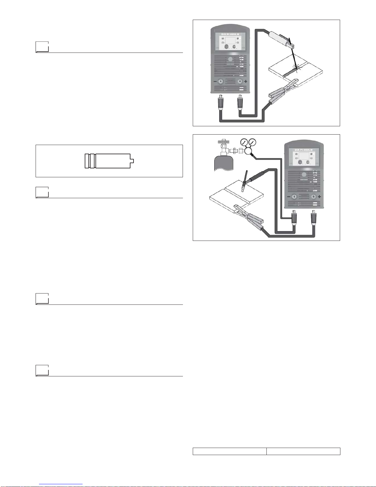
1) Connecting the welding cables (Fig. E):
•
Connect one end of the gas hose to the gas connecter on
the TIG torch and the other end to the pressure reducer
on the inert gas cylinder (Argon or similar).
• With the welding power source switched off:
-
Connect the ground cable to the snap-on connector
marked + (positive).
-
Connect the relative ground clamp to the workpiece or
to the workpiece support in an area free of rust, paint,
grease, etc..
-
Connect the TIG torch power cable to the snap-on con-
nector marked - (negative).
2) Switch the welding power source on by moving the power
supply switch to I(Pos. 3, Fig. A).
3) Make the adjustments and do the parameter settings on
the control panel.
4) Open the gas cylinder and regulate the flow by adjusting
the valve on the TIG torch by hand.
5) Ignite the electric arc by contact, using a decisive, quick
movement without dragging the tungsten electrode on the
piece to be welded (“Lift” type ignition).
6) The welder has a SWS “Smart Welding Stop” system for
the end of TIG welding. Lifting up the torch without switch-
ing off the arc will introduce a slope down and it will switch
off automatically.
7) When you have finished welding remember to shut the
valve on the gas cylinder.
Table 5 shows the currents to use with the respective elec-
trodes for TIG DC welding. This input is not absolute but is for
your guidance only; read the electrode manufacturers’instruc-
tions for a specific choice. The diameter of the electrode to use
is directly proportional to the current being used for welding.
Table 5
Ø ELECTRODE
(mm)
ELECTRODE TYPE
Current adjustment field (A)
TIG DC
Tungsten
Ce 1%
Grey
Tungsten
Rare ground 2%
Turchoise
110-50 10-50
1,6 50-80 50-80
2,4 80-150 80-150
3,2 150-250 150-250
4200-400 200-400
Maintenance
ATTENTION: Cut off the power supply to the equipment be-
fore effecting any internal inspection.
DIX PI 3006.M PULS, DIX PI 4006.M PULS and
DIX PI 4606.M PULS
IMPORTANT: For fully electronic welding power sources, re-
moving the dust by sucking it into the welding power source by
the fans, is of utmost importance.
In order to achieve correct functioning of the welding power
source, proceed as described:
•
Periodic removal of accumulations of dirt and dust inside the
equipment using compressed air. Do not point the jet of air
directly at the electrical parts as this could damage them.
•
Periodical inspection for worn cables or loose connections
that could cause overheating.
TORCH
The torch is subjected to high temperatures and is also stressed
by traction and torsion. We recommend not to twist the wire and
not to use the torch to pull the welder.As a result of the above
the torch will require frequent maintenance such as:
• Cleaning welding splashes from the gas diffuser so that the
gas flows freely.
• Substitution of the contact point when the hole is deformed.
•
Cleaning of the wire guide liner using trichloroethylene or
specific solvents.
• Check of the insulation and connections of the power cable;
the connections must be in good electrical and mechanical
condition.
SPARE PARTS
Original spares have been specifically designed for our equip-
ment. The use of spares that are not original may cause vari-
ations in the performance and reduce the safety level of the
equipment. We are not liable for damage due to use of spare
parts that are not original.
Optional
NOTE: The digital control unit of the welding power source is
fitted with a control recognition device which allows it to identify
which device is connected and take action accordingly.
REMOTE CONTROL ANALOGIC RC
This command (that must be plugged into the relevant connec-
tor on the front panel of the WF 793.M drawing unit):
•
Completely replaces the ENCODER - A knob on the WF
793.M feeder’s front panel.

9
•
Partially (depending on the welding process selected) re-
places the ENCODER - V knob on the WF 793.M feeder’s
front panel.
AIR AND/OR WATER COOLED UP/DOWN TORCH
This command (that must be plugged into the relevant connec-
tor on the front panel of the WF 793.M drawing unit) works as
an alternative to:
•
The ENCODER - A knob on the WF 793.M feeder’s front
panel. In “synergic” MIG MAG and “manual” MIG MAG weld-
ing processes, by pressing the two right (+) and left (-) but-
tons you can regulate the values for the synergic welding
parameters.
•
The ENCODER - V knob on the WF 793.M feeder’s front
panel. In the JOB welding process, by pressing the two right
(+) and left (-) buttons you can scroll the welding points set
previously.
The pointing out of any difficulties
and their elimination
The supply line is attributed with the cause of the most com-
mon difficulties. In the case of breakdown, proceed as follows:
1) Check the value of the supply voltage.
2) Check that the power cable is perfectly connected to the
plug and the supply switch.
3) Check that the power fuses are not burned out or loose.
4) Check whether the following are defective:
• The switch that supplies the welding power source
• The plug socket in the wall
• The welding power source switch
NOTE: Given the required technical skills necessary for the
repair of the welding power source, in case of breakdown we
advise you to contact skilled personnel or our technical ser-
vice department.
Replacing the digital interface PCB
Proceed as follows:
• Unscrew the 4 screws fastening the front rack panel.
• Remove both the adjustment knobs.
• Extract wiring connectors from the digital interface PCB.
• Unscrew the nuts and washers on the support.
•
Remove the digital interface PCB by lifting it out of its sup-
ports.
•
Proceed vice versa to assemble the new digital interface
PCB.

10
2101EA86
Wiring diagram

11
Key to the electrical diagram
•1•2•3•4•5
C2 CCI CHR Cp D2
•6•7•8•9•10
F-EMC IL L2 MIH MIL
•11 •12 •13 •14 •15
MV1-2 P1 P2 R2 RP
•16 •17 •18 •19
RS S-INT DIG S-INV S-LINK
•20 •21 •22 •23 •24
S-PS TA TH2 TP VR
•1 SNUBBER capacitor for output diodes •2 Interconnec-
tion cable connector •3 Cooling system power connector •4
Quick connection protection capacitor •5 Secondary diode
•6 EMC filter •7 Mains switch •8 Secondary inductor •9 Pri-
mary upper IGBT •10 Lower primary IGBT •11 Fan motor
•12 Main primary transformer (start) •13 Main primary trans-
former (end) •14 Output diode snubber resistor •15 Prima-
ry rectifier •16 Secondary rectifier •17 Digital interface PCB
•18 Inverter PCB •19 Capacitors PCB •20 Power Source
PCB •21 Hall effect transformer •22 Secondary thermostat
•23 Main transformer •24 Output diodes snubber varistor
Colour key
Ar Orange
Az Sky Blue
Bc White
Bl Blue
Gg Grey
Gl Yellow
GV Yellow-Green
Mr Brown
NA Black-Sky Blue
Nr Black
RN Red-Black
Ro Pink
Rs Red
Vd Green
Vl Violet

12
Meaning of graphic symbols on welding power source
Power supply switch
System for use in environments with in-
creased risk of electroshock
Product suitable for free circulation in the
European Community
Danger! high voltage
Grounding
Positive pole snap-in connector
Negative pole snap-in connector
Warning!
Before using the equipment you should
carefully read the instructions included in
this manual
Special disposal

13
Control panels
welding power source and wire feeder
Introduction....................................................................................15
General notes..................................................................................15
Welding machine control panel.....................................................................15
Wire feeder control panel .........................................................................15
WELDING MODE SELECTION Key ................................................................16
Switching on the welding machine .................................................................. 17
Language selection..............................................................................17
Screen saver................................................................................... 17
WELDING PROCESS SELECTION Menu (PROCESS) .................................................18
MIG-MAG, MIG pulse/dual pulse (DIXARC COOL PIPE, DIXARC COOL, DIX ARC HEAVY, DIXARC MEGA FAST
only if activated) ................................................................................19
1 - PROGRAM SELECTION Menu (PROGRAM) ......................................................19
2 - WELDING MODE SELECTION Menu (MODE) .....................................................19
3 - SPECIAL FUNCTIONS Menu (SET UP Fx) ........................................................20
4 - PRE-SETTING ..............................................................................24
5 - WELDING ..................................................................................25
6 - HOLD......................................................................................26
7 - WIRE LOADING .............................................................................27
8 - DOUBLE FEEDER ...........................................................................27
MMA .........................................................................................28
1 - PROGRAM SELECTION Menu (PROGRAM) MMA..................................................28
2 - SPECIAL FUNCTIONS Menu (SET UP Fx) MMA....................................................28
3 - PRE-SETTING MMA..........................................................................30
4 - WELDING MMA..............................................................................31
5 - HOLD MMA.................................................................................32
6 -ACTIVATING THE VRD DEVICE MMA............................................................33
TIG LIFT ......................................................................................34
1 - SPECIAL FUNCTIONS Menu (SET UP Fx) TIG LIFT.................................................34
2 - PRE-SETTING TIG LIFT.......................................................................35
3 - WELDING TIG LIFT...........................................................................36
4 - HOLD TIG LIFT ..............................................................................37
JOB/SEQUENCES..............................................................................38
1 - Creating and saving / editing and overwriting a JOB/SEQUENCES (*) JOB/SEQUENCES....................38
2 - JOB/SEQUENCES SELECTION Menu JOB/SEQUENCES............................................39
3 - PRE-SETTING JOB/SEQUENCES...............................................................40
4 - WELDING JOB/SEQUENCES ..................................................................41
5 - HOLD JOB/SEQUENCES......................................................................43

14
Error condition .................................................................................44
SETUP Menu ..................................................................................45
JOB EDIT SETUP Menu..........................................................................46
SEQ EDIT SETUP Menu .........................................................................46
PASSWORD SETUP Menu .......................................................................49
BLOCKS SETUP Menu ..........................................................................50
CONFIG SETUP Menu...........................................................................51
FACTORY RESET SETUP Menu...................................................................52
INFO SETUP Menu .............................................................................53
NETWORK SETUP Menu ........................................................................ 55
ERROR LOG SETUP Menu.......................................................................56
ADVANCED SETUP Menu........................................................................60
ADVANCED CONFIG ADVANCED SETUP Menu ......................................................61
ADVANCED MODE ADVANCED SETUP Menu........................................................62
WELDING MODE SELECTION Menu (MODE) ........................................................63
EQUIPMENT LAYOUTADVANCED SETUP Menu .....................................................64
WELD LOGADVANCED SETUP Menu..............................................................68

15
Introduction
This manual describes the functions of the software operating the following control panels:
• DIX PI 3006.M PULS + WF 793.M DIX PI 4006.M PULS + WF 793.M DIX PI 4606.M PULS + WF 793.M
Functioning of the panels listed above is identical (the functions are the same but the characteristics differ depending on the type
of machine they are fitted on (e.g.: current regulation field).
General notes
•
Any adjustments/changes made on the welder control panel are also displayed automatically on the drag-and-drop
control panel and vice versa, the images on the displays of both weld system components could however differ one
from the other, as the displays are consistent with adjustments/changes but also independent as far as visualization
is concerned.
•
The adjustments / changes made are immediately available to the operator, unless indicated otherwise in the manual.
Welding machine control panel
The panel on the generator has four keys, two encoders, and a colour display. The figure below shows the panel. The figure be-
low shows the image of the panel.
MENU KEy ENTER/MEM KEy
ENCODER KNOb - SX ENCODER KNOb - DX
DiSplay
SX KEy DX KEy
„PI 3006.M PULS“ / „PI 4006.M PULS“ / „PI 4606.M PULS“ CONTROL PANEL
Wire feeder control panel
The WF 793.M wire feeder panel has 2 keys, 2 encoders and 7 LEDs in the upper section and 4 keys and 5 LEDs in the lower
section. The figure below shows the panel. The figure below shows the image of the panel.
WElDiNG MODE SElECTiON lED
WElDiNG MODE SElECTiON KEy
WiRE KEy
ENCODER KNOb - a
paRaMETER SElECTiON KEy - a
paRaMETER SElECTiON lED - a
paRaMETER DiSplay SCREEN - a
SpECial FUNCTiONS (FX) lED
SpECial FUNCTiONS (FX) KEy
GaS KEy
ENCODER KNOb - V
paRaMETER SElECTiON KEy - V
paRaMETER SElECTiON lED - V
paRaMETER DiSplay SCREEN - V
HOLD Function LED
„WF 793.M“ CONTROL PANEL

16
WELDING MODE SELECTION Key
Each time this is pushed the following welding modes can be selected (only for pulsed and double pulsed MIG, synergic and
manual welding processes) on the feeder (on the welding machine the welding mode is selected using a specific menu - see the
appropriate paragraphs) according to a specific sequence:
SpOT lED
CRaTER lED
4T lED
2T lED
WElDiNG MODE SElECTiON lED
TWO STROKE (2T) 2T LED ( ) switched on
Pressing the TORCH TRIGGER starts the welding cycle, which will stop when it is released.
FOUR STROKE (4T) 4T LED ( ) switched on
1) Pressing and releasing the TORCH TRIGGER will start the welding cycle.
2) Pressing and releasing the TORCH TRIGGER will stop the welding cycle.
CRATER 2T 2T LED ( ) switched on - CRATER LED ( ) switched on
1) When the TORCH TRIGGER is pushed the arc ignites and the parameters assume the values for the “initial crater” for a time
set by means of the INITIAL CRATER DURATION (F10) function.
After that the parameter values become those for “welding” for a time defined by the INITIAL SLOPE (F11) function.
2) When the TORCH TRIGGER is released the parameters take on the “final crater” values for a time set by means of the FINAL
CRATER TIME (F15) function, for a period of time set using the FINAL SLOPE (F12) function.
CRATER 4T 4T LED ( ) switched on - CRATER LED ( ) switched on
1) When the TORCH TRIGGER is pushed the arc ignites and the parameters assume the values for the “initial crater”.
2) When the TORCH TRIGGER is released the parameters take on the “welding” values for a time set using the INITIAL SLOPE
(F11) function.
3) When the TORCH TRIGGER is pushed again the parameters take on the “final crater” values for a time defined using the
FINAL SLOPE (F12) function.
4) Releasing the TORCH TRIGGER will end the welding cycle.
SPOT WELDING 2T LED ( ) switched on - SPOT LED ( ) switched on
This is used so that on pressing the TORCH TRIGGER spot welding is done for a time period set beforehand (in seconds), after
which the arc switches off automatically.
STITCH WELDING 2T LED ( ) switched on - SPOT LED ( ) flashing
To begin stitch welding:
1) Press the TORCH TRIGGER to start the welding current and wire feed.
At this point the welding machine automatically carries out a succession of welded portions followed by a pause, according to
the times entered previously.
This procedure stops automatically only when the TORCH TRIGGER is released.
2) When the TORCH TRIGGER is pushed again the torch begins a new interval welding cycle.
CYCLE 4T LED ( ) switched on - CRATER LED ( ) flashing
■STANDARD
1) When the TORCH TRIGGER is pushed the arc ignites and the parameters assume the values for the “initial crater”.
2) When the TORCH TRIGGER is released the parameters take on the “welding” values for a time set using the INITIAL SLOPE
(F11) function.
3) When the TORCH TRIGGER is pushed and released within 1second, the parameters activated are those set for the “cycle”
functions. The operation can be repeated by switching between the “cycle” level and the “welding” level an infinite number of
times.
4) When the TORCH TRIGGER is pushed and held down for a period of time of more than 1 second, the parameters activated
are those with the values for the “final crater” for a period of time defined using the FINAL SLOPE (F12) function.
Releasing the TORCH TRIGGER will end the welding cycle.
■ADVANCED
InADVANCED operating mode, in addition to the settings described above, the welder is able to set the up “slope” (FIRST SLOPE
(F18)) and down “slope” (SECOND SLOPE (F21)) for the “cycle” level.

17
Switching on the welding machine
When the unit is switched on the welding machine's display shows a “sand glass”
During this operation, all keys and encoders of the welding power source panel are disabled.
Language selection
MENU KEy ENTER/MEM KEy
ENCODER KNOb - SX ENCODER KNOb - DX
DiSplay
SX KEy DX KEy
LANGUAGE ENGLISH
ADVANCE CONFIGURATION DISABLED
ADVANCE WELDING MODE DISABLED
COOLING MODE ON DEMAND
WIRE LOAD BY GUN DISABLED
WIRE LOAD SPEED 0.8 m/min
„PI 3006.M PULS“ / „PI 4006.M PULS“ / „PI 4606.M PULS“ CONTROL PANEL
On the display the DEFAULT language set by is ENGLISH.
To select another language, proceed as follows:
• Open the SETUP Menu by holding the
SX KEy
down for at least 5consecutive seconds.
• Select the CONFIG Menu by rotating the
ENCODER KNOb - SX
until the correct icon is reached.
• Push the
ENTER/MEM KEy
to open the CONFIG Menu.
• Select the LANGUAGE Sub-menu by rotating the
ENCODER KNOb - SX
.
• Select the language required by rotating the
ENCODER KNOb - DX
.
• Push the
MENU KEy
to close the CONFIG Menu.
• Push the
MENU KEy
to close the SETUP Menu.
Once this has closed, the display will show the various text / screens in the language selected.
Screen saver
After a pause or period of inactivity of the welding machine:
The display shows the SCREEN SAVER (moving ring).
• On both displays of the WF 793.M wire feeder, the middle line rolls continuously.
Display Display WF 793.M
The SCREEN SAVER mode can be exited in one of the following ways:
• By pushing any key or moving any knob on the welding machine's panel or that of the wire feeder.
• Starting the welding process, in which case the welding is activated in context.
• Moving a remote control.
When the SCREEN SAVER is exited, the welding machine goes back to the working condition prior to activation of the screen saver.

18
WELDING PROCESS SELECTION Menu (PROCESS)
„PI 3006.M PULS“ / „PI 4006.M PULS“ / „PI 4606.M PULS“ CONTROL PANEL
To access the PROCESS SELECTION Menu (PROCESS) push the
MENU KEy
.
MENU KEy ENTER/MEM KEy
ENCODER KNOb - SX
MIG PULSE
MIG DUAL PULSE
MIG/MAG SYNERGIC
MIG/MAG MANUAL
VISION.COLD
VISION.PIPE
VISION.POWER
1011 Fe G3 SI-1 Ø 0.8 Ar 16-20% CO2
MENU KEy ENTER/MEM KEy
ENCODER KNOb - SX
VISION.POWER
VISION.ULTRASPEED
MMA
TIG LIFT
TIG LIFT PULSE
JOB
SEQUENCES
1011 Fe G3 SI-1 Ø 0.8 Ar 16-20% CO2
MENU KEy
Provides access to the next menus.
ENCODER KNOb - SX
Select the welding process.
ENTER/MEM KEy
This key is used to access PRE-SETTING for the process selected.
(continued)
The following processes are available:
• MIG PULSE
• MIG DUAL PULSE
• MIG-MAG SYNERGIC
• MIG-MAG MANUAL
• DIXARC COOL (if activated)
• DIXARC COOL PIPE (if activated)
• DIXARC HEAVY (if activated)
• DIXARC MEGA FAST (if activated)
• MMA
• TIG LIFT
• TIG LIFT PULSE
• JOB (if JOBS have been created)
• SEQUENCES (if SEQUENCES have been created)
„WF 793.M“ CONTROL PANEL
It is not possible to access the PROCESS SELECTION Menu (PROCESS) via the WF 793.M control panel.

19
MIG-MAG, MIG pulse/dual pulse (DIX ARC COOL PIPE, DIX ARC COOL,
DIX ARC HEAVY, DIX ARC MEGA FAST only if activated)
1 - PROGRAM SELECTION Menu (PROGRAM)
„PI 3006.M PULS“ / „PI 4006.M PULS“ / „PI 4606.M PULS“ CONTROL PANEL
To access the PROGRAM SELECTION Menu (PROGRAM) push the
MENU KEy
.
MENU KEy ENTER/MEM KEy
ENCODER KNOb - SX
PRG MATERIAL Ø GAS
1011 Fe G3 SI-1 0.8 Ar 16-20% CO2
1012 Fe G3 SI-1 1.0 Ar 16-20% CO2
1013 Fe G3 SI-1 1.2 Ar 16-20% CO2
1014 Fe G3 SI-1 1.6 Ar 16-20% CO2
1021 Fe G3 SI-1 0.8 Ar 11-15% CO2
1011 Fe G3 SI-1 Ø 0.8 Ar 16-20% CO2
1/50
MENU KEy
Used to access subsequent menus if there are any.
ENCODER KNOb - SX
Select the welding program.
ENTER/MEM KEy
Used to access PRE-SETTING of the program selected.
(continued)
„WF 793.M“ CONTROL PANEL
It is not possible to access the PROGRAM SELECTION Menu (PROGRAM) via the WF 793.M control panel.
2 - WELDING MODE SELECTION Menu (MODE)
„PI 3006.M PULS“ / „PI 4006.M PULS“ / „PI 4606.M PULS“ CONTROL PANEL
To access the WELDING MODE SELECTION Menu (MODE) push the
MENU KEy
.
MENU KEy ENTER/MEM KEy
ENCODER KNOb - SX
TWO STROKE (2T)
FOUR STROKE (4T)
CRATER 2T
CRATER 4T
SPOT WELDING
STITCH WELDING
1011 Fe G3 SI-1 Ø 0.8 Ar 16-20% CO2
MENU KEy
Used to access subsequent menus if there are any.
ENCODER KNOb - SX
Select the welding mode.
ENTER/MEM KEy
Used to access the PRE-SETTING for the program selected beforehand, in the MODE
chosen.
(continued)
„WF 793.M“ CONTROL PANEL
To access the WELDING MODE SELECTION Menu (MODE) push the
WELDING MODE SELECTION KEy
.

20
WElDiNG MODE SElECTiON lED
WElDiNG MODE SElECTiON KEy
WELDING MODE SELECTION KEy
Scrolls the various welding modes available in succession.
WELDING MODE SELECTION LED Displays the welding mode selected.
(continued)
3 - SPECIAL FUNCTIONS Menu (SET UP Fx)
„PI 3006.M PULS“ / „PI 4006.M PULS“ / „PI 4606.M PULS“ CONTROL PANEL
To access the SPECIAL FUNCTIONS Menu (SET UP Fx) push the
MENU KEy
.
MENU KEy ENTER/MEM KEy
ENCODER KNOb - SX ENCODER KNOb - DX
DX KEy
1011 Fe G3 SI-1 Ø 0.8 Ar 16-20% CO2
DEFAULT
POST GAS 1.0 s
MENU KEy
Used to access subsequent menus if there are any.
ENCODER KNOb - SX
Used to select the various SPECIAL FUNCTIONS (Fx).
ENTER/MEM KEy
Used to access the PRE-SETTING for the program selected beforehand, in the MODE
chosen and with the changes made to the SPECIAL FUNCTIONS (Fx).
DX KEy
If held down for 2seconds it makes it possible to return the value for the SPECIAL
FUNCTION (Fx) selected to the DEFAULT value.
ENCODER KNOb - DX
Used to change the selected SPECIAL FUNCTION (Fx) value.
(continued)
This manual suits for next models
2
Table of contents
Other DINSEO Welding System manuals

DINSEO
DINSEO DIX GO 1306.M User manual

DINSEO
DINSEO DIX TIG GO 1806.M AC/DC User manual

DINSEO
DINSEO DIX TIG G O 1406.M HF Pro User manual

DINSEO
DINSEO DIX PI 270 User manual

DINSEO
DINSEO DIX GO 1106.M C User manual

DINSEO
DINSEO DIX TIG GO 1406.M HF User manual

DINSEO
DINSEO DIX GO 1206.M C User manual

DINSEO
DINSEO DIX TIG GO 1906.M HF User manual

DINSEO
DINSEO DIX GO 1206.M User manual