Will Burt AntennaMast AM2 with EZ RAZE User manual

Model AM2
with EZ RAZE®
Payload Elevation
System
Operator’s Manual
www.antennamast.com

Document History
Version Date Remarks
TP-5000901-00 04/03/14 Original Release
Will-Burt’s AntennaMast masts are portable, eld-erected masts. They are a fast and easy
solution for elevating a variety of payloads, including antennas, cameras and other sensors.
The AntennaMast is lightweight and can be manually transported and deployed by one
person.
This manual describes the installation, removal, and maintenance of Will-Burt’s
AntennaMast and accessories. The AntennaMast is available in 5 cm / 2 in. diameter and
maximum height of 15 meters. The AntennaMast will be referenced as the “mast” in the
remainder of this manual.
By adding accessories, the mast can be congured with 2, 3, or 4 arms in 6, 12, 24, 36 or
44 inch (15, 30, 60 cm or 1 meter) lengths. Optional payload adapters offered are:
• Bolster plate
• Cup holder
• NATO plate
• Blank plate
*Page 6 explains the installation of the mast and accessories.
**Page 7 lists the mast contents.
www.antennamast.com
Do not duplicate, alter, or copy without the written consent of e Will-Burt Company. © Copyright 2013 e Will-Burt Company
2
Introduction

Model #
Serial #
_____________
_____________
Safety Precautions
General Safety Precautions ...............................................4
Operating Safety Precautions ............................................5
Mast Deployment
Payload Capacity & Wind Effects ......................................6
Mast Contents ....................................................................7
Installating the Tripod ........................................ 9-10
Deploying the Mast ...............................................11
Deploying the EZ RAZE System ...................... 12-16
Installing the Accessories .....................................17
Guying the Mast .............................................. 18-19
Disassembling & Maintaining the Mast ..........................20
Customer Support
Warranty Information ........................................................21
Do not duplicate, alter, or copy without the written consent of e Will-Burt Company. © Copyright 2013 e Will-Burt Company 3
www.antennamast.com
Table of Contents

Safety Precautions
Per the ANSI Z535.4 standard, the following signal words and definitions are used to indicate
hazardous situations:
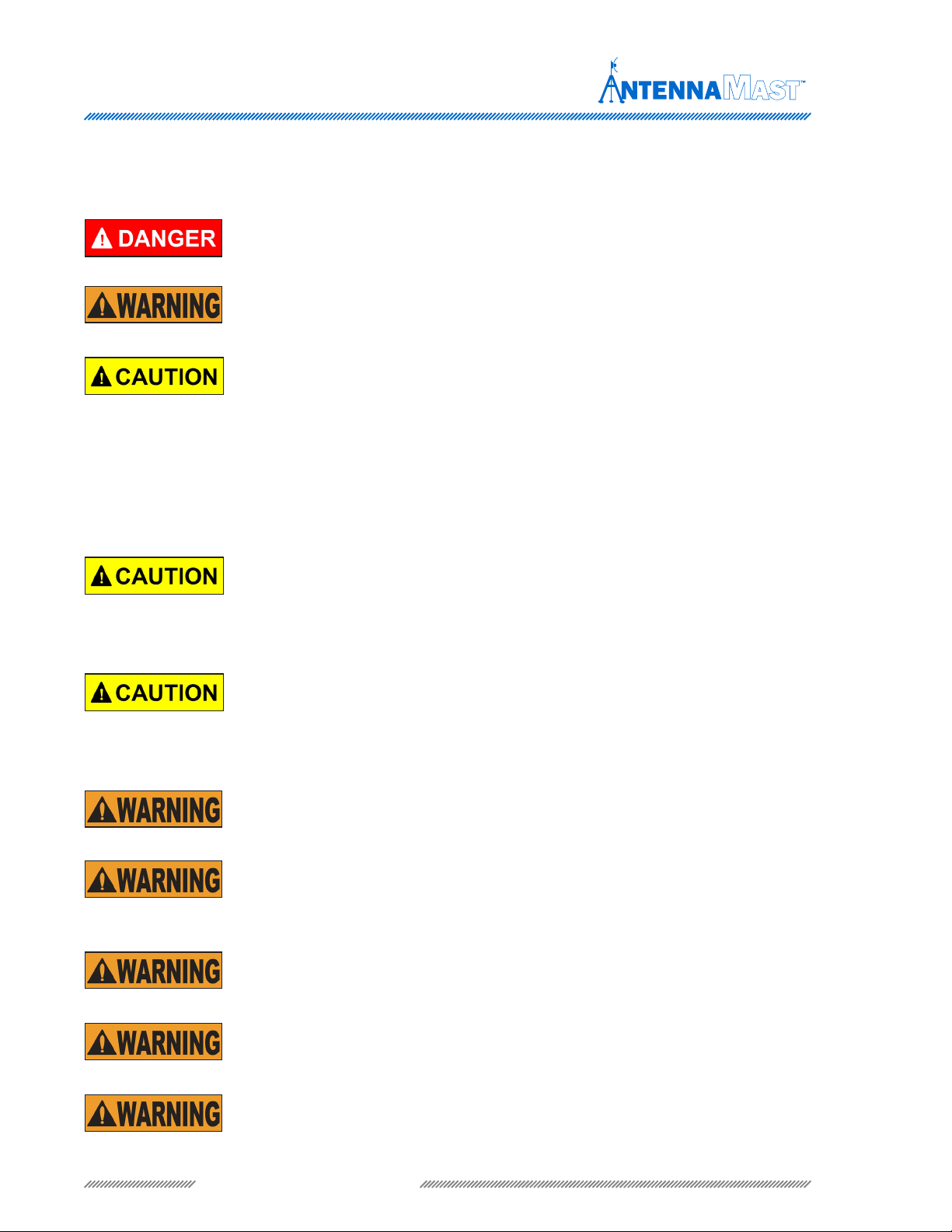
DANGER
indicates an imminently hazardous situation that, if not avoided,
will result in death or serious injury.
WARNING
indicates a potentially hazardous situation that, if not avoided,
could result in death or serious injury.
CAUTION indicates a potentially hazardous situation that, if not avoided,
may result in minor or moderate injury. It is also used to alert against
unsafe practices.
Lifting Hazard! In the UK, all lifting equipment must be thoroughly
examined annually by a trained person according to the Lifting Operations
and Lift Equipment Regulations 1998. Equivalent regulations exist in
other EU states.
Safety Instructions – Follow Procedure! Failure to follow drain kit
installation instructions could damage the mast and render the mast
inoperable. Read and understand the installation instructions before
installing the drain kit.
Do not deploy the mast if power lines are less than 80 ft. (24.4 m) from
the center of the deployment site.
Do not attempt to deploy the mast on soft or loose soil. The base plate
and guy stakes could become unstable under wind loading and cause the
mast to fall.
Do not attempt to deploy or retrieve this mast during electrical storms or
when winds exceed 20 mph.
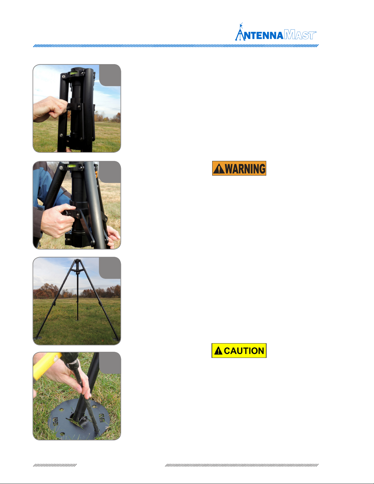
The mast must be vertical before deployment. Adjust guy lines as required
until the bubble level indicates the mast is vertical.
Helmets or hard hats, eye protection, gloves, and safety shoes or combat
boots must be worn while working in the mast deployment area.
Throughout this document safety precautions that are related to specific procedures appear
in this publication for emphasis. These are recommended precautions that personnel must
understand and apply during specific phases of installation, operation and maintenance.
www.antennamast.com
Do not duplicate, alter, or copy without the written consent of e Will-Burt Company. © Copyright 2013 e Will-Burt Company
4

Safety Precautions
Do not attempt to deploy the tripod on ground that slopes more than 5°.
Always observe weight lift limits.
Be mindful of buried cables when staking the mast.
Tip Over Hazard!
Mast tip over could result in death or serious injury. Do
not operate in high winds. Operate on level ground only. Stand clear of mast
and mast payload during operation. Be certain that the mast is level and
secure before and during installation, operation and maintenance.
Safety Instructions -
Trained Personnel Only! Death or serious injury
could result if proper inspection, installation, operation and maintenance
procedures are not observed. Installation, operation and maintenance
to be performed by trained and authorized personnel only. Proper eye
protection should be worn when servicing the mast.
Pinch Point Hazard!
Moving parts can crush and cut resulting in death or
serious injury. Keep clear of moving parts while operating mast.
Relocation Hazard! Relocating the mast during operation or after
extension could result in death or serious injury. Do not relocate the mast
during operation or while extended.
Lifting Hazard! The mast is intended to lift a specic payload for lighting,
surveillance or communication use only. Any other use without written
consent is prohibited and could cause death or serious injury. Do not
exceed specied payload capacity.
Electrocution Hazard! Contact with high voltage will result in death or
serious injury. Observe general safety precautions for handling equipment
using high voltage.
Do not locate or operate mast near electrical lines, cables
or other unwanted sources of electricity. Do not operate mast in lightning.
Be certain electrical cables are undamaged and properly terminated. Always
disconnect power before performing service, repair or test operations.
Do not duplicate, alter, or copy without the written consent of e Will-Burt Company. © Copyright 2013 e Will-Burt Company 5
www.antennamast.com

Payload Capacity & Wind Effects
www.antennamast.com
Do not duplicate, alter, or copy without the written consent of e Will-Burt Company. © Copyright 2013 e Will-Burt Company
6
The maximum payload for the mast is 22.6 kg / 50 lbs total. The payload weight should be evenly
distributed around or divided per arms on the mast. For example, if you have 4 arms and a total payload
of 22.6 kg / 50 lbs, place 5.65 kg / 12.5 lbs on each arm. The cable and platform bracket weight must
be considered in the maximum payload weight. If the cable weight is signicant, it may be possible to
route the cable opposite the payload weight or to loosely wrap the cable around the tubes.
Do not deploy the mast in winds greater than 32 kmh / 20 mph.
For payload weights and wind sail areas outside website specied
limits, contact the Will-Burt Company.
2m / 8 ft. to 15m / 49.2 ft. Deployment
Depending on the payload weight and the current wind speeds at
deployment, two or three people are required to raise a 2m / 8 ft. to 15m /
49.2 ft. mast. One person is typically required to load the mast tubes while
one or two people manage the guy lines. Typically, single staking the tripod base
plates is sufcient. Contingent upon the payload weight and the current wind
speeds at deployment, three to ve people are required to raise a 13m / 42.6 ft.
to 15m / 49.2 ft. tall mast. One or two people are required to load the mast tubes
while two or three people manage the guy lines. Double staking the tripod base
plates is required.
To install the mast and accessories, you will perform the following major tasks:
1. Select a Level and Safe Site
2. Begin Mast Installation
• Unpack
3. Set Up the Tripod
• Level the Tripod
• Stake the Tripod
4. Install the Top of the Mast
• Insert the Top Tube
• Install Accessory Arm Collar and Guy Collar (for Accessories only)
• Install the 4-way Guy Collar
• Connect to Guy Collar
• Fully Raise the Tripod Legs
5. Raise the Mast
• Stage & Stake guy lines
• Load Tubes
• Install Base Tube
• Stake the Base Plate
• Tighten the guy lines

The following items are required for deployment of Will-Burt’s AntennaMast.
Mast Contents
Accessory Bag Description
Wheeled Bag
Guy Accessory Kit
EZ RAZE Payload Elevation Kit
Mast Tube Lift Winch Kit (some models)
Payload Accessory Kit (as ordered)
1m Mast Tubes
Base Tube
Tripod
Operator’s Manual
Quick Reference Sheet
Guy Accessory Kit
Ground Stakes
Guy lines
Hammer
Stake Puller
Manual Lifter (supplied in place of Mast Tube Lift Winch)
EZ RAZE Payload
Elevation Kit
EZ RAZE Carriage
EZ RAZE Top Tube
EZ RAZE Winch
Mast Tube Lift Winch Kit
Orange Lift Plate
(Some models)
Orange Winch w/Key
Payload Accessory Kit
As ordered
Do not duplicate, alter, or copy without the written consent of e Will-Burt Company. © Copyright 2013 e Will-Burt Company 7
www.antennamast.com

Manual Deployment
www.antennamast.com

1
22
33
44
1. To Ensure Safe Installation: Select a level site to deploy the
system that has no more than a 5° slope. Beware of surroundings and
ensure that the center of the site is approximately 2.1m / 7 sq. ft. The
center of the site is where the tripod will be located in the installation.
Ensure that the site has adequate overhead and ground clearances.
The overhead clearance must be at least the height of the mast. The
ground clearance must be a radius equal to the height of the mast.
For example, for a 4m / 13.1 ft. mast, ensure that the site has an
overhead clearance of 4m / 13.1 ft. and a clear radius of 4m / 13.1
ft. from the center of the site.
2. Unzip the wheeled bag, remove the tripod, guy bag and
accessory bag.
3. With all three base plates of the tripod on the ground,
loosen each leg clamp by turning the knob to the left.
4. Step on the base plates and lift the tripod up until the
legs are fully extended. Lock each clamp by turning the
knob to the right until tight.
Installing the Tripod
Do not duplicate, alter, or copy without the written consent of e Will-Burt Company. © Copyright 2013 e Will-Burt Company 9
www.antennamast.com

Installing the Tripod
5
8
6
7
5. Pull on the key ring then pull on the tripod leg to deploy
the tripod. This unlocks the tripod.
6. Open the tripod by pushing down on the central collar
until the pin snaps into the next groove and the base
plates are at on the ground. Keep fingers away from the
pinch points.
7. Make sure the tripod is fully deployed before adding
the next tube and payload(s). Check the front level. If the
tripod is not level, loosen one of the adjacent leg clamps
and adjust leg length to level the tripod. Tighten the leg
clamp. Check the side level. If the tripod is not level,
loosen one of the adjacent leg clamps and adjust the
length. Tighten the leg clamp. Make sure all leg clamps
on the tripod are tight.
8. Stake the Tripod: Remove the stakes and hammer from
the guy bag. For masts 2m / 6.5 ft. to 12m / 39.3 ft. tall
and smaller payloads, one stake per tripod leg plate may be
sufcient. For masts taller than 12m / 39.3 ft., two stakes are
required on each tripod leg plate. Stake the base plates of
each leg by driving a stake(s) in the two stake holes aligned
with the pivot point of the base blate using the hammer.
Stakes
should be driven at an angle with the eyelet toward the tripod leg.
Be careful of buried cables and utilities when staking the mast.
www.antennamast.com
Do not duplicate, alter, or copy without the written consent of e Will-Burt Company. © Copyright 2013 e Will-Burt Company
10

2
3
1
EZ RAZE Top Tube
Tube Sections Base Tube
Deploying the Mast
1. Locate the base tube and keep separate from the other
mast tubes. The AM2 has three different tubes:
2. Retrieve the EZ RAZE top tube and tube section and
insert the tube section from the bottom of the tripod with
the locating notches toward the ground. Take note of
small dimple in one of the locating notches on the bottom
of the mast tube. Orient this dimple toward you during
deployment of the mast.
3. Lift the tube until there is one hand width from the
bottom of the tube and tighten the clamp.
4. To install the EZ RAZE system, open up the restrain
system by engaging the kick stand lever to the lower bar.
Then, slide the EZ RAZE carriage over the top of the tube
section until resting on the top of the tripod.
4
Do not duplicate, alter, or copy without the written consent of e Will-Burt Company. © Copyright 2013 e Will-Burt Company 11
www.antennamast.com

EZ RAZE Deployment
5. Slide EZ RAZE top tube down through carriage and rotate
it until locating notches fully engage with the tube making
sure to align dimples for proper orientation. Make sure
the restrain mechanism is the opposite direction as the
operator.
6. Before deploying the mast tube sections, attach guy
lines to the top guy collar. Preferred method of attaching
the hook is to hook up through the guy plate on the EZ
RAZE top tube as shown.
7. Align the guy stakes to coincide with the four holes on
the guy collar on the top of the mast (not required to align
for the swivel collar since it automatically adjusts to the
stakes) and place 90° apart. See guy line instructions.
1. To install the lift winch, insert the round key of the blue
winch into the tripod receiver below the blue hold down
clamp.
5
6
7
8
www.antennamast.com
Do not duplicate, alter, or copy without the written consent of e Will-Burt Company. © Copyright 2013 e Will-Burt Company
12
Hold Down ClampTripod Receiver

EZ RAZE Deployment
2. With the winch in place, rotate the carriage so the
corner with 2 eyelets are aligned above the blue winch.
Also, make sure the pulley in the top of the EZ RAZE tip is
in line with the winch. Take the end of the cable and feed
it up through the 2 eyelets on the EZ RAZE carriage.
9
10
11
12
3. Winch cable routing is always between the spool and
standoffs. Never route the cable over standoffs to the next
contact point.
4. Take the end of the cable and feed it up through the 2
eyelets on the EZ RAZE carriage.
5. Then feed the cable through the top pulley of the tip
and back down the other side of the carriage. Make sure
the cable passes back down through the backside (180°)
to single eyelet.
Do not duplicate, alter, or copy without the written consent of e Will-Burt Company. © Copyright 2013 e Will-Burt Company 13
www.antennamast.com

13
14
15
6. Attach the end of the cable to the carriage safety
restraint. To do this, feed the ball end of the cable through
the top hole in the black receiver plate from the side with
the slot cutout at the top.
7. Hold the ball end of the cable down and take up the
slack in the cable from the top, seating the ball into the
recess in the bottom of the black receiver plate.
8. Then take the end of the cable and feed it through the
bottom hole in the black receiver plate from the side with
the slot cutout between the two holes.
EZ RAZE Deployment
16
9. Correct installation of cable end to the receiver plate.
www.antennamast.com
Do not duplicate, alter, or copy without the written consent of e Will-Burt Company. © Copyright 2013 e Will-Burt Company
14

10. Reset the restrain lever to open if accidentally tripped
when raising the mast.
11. Leave cable loose while deploying the mast by
unwinding several feet of cable from the winch with every
tube section deployed.
17
19
12. Manually load tube sections into the bottom of the
installed top tube, matching the notches on the top tube
with the notches on the top of the next tube in the tripod.
Match dimple proles if payload alignment is required.
EZ RAZE Deployment
19
18
20
13. While holding onto the tube that was just loaded,
loosen the lower clamp to the left. Push the tube up until
only a hand’s length is visible, then tighten the clamp to
the right. The manual lifter can also be used to push the
tubes up. Repeat this step until all tubes are loaded.
Tighten tripod clamp to maintain azimuth direction.
Do not duplicate, alter, or copy without the written consent of e Will-Burt Company. © Copyright 2013 e Will-Burt Company 15
www.antennamast.com

EZ RAZE Deployment
14. Place the base tube (tube with the base plate
attached) into the bottom tube matching the locating
notches and aligning the dimples. Raise the base tube
until the locating notches are fully engaged. While holding
onto the base tube, loosen the clamp and slowly allow
mast tubes to be lower to rest on the ground. Tighten
clamp.
15. Stake the base plate of the base tube by driving the
stake, with the hammer provided, at a point aligned with
pivot point of the base plate.
16. Stake the base plate of the tube by driving the stake
through holes with the hammer provided. For masts 2m /
8 ft. to 12m / 40 ft. tall and smaller payloads, one stake
may be sufcient. For masts taller than 12m / 40 ft., two
stakes are required, depending on the soil type.
21
22
23
www.antennamast.com
Do not duplicate, alter, or copy without the written consent of e Will-Burt Company. © Copyright 2013 e Will-Burt Company
16

Installing the Accessories
2
3
1. Attach payload platform to the carriage by inserting
the ¼” quick release pins through carriage and platform.
Shown is an extension arm carriage attachment.
2. Pick a preferred angle for the arm, line up the arm
hole with the arm collar hole, and pin the arm in place by
pressing the button.
1
3. Match a corresponding angle for the payload adaptor,
line up the arm hole with adapter hole, and pin the arm in
place by pressing the pin button.
Do not duplicate, alter, or copy without the written consent of e Will-Burt Company. © Copyright 2013 e Will-Burt Company 17
www.antennamast.com

Guying the Mast
3
4
2
1
1. Set-Up the guy lines: Align the guy stakes from the
mast at 90° apart (not required to align for the swivel collar
since it automatically adjusts to the stakes).
2. Drive each stake, with the hammer provided, into the
ground at a 45° angle away from the tripod. Ensure that
the stake is driven into the ground up to the eyelet of the
stake and that the eyelet is pointing towards the tripod.
If possible, drive the stakes a distance equal to the
mast height from the center of the mast. Consult The
Will-Burt Company for modified distance.
3. Clip the carabineer to the swiveling guy collar which is
done before raising the mast.
4. Clip the carabineer of each of the tensioners to the ring
of the guy stake.
www.antennamast.com
Do not duplicate, alter, or copy without the written consent of e Will-Burt Company. © Copyright 2013 e Will-Burt Company
18

Guying the Mast
46
5
7
5. Stage the guy lines: For masts near maximum payloads
and for masts 13m / 44 ft. to 18m / 60 ft. tall, prepare
the guy lines by loosening a maximum of 1.5m / 5 ft. of
guy line from each tensioner.
6. Tighten the guy lines: Tension the lines by sliding the
tension toward the mast. Do not over tighten the guy lines.
Tighten the lines to the point that the mast is stabilized,
sway is minimized, and the mast is stable during winds.
Over tightening the guy lines causes an additional or
unlevel load on the mast and reduces the overall load
capacity of the mast. Ensure that the guy lines are not
crossed, and that the guy line attached to the stake
coincides with the aligned hole in the guy collar on top
of the mast.
7. Lock the tensioner into position by sliding the tensioner
toward the mast and placing the tensioner hook over the
double guy line. Check to make sure the center mast
tube remains straight and perpendicular. Check guy
lines to ensure no interfering with raising payload has
occured. To adjust the guy line, move the ground stake
related to the guy line by a couple of degrees.
Do not duplicate, alter, or copy without the written consent of e Will-Burt Company. © Copyright 2013 e Will-Burt Company 19
www.antennamast.com

Disassembling the Mast
To disassemble the mast, proceed as follows:
1. Lower payload back down to tripod level. It is optional to dismantle the payload at this time.
2. Loosen the cable and guy lines to relieve tension on the mast and to pick up the mast to remove the
base tube.
3. While holding the exposed portion of the tube (held by the mast clamp), loosen the mast clamp and
ease the tube down to where the tube is free from the clamp. Allow the next tube to slowly lower until it
enters the clamp and a hands width of tube is exposed. Tighten the clamp and remove the free tube from
under the tripod. If using winch, rotate handle counter clockwise to lower. Crank the cable onto the winch
while lowering the mast sections.
4. If accessories are installed on the tube, disassemble the accessories and place in the bags.
5. Repeat steps 3 and 4 for the remaining tubes until all the tubes have been removed (except for the top
tube). Place the tubes in the tube bag.
6. Remove the ground stakes from the tripod base plate and place them in the guy bag.
7. Loosen the clamps on the tripod legs and allow the legs to retract within themselves, bringing the mast
to a comfortable working height. (Optional)
8. Detach the guy line hooks from the guy collar on the top tube.
9. Detach the guy line hooks from the stakes. Wind the guy line around the tensioner. Remove the
stakes. Place the guy lines and stakes in the guy bag.
10. Remove the 4-way guy collar or the accessory guy collar from the top tube and place the guy collar
and top tube in a bag.
11. Pull the spring loaded pin on the tripod and fold up the tripod for transport.
12. Place the tripod and base plates in a bag.
To maintain the mast and accessories, perform the following checks on a regular basis:
1. Inspect nuts and bolts.
2. Inspect all clamps for cracks or uneven wear.
3. Inspect the tripod for uneven wear.
4. Inspect all guy lines for frayed or cut lines.
5. Inspect guy handles for cracks or tears.
6. Wipe down all parts with a cloth
Maintaining the Mast
www.antennamast.com
Do not duplicate, alter, or copy without the written consent of e Will-Burt Company. © Copyright 2013 e Will-Burt Company
20
Table of contents
Other Will Burt Antenna manuals