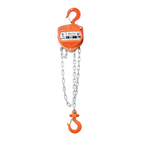
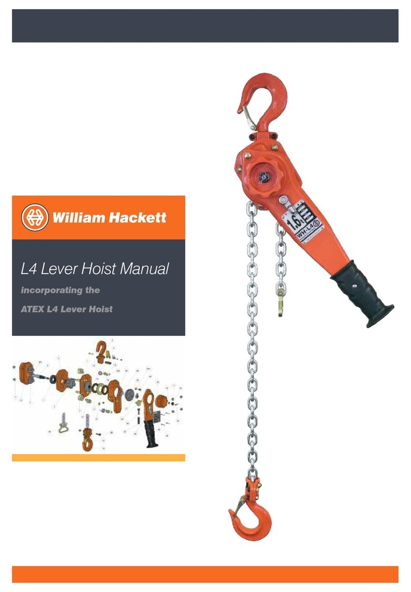
William Hackett L5 QP User manual

1
L5 QP
Lever Hoist
User Manual
WHM-0021


3
Contents
1. Dimensions and Specifications ................................................................................................. 4
2. Hoist Selection ........................................................................................................................... 5
3. Pre-use checks........................................................................................................................... 6
4. Hoist Operation ......................................................................................................................... 7
5. Safe Use Information ................................................................................................................. 8
6. Spare Parts Inspection Category ............................................................................................... 9
7. Parts List .................................................................................................................................... 10
8. Parts Explosion ........................................................................................................................... 11
9. Hoist Disassembly ..................................................................................................................... 12
10. Maintenance and Repair ............................................................................................................ 13-23
11. Assembly Instructions ................................................................................................................ 24
12. Brake Set-up .............................................................................................................................. 25-29
13. Miscellaneous ............................................................................................................................ 30
14. Warranty ..................................................................................................................................... 35
APPENDIX
Fleeting Guidance 34-41

4
Dimensions and Specifications
Table 1: Product specification, dimensions and WLL for William Hackett L5 QP lever hoists
Part
Code
WLL
tonnes
No. of
Falls
Load
Chain
mm
a
mm
b
mm
c
mm
d
mm
e
mm
h min
mm
Mass
kg
1.5M
HOL
Extra
Weight
per M
kg
035.080 0.8 1 5.6 x 15.7 146 119 42.0 245 27 280 5.9 0.70
035.160 1.6 1 7.1 x 19.9 164 126 54.5 265 36 335 7.4 1.12
035.320 3.2 1 10 x 28 196 159 60.5 415 42 395 13.7 2.23
035.630 6.3 2 10 x 28 196 218 85.5 415 52.5 540 26.4 4.46
035.1000 10.0 3 10 x 28 196 298 86.0 415 59 680 40.1 6.69
035.1500 15.0 6 10 x 28 196 420 -415 80 1000 70.2 13.38

5
Hoist Selection
In accordance with statutory requirements (e.g. The Lifting Operations and Lifting Equipment Regulations
1998), all lifts using lever hoists should be planned by a competent person; require risk assessment and the
production of a task method statement; and be subject to execution by suitably trained operatives under
the supervision of a responsible person. The specification of the lever hoist required to achieve a safe lifting
operation must be determined by a competent person.
It is not intended that the recommendations in this manual take precedence over existing plant safety rules and
regulations or OSHA regulations. In the event that conflict exists between a rule set forth in this publication and
a similar rule already set by an individual company, the more stringent of the two should take precedence.
Careful consideration should be given to the mass of the load being lifted and any dynamic factors that may
be likely to affect the load on the hoist. Select the hoist capacity equal to or greater than the load. Ideally lever
hoists should not be used to lift loads below 10% of their rated WLL limit.
William Hackett L5 QP lever hoists are assembled, chained and tested in the UK to the height of lift specified by
the end user. Careful consideration should be given to the headroom required to lift the load and the position of
the operator before specifying the length of load chain and the hoist model.
The configuration of lever hoist assemblies are demonstrated on page 4, and are in accordance with the
product specification, dimensions and working load limit (WLL) recorded in Table 1 (also on page 4).
William Hackett L5 QP lever hoists are designed for the most demanding industrial applications.
William Hackett L5 QP lever hoists can be used within an operating temperature range of -20°C to +120°C.
William Hackett L5 QP hoists are suitable for fleeting lifting. If multiple hoists are to be used in a fleeting
operation, refer to Appendix 1: General Guidance for Fleeting Lifting at the end of this manual.
A thorough study of the information in this manual should provide a better understanding of safe operating
procedures and afford a greater margin of safety for people and equipment.

6
Pre-use checks
Before the lever hoist is issued from the designated storage location a competent person must ensure that the
appropriate certification is in place for the hoist.
Safe use instructions should be made available.
Possession of the relevant certification does not absolve the user from his responsibility to carry out pre-use
inspections.
Conducting thorough and consistent checks on a lever hoist immediately prior to use will help identify problems
due to accidental damage, internal corrosion, brake contamination or inappropriate storage.
Points to check before each period of use are:
• If necessary, the hoist should be cleaned before inspection.
• Name Plate – details clear and visible
• Hook latches in good working order
• Is the Load chain worn or damaged. In particular attention should be given to the wear which occurs on
the bearing surfaces inside the links and to damage in the form of bent, notched, stretched, or excessively
corroded links and the chain should move freely.
• Obvious signs of hooks opening out increase in throat opening or any other form of distortion in the hooks
or suspension fittings.
• Top and bottom hooks free to rotate with no load applied.
• With no load applied turning the grip ring clockwise should produce a clear and positive clicking sound as
the brake ratchet activates.
• On multiple fall hoists check that all chain sheaves are free to rotate whilst no load is applied.
• Check all fixings are in place and in good condition, split pins or nyloc nuts.
• Obvious signs of damage to the hoist slack end chain anchor.
• General damage to the hoist body, this can be an indicator of neglect throughout the hoist.
• The load chain wheel should be checked for damage or debris
• Chain guides and strippers should be free of debris and in good condition.
These checks should be performed with the hoist unloaded.
• Lifting function - select ‘UP’ and whilst pulling the load side of the chain, operate the lever handle clockwise,
the ratchet brake mechanism shall engage operate smoothly without snagging.
• Lowering function - Select ‘DN’ and with a light pull of the load side chain, operate the lever counter
clockwise, no clicking shall be audible and the chain should pay out smoothly.
• Neutral or free chaining - with the selector lever in the ‘N’ position. Pull the grip ring out. The chain shall then
adjust freely via the grip ring or by pulling of the load chain.
If any of these points are not satisfied the hoist MUST NOT be used.

7
Load Chain Dual Anti-Lock Brake System (DABS)
operation
The Hackett SS-L5 QP lever hoist may be used either
in the vertical position as a hoist; or in an angled or
horizontal position as a puller. Below is the general
procedure for operating the hoist:
1. Locate the top hook securely.
2. To engage the chain adjustment mechanism
position the selector lever in the neutral position (N).
3. Pull the grip ring out as shown in figure 2, the
unloaded load chain can now be adjusted to the
required position.
4. To re-engage hold the load chain to prevent chain
travel and push the grip ring in with a clockwise
motion as shown in figure 3.
5. To raise the load:
Move the selector lever to the up position
and rotate the lever handle clockwise.
6. To lower the load:
Move the selector lever to the down position
and rotate the lever handle counter clockwise.
Hoist Operation
Serial No:
HOL:
Date:
Chain:
3.2
t
• William Hackett • UK
SS-L5
QUAD PAWL
LEVER HOIST
Up Down
Neutral
WLL
→
→
N
Serial No:
HOL:
Date:
Chain:
3.2
t
• William Hackett • UK
SS-L5
QUAD PAWL
LEVER HOIST
Up
Down
Neutral
WLL
→
→
N
Serial No:
HOL:
Date:
Chain:
3.2
t
• William Hackett • UK
SS-L5
QUAD PAWL
LEVER HOIST
Up
Down
Neutral
WLL
→
→
N
Figure 2
Figure 3

8
Safe Use information
Do not attempt lifting operations unless you understand the use of the equipment, the lifting and slinging
procedures and you have been suitably trained.
William Hackett L5 QP lever hoists are not designed for lifting people and should not be used for that purpose.
Use appropriate personal protective equipment (PPE).
Check the correct engagement of the top and bottom hooks.The hooks should be free to articulate within the
load attachment points without overcrowding.
Do not use the handwheel whilst the hoist is loaded.
When the hoist is under load ensure that the selector lever is in the UP position.
Whilst loaded do not try to make chain adjustments by pulling the load chain.
Ensure that the work area is clear to avoid the slack end chain snagging in use.
Ensure that the suspension structure has sufficient load bearing strength and capacity to support the load.
Do not use the lever hoist as a chain sling; it is a lifting appliance and suitable lifting accessories should
be incorporated into the lift plan to facilitate a safe lifting operation.
If more than one lever hoist is to be used, refer to Appendix 1: General Guidance for Fleeting Lifting at the end
of this manual.
Establish a clearly defined zone around the area of the lifting operation.
Always stand aside from the load when operating the hoist and ensure that no one enters the lift zone
unintentionally during the lifting operation.
Ensure that the load chain is not twisted, particular care should be taken when using multi-fall
hoists.
During the lift the load chain should be straight and should not contact any angles or edges.
Take the load steadily and avoid shock loads.
Do not expose lever hoist assemblies, chain slings and components to chemicals or corrosive solutions
(whether immersed in such solutions or used in atmospheres in which fumes are present), particularly acidic or
strongly alkaline environments without consulting the supplier or manufacturer.
Do not leave suspended loads unattended. In an emergency cordon off the working area and establish safe
exclusion zones.
Never return a damaged lever hoist to stores; it should be reported to a competent person.

9
Spare Parts Inspection Category Spare Parts Inspection Category
SPECIAL INSPECTION - Type 1
Corrosion Protected / Stainless Steel
/ Copper Components
(Do Not Shotblast)
STANDARD INSPECTION - Type 2 Standard Corrosion Protected
or Painted Components
Part
Code Quantity Description Inspection Type (1 or 2)
L5 QP
L5.QP.01 1 Gear Cover 2
L5.QP.02 2 Pinion Gear (pair) 2
L5.QP.03 1 Pinion Shaft 2
L5.QP.04 1 Load Gear 2
L5.QP.05 1 Gear Side Plate Assembly 2
L5.QP.06 1 Bearing 2
L5.QP.07 1 Load Sheave 2
L5.QP.08 2 Chain Guide 2
L5.QP.09 1 Chain Stripper 2
L5.QP.10 1 Lever Side Plate Assembly 2
L5.QP.11 2 Stainless Steel Pawl Spring 2
L5.QP.12A 1 Upper Pawl 2
L5.QP.12B 1 Lower Pawl 2
L5.QP.13 2 Circlip 2
L5.QP.14 1 Disc Hub 2
L5.QP.15 1 Ratchet Gear 2
L5.QP.16 1 Brake Cover Assembly 2
L5.QP.17 2 Lever Side Plate Nyloc Nut (M6) 2
L5.QP.19 8 Lever Hoist Cover Nyloc Nut (M8) 2
L5.QP.20 1 Change Gear 2
L5.QP.20L 1 Load Limiter 2
L5.QP.21 1 Change Over Pawl 2
L5.QP.22 1 Change Over Stand 2
L5.QP.23 1 Change Over Spring 2
L5.QP.24 1 Handle Assembly 2
L5.QP.25 1 Screw 2
L5.QP.25A 1 Spring Washer 2
L5.QP.26 1 Cam 2
L5.QP.27 1 Twisting Spring 1 2
L5.QP.28 1 Grip Ring 2
L5.QP.29 1 Twisting Spring 2 2
L5.QP.30 1 Spring Housing 2
L5.QP.31 1 Castle Nut 2
L5.QP.32 1 Split Pin 2
L5.QP.35 1 Chain End Fixing Pin Nyloc Nut 2
L5.QP.36 1 Bottom Hook Chain End Fixing Pin 2
L5.QP.37 2 Latch Kit 2
L5.QP.38 1 Bottom Hook Assembly 2
L5.QP.39 1 Top Hook Pin 2
L5.QP.40 1 Top Hook Assembly 2
L5.QP.41 1 Handle End Stop 2
L5.QP.42 1 Pinion Shaft Washer 2
L5.QP.47 1 Top Hook Chain Fixing Pin 6.3t and 10t 2
L5.QP.49 Per Metre Calibrated Load Chain 2
L5.QP.50 1 Rubber Handle Nut 2
L5.QP.50A 1 Rubber Handle Bolt 2
L5.QP.62 1 Rubber Handle with Enlarged Pommel 2
L5.QP.63 1 Label 2
L5.QP.64 4 Label Rivets 2

10
Parts List
Part Code Part Name Quantity Finish Included in
Service Kit
L5.QP.01 Gear Cover 1 Powder Coated No
L5.QP.02 Pinion Gear (pair) 2 Self Colour No
L5.QP.03 Pinion Shaft 1 Zinc Chromate Yes
L5.QP.04 Load Gear 1 Self Colour No
L5.QP.05 Gear Side Plate Assembly 1 Powder Coated No
L5.QP.06 Bearing 1 Steel Yes
L5.QP.07 Load Sheave 1 Zinc Chromate No
L5.QP.08 Chain Guide 2 Zinc Chromate No
L5.QP.09 Chain Stripper 1 Zinc Chromate No
L5.QP.10 Lever Side Plate Assembly 1 Powder Coated and Zinc Chromate Yes
L5.QP.11 Stainless Steel Pawl Spring 2 Stainless Steel Yes
L5.QP.12A Upper Pawl 1 Zinc Chromate Yes
L5.QP.12B Lower Pawl 1 Zinc Chromate Yes
L5.QP.13 Circlip 2 Stainless Steel Yes
L5.QP.14 Disc Hub 1 Zinc Chromate Yes
L5.QP.15 Ratchet Gear 1 Zinc Chromate Yes
L5.QP.16 Brake Cover Assembly 1 Powder Coated No
L5.QP.17 Lever Side Plate Nyloc Nut (M6) 2 Stainless Steel Yes
L5.QP.19 Lever Hoist Cover Nyloc Nut (M8) 8 Stainless Steel Yes
L5.QP.20 Change Gear 1 Zinc Chromate Yes
L5.QP.20L Load Limiter 1 Zinc Chromate / Mixed No
L5.QP.21 Change Over Pawl 1 Zinc Chromate No
L5.QP.22 Change Over Stand 1 Zinc Chromate No
L5.QP.23 Change Over Spring 1 Zinc Chromate No
L5.QP.24 Handle Assembly 1 Powder Coated No
L5.QP.25 Screw 1 Stainless Steel No
L5.QP.25A Spring Washer 1 Stainless Steel No
L5.QP.26 Cam 1 Zinc Chromate Yes
L5.QP.27 Twisting Spring 1 1 Stainless Steel Yes
L5.QP.28 Grip Ring 1 Powder Coated No
L5.QP.29 Twisting Spring 2 1 Stainless Steel Yes
L5.QP.30 Spring Housing 1 Powder Coated No
L5.QP.31 Castle Nut 1 Stainless Steel No
L5.QP.32 Split Pin 1 Stainless Steel No
L5.QP.35 Chain End Fixing Pin Nyloc Nut 1 Zinc Chromate and Stainless Steel No
L5.QP.36 Bottom Hook Chain End Fixing Pin 1 Zinc Chromate and Stainless Steel No
L5.QP.37 Latch Kit 2 Zinc Chromate and Stainless Steel No
L5.QP.38 Bottom Hook Assembly 1 Powder Coated and Stainless Steel No
L5.QP.39 Top Hook Pin 1 Zinc Chromate No
L5.QP.40 Top Hook Assembly 1 Powder Coated and Stainless Steel No
L5.QP.41 Handle End Stop 1
L5.QP.42 Pinion Shaft Washer 1 Black No
L5.QP.47 Top Hook Chain Fixing Pin 6.3t and 10t 1 Zinc Chromate No
L5.QP.49 Calibrated Load Chain Per Metre Zinc /Galvanised No
L5.QP.50 Rubber Handle Nut 1 No
L5.QP.50A Rubber Handle Bolt 1 No
L5.QP.62 Rubber Handle with Enlarged Pommel 1 Rubber No
L5.QP.63 Label 1 Stainless Steel No
L5.QP.64 Label Rivets 4 Stainless Steel No
No

Parts Explosion

12
Hoist Disassembly
The following procedures should only be performed by a competent person.
It is a responsibility of the owner/user to install, operate, inspect and maintain product in accordance with
all applicable Standards and Regulations. If the product is installed as part of a lifting system, it is also the
responsibility of the owner/user to comply with the applicable standards that address other types of equipment
used.
NEVER perform maintenance whilst the hoist is under load. Always use OEM parts where replacement parts are
necessary.
These instructions should be used alongside the illustrated parts list.
It is recommended to keep parts in order when disassembling to aid with assembly.
1. Remove and disassemble bottom hook 38, check all parts especially the load pin 36 for excessive wear.
2. Remove and inspect travelling clutch using a parallel punch, it is recommended to use new roll pins when
reinstalling.
3. Remove load chain.
4. Remove split pin 32 discard and replace.
5. Remove parts 30 and 29, housing and spring.
6. Lift the grip ring 28.
7. Remove cam and twisting spring 26 and 27.
8. Remove fixings 25 and 17.
9. Lift the upper handle from its position 24 remove change over stand 22 and spring 23.
10. The change gear 20 can now be removed by rotating anti-clockwise.
11. Remove the 4 nyloc nuts from the brake housing and lift the brake cover assembly 16 from the body.
12. Remove ratchet gear 15 and disc hub 14.
13. Remove circlips 13 and pawls 12A and 12B.
14. Remove the pawl spring 11.
15. Turn the hoist over and remove the 4 nyloc nuts securing the gear cover 1.
16. Remove the pinion gears 2 making a note of the alignment marks position 0.
17. The pinion shaft 3 and pinion shaft washer 42 can now be removed from the gear side.
18. Remove the top hook pin and top hook, remove hook housing nuts and bolts to inspect.
19. Side plate 6 is now free to be removed giving access to all remaining parts.
• Thoroughly clean all parts checking for damage excessive wear or foreign particles, if using a
degreaser ensure all parts are dry and lubricated where necessary.
• Please note split pins and nylon locking nuts should be replaced as they are single use only, it is
also recommended to check the condition of circlip retainers and replace where necessary, all of
which are stainless steel.
L5 QP Servicing Tool Requirements (800kg - 10t)
Long nose pliers Ball pein hammer
Circlip pliers Sandpaper 120 - 240 grit
Phillips screw driver Solvent free brake cleaner
Allen keys - 2.5mm, 3mm, 4mm, 5mm and 8mm Corrosion block grease
Parallel/pin punches - 2.5mm, 3mm and 3.5mm Vernier caliper
Nylon/dead blow hammer Solvent free degreasing facility
Sockets or spanners sockets or spanners - 7mm, 8mm, 10mm, 12mm, 13mm, 14mm and 17mm

13
Maintenance and Repair
L5.QP.01 Gear Cover
Inspection Type: Visual
Quantity: 1
Finish: Powder Coated
Examine for cracks, distortion, damaged or broken parts, check gear bushings
are secure and in good condition.
Action: Shotblast and repaint or replace.
L5.QP.02 Pinion Gear
Inspection Type: Visual
Quantity: 2
Finish: Self Colour
Examine gears for wear, fractures, and alignment.
Action: Clean, reapply grease or replace if necessary.
L5.QP.03 Pinion Shaft
Inspection Type: Visual
Quantity: 1
Finish: Zinc Chromate
Examine pinion shaft for damage and distortion, check shaft for straightness,
spline and thread condition.
Action: Shotblast.
L5.QP.04 Load Gear
Inspection Type: Visual
Quantity: 1
Finish: Self Colour
Examine gear for wear, fractures, and alignment. Check condition of internal
splines.
Action: Clean, reapply grease or replace if necessary.
(Part codes are referenced in pages 15, 16 and depicted in the full parts explosion on page 17)

14
Maintenance and Repair
L5.QP.05 Gear Side Plate Assembly
Inspection Type: Visual
Quantity: 1
Finish: Powder Coated
Examine gear side plates for alignment and ensure they are free from Damage
and distortion, examine load pin, guide, stripper and stay bolt holes for signs of
wear and stretch, check gear bushings are secure and in good condition.
Action: Shotblast and repaint or replace.
L5.QP.06 Bearing
Inspection Type: Visual
Quantity: 2
Finish: Steel
Examine bearings for excessive corrosion and wear. The bearings should be
smooth and free to operate under slight pressure.
Action: Clean, reapply grease or replace if necessary.
L5.QP.07 Load Sheave
Inspection Type: Visual
Quantity: 1
Finish: Black
Check load chain pockets for wear and damage, ensuring satisfactory seating of
load chain in pockets. Check splines and internal bore for wear and damage.
Action: Clean, reapply grease or replace if necessary.
L5.QP.08 Chain Guide
Inspection Type: Visual
Quantity: 2
Finish: Zinc Chromate
Examine chain guide for wear, fractures, and alignment.
Action: Shotblast and repaint or replace.

15
Maintenance and Repair
L5.QP.09 Chain Stripper
Inspection Type: Visual
Quantity: 1
Finish: Zinc Chromate
Examine chain stripper for wear or damage.
Action: Shotblast and repaint or replace.
L5.QP.10 Lever Side Plate Assembly
Inspection Type: Visual
Quantity: 1
Finish: Powder Coating and Zinc Chromate
Examine body plates for alignment and ensure they are free from wear and
distortion, examine load pin, guide and stripper holes for signs of wear and stretch,
check stay bolts and pawl stands are secure and free from defects.
Action: Shotblast and repaint or replace.
L5.QP.11 Pawl Spring
Inspection Type: Visual
Quantity: 2
Finish: Stainless Steel
Examine pawl springs for corrosion and fractures, ensure the spring is in good
working order and not deformed or stretched.
Action: Do not shotblast - replace.
L5.QP.12/12A Upper and Lower Pawl
Inspection Type: Visual
Quantity: 2 x 12A, 2 x 12B
Finish: Zinc Chromate
Check pawl for wear and corrosion ensuring pawl is free to move on
pawl shaft.
Action: Shotblast.

16
Maintenance and Repair
L5.QP.13 Circlip
Inspection Type: Not Applicable
Quantity: 2
Finish: Stainless Steel
Action: Do not shotblast - replace.
L5.QP.14 Disc Hub
Inspection Type: Visual
Quantity: 1
Finish: Zinc Chromate
Check for damage and corrosion. Check splines and ensure the component
mating surfaces are smooth and flat and without excessive corrosion.
Action: Shotblast..
L5.QP.15 Ratchet Gear
Inspection Type: Dimensional
Quantity: 1
Finish: Zinc Chromate
Examine ratchet teeth and brake component surfaces ensuring they are smooth
and flat. Check sintered disc against wear tolerances. Contact manufacturer.
Action: Clean.
L5.QP.16 Brake Cover Assembly
Inspection Type: Visual
Quantity: 1
Finish: Powder Coating
Examine for damage and corrosion, check the selector lever bush is secure and
in good condition, check the pressed assembly is secure, free to rotate and lubricated.
Action: Shotblast and repaint or replace.

17
Maintenance and Repair
L5.QP.17 Lever Side Plate Nyloc Nuts
Inspection Type: Not Applicable
Quantity: 6
Finish: Stainless Steel
Discard and replace.
Action: Replace.
L5.QP.19 Lever Hoist Cover Nyloc Nuts
Inspection Type: Not Applicable
Quantity: 4
Finish: Stainless Steel
Discard and replace.
Action: Replace.
L5.QP.20 Change Gear
Inspection Type: Visual
Quantity: 1
Finish: Zinc Flake
Check mating surface is smooth and flat, check thread, lugs and pawl drive for
damage, wear and corrosion.
Action: Shotblast.
L5.QP.20L Load Limiter
Inspection Type: Refer to load limiter manual
Quantity: 1
Finish: Zinc Flake / mixed
Action: Do not shotblast - replace.

18
Maintenance and Repair
L5.QP.21 Change Over Pawl
Inspection Type: Visual
Quantity: 1
Finish: Zinc Chromate
Check pawl for wear, cracks, corrosion and damage, examine fit of pawl to
selector lever shaft of handle. The pawl stand should not be bent or deformed,
check spring dimensions as per diagram.
Action: Clean, reapply grease or replace if necessary.
L5.QP.22 Change Over Stand
Inspection Type: Visual
Quantity: 1
Finish: Zinc Chromate
Check stand for wear, cracks, corrosion and damage. The pawl stand should not
be bent or deformed, check spring dimensions as per diagram.
Action: Clean, reapply grease or replace if necessary.
L5.QP.23 Change Over Spring
Inspection Type: Visual
Quantity: 1
Finish: Zinc Chromate
Check spring for wear, cracks or damage.
Action: Clean, reapply grease or replace if necessary.
L5.QP.24 Handle Assembly
Inspection Type: Visual
Quantity: 1
Finish: Powder Coated
Examine lever for cracks, corrosion, distortion, damage and wear. Check selector lever
function is smooth and secure. Check grip/handle is of good condition and secure. Check
handle assembly fixings are of good condition. Action: Shotblast and repaint or replace.

19
Maintenance and Repair
L5.QP.25/25A Screw and Spring Washer
Inspection Type: Visual
Quantity: 1
Finish: Stainless Steel
Check threads and washer condition.
Action: Replace if necessary.
L5.QP.26 Cam
Inspection Type: Visual
Quantity: 1
Finish: Zinc Chromate
Check splines and ensure the component mating surfaces are smooth, flat
and without corrosion or wear.
Action: Shotblast.
L5.QP.27 Twisting Spring 1
Inspection Type: Visual
Quantity: 1
Finish: Stainless Steel
Check twisting spring for damage, fractures and over extension.
Action: Do not shotblast - replace.
L5.QP.28 Grip Ring
Inspection Type: Visual
Quantity: 1
Finish: Powder Coated
Check grip ring for wear and damage, pay attention to cam and spring contact
points.
Action: Shotblast and repaint or replace.

20
Maintenance and Repair
L5.QP.29 Twisting Spring 2
Inspection Type: Visual
Quantity: 1
Finish: Stainless Steel
Check twisting spring for damage, fractures and over extension.
Action: Do not shotblast - replace.
L5.QP.30 Spring Housing
Inspection Type: Visual
Quantity: 1
Finish: Powder Coated
Check for damage and wear, pay attention to outer diameter and locating
splines.
Action: Shotblast and repaint or replace.
L5.QP.31 Castle Nut
Inspection Type: Visual
Quantity: 1
Finish: Stainless Steel
Check thread condition, check for wear and fractures.
Action: Replace if necessary.
L5.QP.32 Split Pin
Inspection Type: Not Applicable
Quantity: 1
Finish: Stainless Steel
Discard and replace.
Action: Replace.
This manual suits for next models
6
Table of contents
Other William Hackett Chain Hoist manuals
Popular Chain Hoist manuals by other brands

Beta Max
Beta Max Beta Lite OPERATING AND MAINTENANCE PROCEDURES

Comeup
Comeup GTD-2800 manual

KITO
KITO ED Series Owner's manual and safety instructions

CMCO
CMCO TIGRIP TAG Translated Operating Instructions

Drivecon
Drivecon XT Series Quick setup guide

little mule
little mule FEL Series Operating, Maintenance & Parts Manual