SoundPlus®
Value Courtroom System • Model WIR SYS 2
SoundPlus®
Value Courtroom System • Model WIR SYS 2
NOTE: SPECIFICATIONS SUBJECT TO CHANGE WITHOUT NOTICE!
©2010, Williams Sound Corp. MCAT 028E
2
Dimensions, Weight: 11.25" W x 6.25" H x 2.125" D (28.6 cm x 15.9 cm x 5.4 cm), 1.9 lbs (0.9 kg)
Color: Black with white legends, red acrylic lens
Power Supply: Wall Transformer,24 VAC, 50-60 Hz, 35 VA, 3-pin MOLEX Connector
North America: TFP 010, UL/CSA
Europe: TFP 027-01, 2-pin Schuko plug, CE
UK: TFP 027-02, 3-pin UK plug, CE
Note: Each WIR TX9 requires its own power supply
Power Cable: NEC Class 2 wiring, two-conductor, 18 ga, 200’ (61 m) max. length
Indicators: Green LED power indicator, red LED baseband indicator
Carrier Frequency: 50 kHz to 8 MHz
Emitter IR Power: 3.5 watts
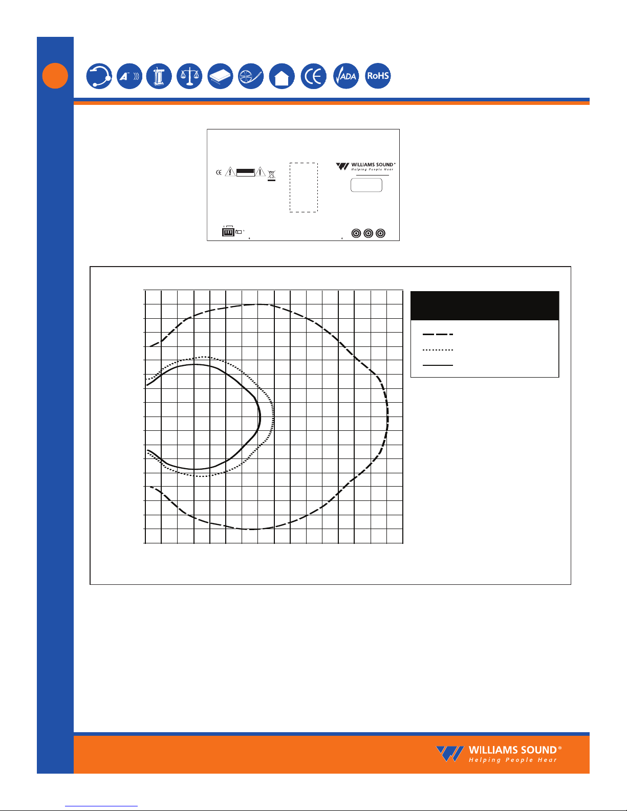
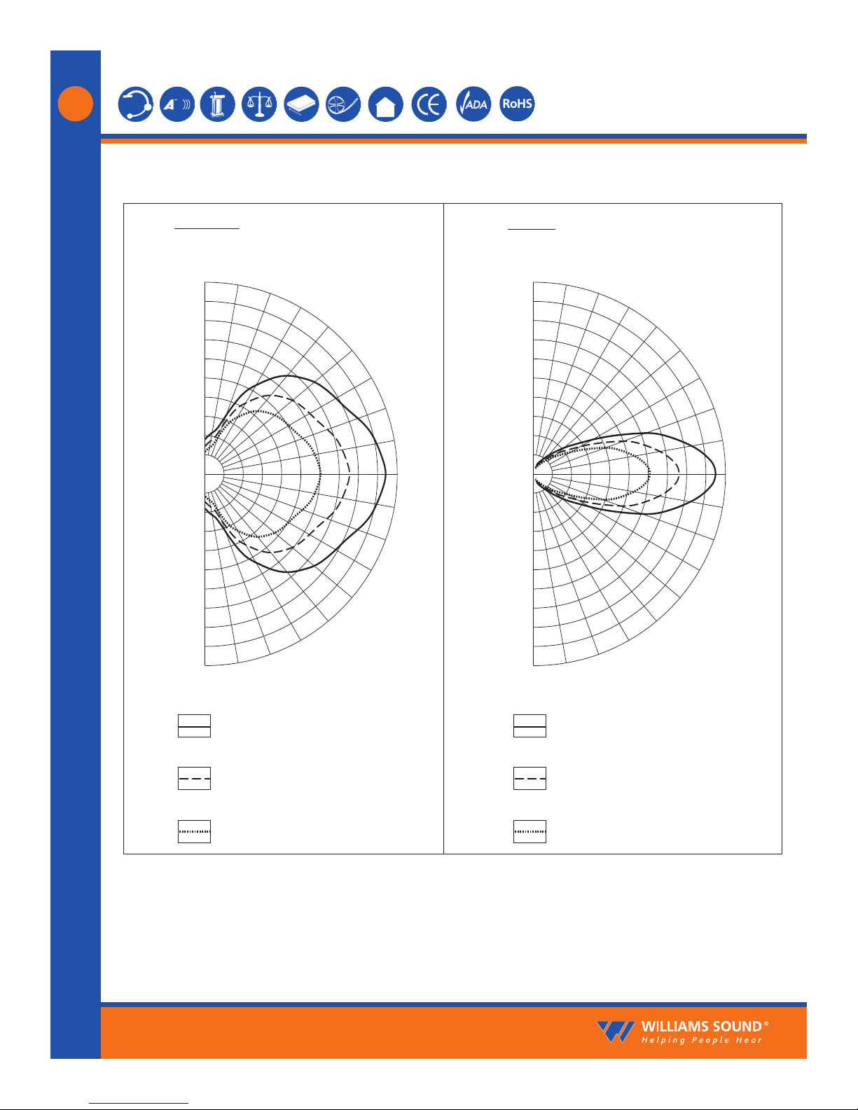
Coverage Area: Up to 28,000 ft2(2,600 m2)in single-channel mode when using the RX22-4 Receiver
Up to 18,000 ft2(1,700 m2)in two-channel mode when using the RX22-4 Receiver
Up to 3,500 ft2(325 m2)in single-channel mode when using the RX14-2 Receiver
Up to 3,063 ft2(285 m2)in single-channel mode when using the RX18 Receiver
(See coverage area diagrams)
Baseband Input: BNC, 100 mV per carrier, 50 Ω,for use with WIR TX9 or MOD 232 only
Baseband Output: BNC, 50 Ω,for use with TX9 only
Baseband Cable: RG 58 Coax, BNC connectors, maximum 1000' (300 m) length
Operating Requirements: 0-50º C ambient temperature, non-condensing, non-corrosive atmosphere
Mounting Kits: Wall or Ceiling Mount: BKT 024 Omnidirectional mount, Mic Stand Kit: SS-11 or SS-6
Warranty: 5 years on Emitter, 90 days on accessories
Approvals: CE, FCC, RoHS, WEEE
Compatible Receivers: WIR RX22-4 Four-Channel Receiver,RX14-2 Two-Channel Receiver,
RX18 Two-Channel Receiver
Configuration
Switches
Input CH A Input CH B
Audio Line
Output
CH A
CH A
CH B
CH B
50 Ohms
100 Ohms
Made in USA
24V
24 VAC, 15 VA, 50-60 Hz
Power In
Baseband
Input
Output
Output
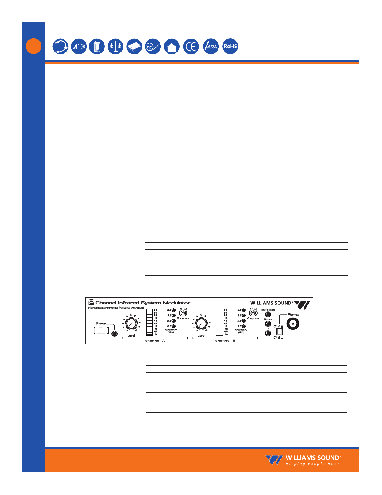
MOD 232 Infrared System Modulator
Plug
Williams Sound
12345678
12345678
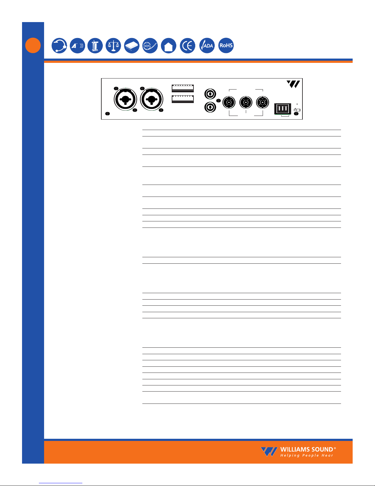
Fig. 2: MOD 232 Rear Panel
Power Input: 3-Pin Molex, 24 VAC, 50-60 Hz, 15 VA
Audio Input Jack: CHA and CHB combination XLR/TRS jack
Mic Level: Balanced, Lo-Z, 100 µV min. to 90 mV max., 1mV nominal, 3 kΩinput impedance, sup-
plies switchable simplex power per DIN 45596 for condenser mics
Line Level: Balanced or unbalanced, 21 mV min. to 10 V max., 212 mV nominal, 100 kΩ
Audio Line Output Jacks: RCA Jack, CHA and CHB, 500 mV, unbalanced, 100 Ωsource impedance, load imped-
ance must be greater than 1kΩ
Configuration Switches: CHA and CHB 8-position DIP switch, selects Mic/Line input, compressor gain, simplex
power, discrete or mixed inputs, carrier frequency, channel disable, auto shut-off
timer
Baseband Input Jack: BNC, allows mixing with additional MOD 232 Modulator (4CH operation), 100mV, 50Ω
input impedance, use with MOD 232, BNC, RG-58 Cable
Baseband Output Jack: Two BNC jacks carry baseband signal, 100 mV/channel, 50 Ωsource impedance, for use
with WIR TX9 or MOD 232 only
Approvals: CE, FCC, RoHS, WEEE
Operating Requirements: 0-50º C ambient temperature, non-condensing, non-corrosive atmosphere
Warranty: 5 years on modulator, 90 days on accessories
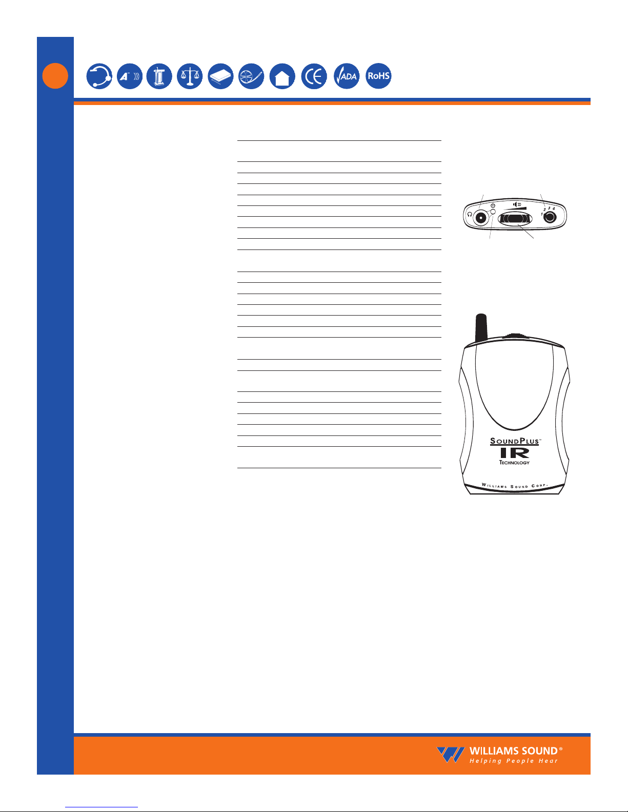
WIR TX9 Emitter: