English
24 WILO SE 07/2010
Observe the relevant, applicable regulations and
standards for using the potable water supply and/
or fire extinguishing supply. The installations
must be operated and maintained in accordance
with the relevant instructions (in Germany,
according to DIN 1988 (DVGW) so that the secu-
rity of the water supply is permanently guaran-
teed and neither the public water support nor
other consumption installations are detrimen-
tally affected. The relevant standards or direc-
tives (see Section 4 “Intended use” on page 22) on
connection and the type of connection to the
public water mains must be observed; and supple-
mented by regulations of water companies or
the responsible fire protection authorities, as
required. In addition, local conditions (e.g. a supply
pressure that is too high or fluctuates sharply and
which might require the installation of a pressure
relief valve) must also be observed.
6.2 Components of the system
The system is comprised of several main compo-
nents, which are described in the following. The
scope of delivery includes separate installation
and operating instructions for the operating parts/
components. (Also see attached installation plan.)
Mechanical and hydraulic system components:
Series CO-1 and COR-1 (Fig. 1a, 1b, 1d, 1e, 1f)
The system is mounted on a base frame with
vibration absorbers (1). It comprises a high-pres-
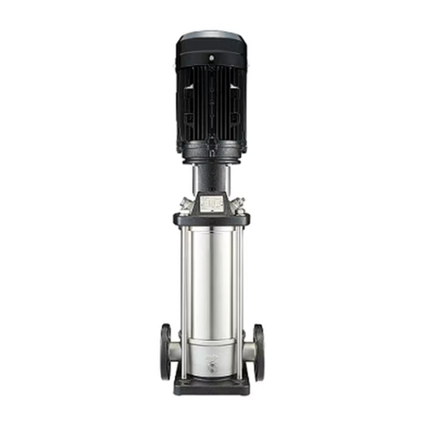
sure multistage centrifugal pump (2) with a
three-phase AC motor (3), with a stop valve (11)
and a non-return valve (10) on the pressure side.
There is also a unit that can be shut off containing
a pressure sensor or pressure switch (5)
(depending on the type of control device) and a
pressure gauge (15), and an 8 litre diaphragm
pressure vessel (4) with a throughflow fitting (6)
that can be shut off (for throughput according to
DIN 4807, part 5). As an option, a low-water cut-
out switchgear (WMS) (12) can be mounted or
retrofitted on the pump's drainage port or on the
inlet pipe. The control device (9) is mounted on
the base frame by means of an upright support
bracket and ready-wired to the electrical compo-
nents of the system.
Series CO/T-1 (Fig. 1c)
The system is mounted on a plastic baseplate (1)
belonging to the integrated break tank (7). It
comprises a high-pressure multistage centrifu-
gal pump (2) with a three-phase AC motor (3),
with a stop valve (11) and a non-return valve
(10) on the pressure side. There is also a unit that
can be shut off containing a pressure sensor or
pressure switch (5) (depending on the type of
control device) and a pressure gauge (15), and an
8l
itre diaphragm pressure vessel (4) with a
throughflow fitting (6) that can be shut off (for
throughput according to DIN 4807, part 5). Afloat
switch (Fig. 9) is installed in the break tank as a
signal transmitter for protection against low water
level. Water from the supply mains is fed into the
break tank via a level-dependent opening and
closing float valve (Fig. 10a and 10b).
The control device (9) is mounted on the tank by
means of a mounting plate and is ready-wired to
the electrical components of the system.
These installation and operating instructions
describe the overall system in general only, with-
out going into a detailed description of the opera-
tion of the control device (see section 7.3 and the
accompanying documentation for the control
device).
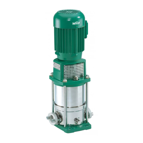
High-pressure multistage centrifugal pump (2)
with three-phase AC motor (3) :
Different types of multi-stage high pressure cen-
trifugal pumps are installed in the system depend-
ing on the application and the performance
parameters required. For information about the
pump, see the attached installation and operating
instructions for the pump.
Control device (9):
Different switching and control devices of differ-
ent types with different ranges of features can be
supplied and installed to activate and control the
system. For information on the control device
installed in this system, see the attached installa-
tion and operating instructions for the control
device.
Systems of series COR-1...GE do not have a sepa-
rate control device. The system is controlled by
the pump's integrated frequency converter
module. For operation and handling, see the
installation and operating instructions for the
pump.
Pressure sensor/diaphragm pressure vessel
assembly (Fig. 2a):
Included in systems of types CO-1.../CE+,
CO/T-1.../CE+, COR-1.../GE and COR-1.../VR
• Diaphragm pressure vessel (4) with throughflow
fitting (6)
• Pressure gauge (15)
• Pressure sensor (5)
• Electrical connection for pressure sensor (16)
• Draining/venting (17)
• Stop valve (18)
Pressure sensor/diaphragm pressure vessel
assembly (Fig. 2b and Fig. 3a or Fig. 3b):
Included in systems of types CO-1.../ER,
CO/T-1.../ER
• Diaphragm pressure vessel (4) with throughflow
fitting (6)
• Pressure gauge (15)
• Pressure switch (5) type FF (Fig. 3a) or type CS
(Fig. 3b)
• Electrical connection for pressure switch FF
(Fig. 3a) or pressure switch CS (Fig. 3b)
• Draining/venting (17)
• Stop valve (18)