7
• One, optional ow check valve (recommended for
parallel pumping systems, provided by Wilo).
• Installation and operation instructions (provided by
Wilo).
• Three wire nuts and three cable ties (provided by Wilo).
4.2 Installation
It is recommended that full port isolation ball valves be
placed on the supply and return lines for the pump so that
the pump can be serviced without having to drain the
system. Make sure that the pump is pumping away from the
bladder tank. Pumping toward the tank during extremely
low speeds, in rare cases, can cause the pump to become
air bound and stop the ow of water. It is recommended
that the system includes an air vent device at highest point
of the system.
• Install the pump in a vertical or horizontal position.
Refer to Fig.2a Horizontal Mounting and 2b Vertical
Mounting-Page 2
• Adjust the display to the proper orientation. The default
orientation for the display view is in the horizontal
position. In a vertical installation, remove the four hex
head bolts (4 mm) and turn the pump counterclockwise
90° and reinsert the hex bolts and tighten in a crisscross
pattern evenly until tight. Refer to Fig.2c-Page 2-
Rotating the Display.
• The installation and connection dimensions (connection
anges and pump footprint) are given in Fig.3-Page
3-Dimensional Data
• It is strongly recommended to capture sediment by using
permanent magnet separator upstream of the pump.
Using the supplied O-ring gaskets, install them on the
supply and return body anges of the pump, Tighten the
ange bolts evenly to the pump. Only use the O-ring
gaskets provided, any other gaskets used will void the
warranty. Refer to Fig. 5a-Page 4-Installing the Gaskets
The flow check option should be used when parallel
pumping is the primary piping conguration. When used,
please insert the ow check into the discharge neck until
it locks into place. Make sure the check moves freely. Refer
to Fig.2c-Page 2 - Rotating the Display.
WARNING! Risk of injury due to hot surfaces!
The pump must be positioned so that someone cannot
come into contact with the hot pump surfaces while in
operation.
If you are using differential temperature as the method of
control, zip-tie the probes to the supply and return piping.
Fig.4 -Page 3-Probe Location. If you have issues (e.g. not
enough wire length available to attach the probe to the
return piping), it is recommended to switch the control
mode from the Delta-T mode to the Auto mode.
This pump’s basic function is to pump hot or cold water or
water with 50% ethylene or propylene glycol.
NOTE: If introducing propylene or ethylene glycol into the
system, it is important to dose downstream of the pump.
DANGER! Risk of explosion!
The pump must not be used to pump ammable liquid such as
rapeseed oil and gasoline. Allowed liquids should be thin, clean,
non-corrosive and non-explosive and should not contain any
solid particles, ber or mineral oil.
4.3 Application areas:
Heating, Ventilation and Air-Conditioning:
• Boilers
• Induction heating
• Heat exchangers
• Temperature control systems
• Cooling circuits
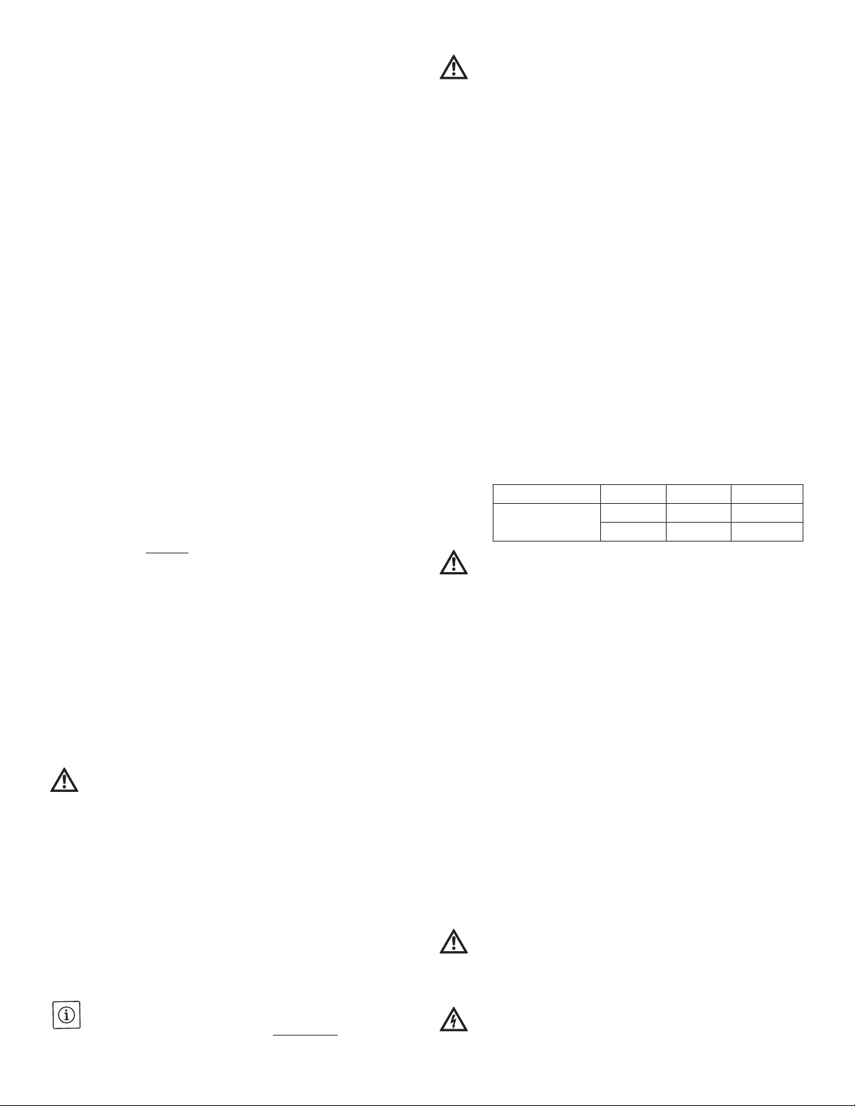
5. Technical data
5.1 Technical data
- Ambient temperature range: 0°F -104°F
- Max relative humidity: 95%
- Degree of protection: IP42
- Max ow: 14.5 Gallons Per Minute
- Max dBA: 42
- Max system pressure: 145 PSI (10 BAR)
- Fluid temperature range: 36°F -230°F
WARNING CONCERNING CONDENSATION
To avoid condensation in the control box and stator, the
temperature of the pumped liquid must be always higher than
ambient temperature . In cooling circuits it is recommended to
insulate the pump housing. DO NOT INSULATE THE MOTOR!
5.2 Motor Information
The Star E 21 pump is equipped with permanent-
magnet motor and differential temperature controller,
capable of automatically & continuously adjusting motor
performance to meet the actual needs of system.
5.3 Accessories
Original accessories are available for the Wilo-Star E 21.
The accessories must be ordered separately.
6. Electrical connections
Wire the pump from the boiler pump relay to the conduit
box. Note: Please follow the appropriate national and local
electrical codes. Two 3/4” knock-outs are available for
wiring; one on the side and one on the back. Liquid-tite,
BX, or Rigid conduit are the preferred methods to protect
the wiring. Fig. 6-page 4-Wiring diagram.
DANGER! Danger of death!
National Electrical Codes (NEC), local codes and
regulations must be followed.
WARNING! Electrical shock hazard!
All electrical work must be conducted by a qualied
electrician! Make sure that the supply voltages are
Installation and operating instructions - Wilo-Star E 21
Liquid Temperature <185°F 194°F 230°F
Minimum Inlet Pressure 0.725 PSI 4.1 PSI 14.5 PSI
1.68 Ft. of Hd 9.5 Ft. of Hd 33.5 Ft. of Hd