Wilson Electronics SX-530 User manual

SX-530
Disk Memory Exerciser
Operator's Manual
Copyright © 1981, WILSON
LABORATORIES, all
rights
reserved. Printed in the United
States
of
America
Document #
650074
RevE
November
1],
1981
WILSON LABORATORIES
reserves the right to change
specifications without notice
or
obligation.
WILSON LABORATORIES
2237 N. BATAVIA
ORANGE,
CA
92665
(714) 998-1980


SECTIONl .
INTRODUCTION
1.1
SCOPE
....................................................................
I-I
1.2
GENERAL.................................................................
1-1
1.3 PHYSICAL DESCRIPTION
...................................................
1-3
SECTION2
DISK
DRIVE
PRINCIPLES
2.1 SCOPE
.....................................................................
2-1
2.2
GLOSSARy................................................................
2-1
2.3 MAGNETIC DISK
STORAGE
PRINCIPLES
.....................................
2-2
2.3.1 Magnetic Disk Subsystem. . . .
..
.
..
..
. . . . . . . .
..
..
.
..
. . . . . . . . . . . . .
..
. .
..
2-2
2.3.2 Storage Medium
....................................................
2-2
2.3.3 DataCoding
.......................................................
2-3
2.3.4 Data Addressing
....................................................
2-4
2.3.5 Basic Operations
....................................................
2-4
2.3.6 Head Positioning. . . . . . . . . . . . . . . . . . . . . . . . . . . . . . . . . . . . . . . . . . . . . . . .
.. ..
2-6
2.3.7 Cylinder Detection
..................................................
2-6
2.3.8 Index Pulse
and
Rotational Speed Detection
..............................
2-6
SECTION3
EXERCISER
DESRIPTION
3.1
GENERAL.................................................................
3-1
3.2 FUNCTIONAL DESCRIPTION
................................................
3-1
3.2.1 Drive Connection
...................................................
3-1
3.2.2 Power Sequencing . . . . . . . . . . . . . . . . . . . . . . . . . . . . . . . . . . . . . . . . . . . . . . . . .
..
3-1
3.2.3 Drive Select/Status
..................................................
3-1
3.2.4 Seek Functions
.....................................................
3-1
3.2.5 Reset
......................
'.
. . . . . . . . . . . . . . . . . . . . . . . . . . . . . . . . . . . .
..
3-3
3.2.6
Form~tting
............
. . . . . . . . . . . . . . . . . . . . . . . . . . . . . . . . . . . . . . . . . . .
..
3-3
3.2.7 Format Timing
.....................................................
3-4
3.2.8 Skip
Track.
. . . . . . . . . . . . . . . .
..
. . . . . . . . .
...
. .
..
.........
..
...
....
. .
..
3-4
3.2.9
Write/Read.
. . . . . . . . . . . . . . . . . . . . . . . . . . . . . . . . . . . . . . . . . . . . . . . . . . . . .
..
3-4
3.2.
10
Data Patterns
.......................................................
3-4
3.2.11 Strobe and Offset Margin Testing. . . . . . . . . . . . . . . . . . . . . . . . . . . . . . . . . . . . .
..
3-5
3.2.13
3.3.14
Digital Display
.....................................................
3-5
Volume
...........................................................
3-5
Test Points
.........................................................
3-6
3.3 PHYSICAL DESCRIPTION
...................................................
3-6
3.3. i Consiruction. . . . . . . . . . . . . . . . . . . . . . . . . . . . . . . . . . . . . . . . . . . . . . . . . . . . .
..
3-6
3.3.2 Exerciser Assembly Removal
and
Re-installation
..........................
3-9
3.3.3 I/O Adapter Interface Card Removal
and
Reinstallation
.....................
3-9
iii

4.1 GENERAL
Drive Select
SECTION4
CONTROLS
AND
INDICATORS
Drive Status
......................................................
.
Index Sector
......................................................
.
Offset
...........................................................
.
StrolJe
...........................................................
.
Volume
..........................................................
.
Test Points
.......................................................
.
Seek Control
......................................................
.
Head Address
.....................................................
.
Address
Mark:
.....................................................
.
Write/Read
.......................................................
.
Data
............................................................
.
Reset
............................................
,
...............
.
Digital Infonnation Control
..........................................
.
Cylinder Address
..................................................
.
Errors
...........................................................
.
Action
...........................................................
.
SECTIONS
GENERAL
OPERATING
PROCEDURES
4-1
4-1
4-3
4-3
4-4
4-4
4-4
4-5
4-5
4-7
4-8
4-8
4-9
4-10
4-11
4-12
4-12
4-13
5.1
GENERAL.................................................................
5-1
5.2
TESTER CONNECTION
.....................................................
5-2
5.2.1
Procedure.
. . . . . . . . . . . . . . . . . . . . . . . . . . . . . . . . . . . . . . . . . . . . . . . . . . . . . .
..
5-2
5.3
SELECfDRIVE
............................................................
5-2
5.3.1
Procedure.
. . . . . . . . . . . . . . . . . . . . . . . . . . . . . . . . . . . . . . . . . . . . . . . . . . . . . .
..
5-4
5.4
SELECT INDEX SECTOR
....................................................
5-4
5.4.1 Procedure
..................
".
. . . . . . . . . . . . . . . . . . . . . . . . . . . . . . . . . . . .
..
5-4
5.5 BASICEXERCISER/DRIVECHECK
...........................................
5-4
5.5.1
Procedure.
. . . . . . . . . . . . . . . . . . . . . . . . . . . . . . . . . . . . . . . . . . . . . . . . . . . . . .
..
5-5
5.6
SET MAXIMUM CYLINDER ADDRESS
........................................
5-6
5.6.1
Procedure.
. . . . . . . . . . . . . . . . . . . . . . . . . . . . . . . . . . . . . . . . . . . . . . . . . . . . . .
..
5-6
5.7
SEEKOPERATIONS
........................................................
5-6
5.7. I Procedure-Manual Seek Operation,
No
Data
............................
5-7
5.7.2 Procedure -Manual Seek Operation, With Data
..........................
5-7
5.7.3 Procedure -Automatic Seek Operations
................................
5-7
5.8
FORMATTING
............................................................
5-11
5.8.1 Procedure -Fonnat All Tracks
.......................................
5-11
5.8.2 Procedure-Fonnat Single Track
.....................................
5-12
5.8.3 Procedure -Fonnat All Cylinders
On
Single Disk Surface
.................
5-12
iv

5.9
SKIPTRACK
..................
'
..........
~..
..
......
.....
......
.. ..
........
5-12
5.9.1 Procedure -SKIPFormat Single Track
................................
5-13
5.10
WRITE/READ OPERA
nONS
................................................
5-13
5.10.1 Data Patterns
......................................................
5-13
5.10.2
Procedure-
Write, Read, orWrite/Read
...............................
5-14
5.11 STOPON ERROR RECOVERY PROCEDURE
..................................
5-15
5.11.1
CYCLIC/SWITCHDATARecoveryProcedure..........................
5-15
5.11.2 RANDOM CYL Recovery Procedure
..................................
5-16-
5. 11.3 RANDOM PASS Recovery Procedure . . . . . . . . . . . . . . . . . . . . . . . . . . . . . . . .
..
5-16
5.12
HEADSELECfION-CMDDRIVE
.........................
;
.................
5-17
6.1
6.2
6.3
6.4
GENERAL
SECTION6
SELECTED
OPERATIONS
DISK SURFACE TEST-REMOVABLE
......................................
.
6.2.1 Procedure
........................................................
.
DISK SURFACE TEST-FIXED
.............................................
.
6.3. I Procedure
........................................................
.
RELIABILITY (BURN-IN) TEST
.............................................
.
6.4. 1 Procedure
........................................................
.
6-1
6-1
6-1
6-3
6-3
6-4
6-4
6.5 SEEK TIME READING
......................................................
6-5
6.5. 1 Procedure-Maximum Access Time
...................................
6-6
6.5.2 Procedure -Minimum Access SeekTime
...............................
6-6
6.5.3 Procedure -Average Access SeekTime
................................
6-6
6.6
SEEK ERROR RATE TEST
...................................................
6-6
6.6.1
Procedure.
. . . . . . . . . . . . . . . . . . . . . . . . . . . . . . . . . . . . . . . . . . . . . . . . . . . . . .
..
6-7
6.7
LOCATEALLBADTRACKS
.................................................
6-S
6.7.1
Procedure.
. . . . . . . . . . . . . . . . . . . . . . . . . . . . . . . . . . . . . . . . . . . . . . . . . . . . . .
..
6-S
6.S
FIND/VERIFY~BEROFBADTRACKS
.....................................
6-9
6.S.1
Procedure.
. . . . . . . . . . . . . . . . . . . . . . . . . . . . . . . . . . . . . . . . . . . . . . . . . . . . .
..
6-10
6.9
OPERATINGSX-530WITHALIGNMENTDISKPACKS
.........................
6-11
6.9.1 Procedure-Initial Setup
.....
. . . . . . . . . . . . . . . . . . . . . . . . . . . . . . . . . . . .
...
6-11
6.10
OFFSET MARGIN AND STROBE TIMING TEST
................................
6-12
v

LIST
OF
ILLUSTRATIONS
Figure
I-I SX-530DiskExerciser
........................................................
1-2
2-1
Head and CylinderAddressing. . . .
..
.
..
. . . .
.. ..
...
.......
.
.....
.
...
..
.
.. .. ..
. .
..
2-5
2-2 Head Positioning. . . . . . . . . . . . . . . . . . . . . . . . . . . . . . . . . . . . . . . . . . . . . . . . . . . . . . . . . . .
..
2-6
3-1
Typical Daisy Chained Disk Subsystem
.....
. . . . . . . . . . . . . . . . . . . . . . . . . . . . . . . . . . . .
..
3-2
3-2 Typical Subsystem with Drive 2 Removed for Testing
...............................
3-2
3-3 Typical Track
Format.
. . . . . . . .
..
. . .
...
. . . . .
..
. . . . .
...
. . .
....
.....
.. ..
.
.. ..
. .
..
3-3
3-4 Headerand Data Field Detail
...............................
~
. . . . . . . . . . . . . . . . .
..
3-5
3-5 SX-530 Exerciser
............................................................
3-7
3-6 Power Switch and Indicator Location . . . . . . . . . . . . . . . . . . . . . . . . . . . . . . . . . . . . . . . . . . .
..
3-8
3-7 Tester Assembly
.............................................................
3-8
3-8 Assembly Removal
....
. . . . . . . . . . . . . . . . . . . . . . . . . . . . . . . . . . . . . . . . . . . . . . . . . . . .
..
3-11
3-9 Nylon Standoffs and Latches
..................................................
3-11
4-1
SX-530 Control Panel
.........................................................
4-2
5-1
Head Selection for
CDC
CMD Drive
............................................
5-18
LIST
OF
TABLES
Table
3-1
SX-530I/OAdapters
........................................................
3-10
4-1
Illegal Operations
...........................................................
4-14
5-1
Static Control Panel. . . . . . . . . . . . . . . . . . . . . . . . . . . . . . . . . . . . . . . . . . . . . . . . . . . . . . . . .
..
5-3
vi

1.1 SCOPE
SECTION 1
INTRODUCTION
This manual describes the Wilson Laboratories' SX-530 Disk Memory Exerciser. The manual
is
written using
the storagemodule (SMD) type interface
as
the basis, however, interface adapteraddendums are includedas part
of
this document so the reader may easily adapt the methods described herein tootherdrive types supported by
the SX-530 Exerciser.
This manual consists
of
six sections and addendums
as
required and described briefly
as
follows:
Section I
Section 2
Section 3
Section 4
Section 5
Section 6
Addendum
Introduction and general desription including physical and environmental charac-
teristics.
A briefexplanation
of
disk drive theory to establish common terminology.
A functional and physical description
of
the
Exerciser including assembly and adapter
removal
and
reinstallation infonnation.
A description
of
the controls and indicators
in
a mannerso they
may
be easily found and
referenced.
General operating procedures
as
they relate
to
the
Exerciserfunctions and modes.
A group
of
suggested special procedures that
may
be perfonned during acceptance
testing and
field
maintenance applications.
Each addendum describes an 1/0 Interface Adapter Card for a specific drive type and
associated mini-panel assembly (as required). Also included are applicable operating
instructions
and
adiscussion
of
the
PROM
and
its
fonnat timing for that interface.
SX-530 Exerciser Theory
of
Operations and Logic Description
is
provided
in
a separate manual which can be
obtained from the factory
by
signing a non-disclosure letter ofagreement.
1.2 GENERAL
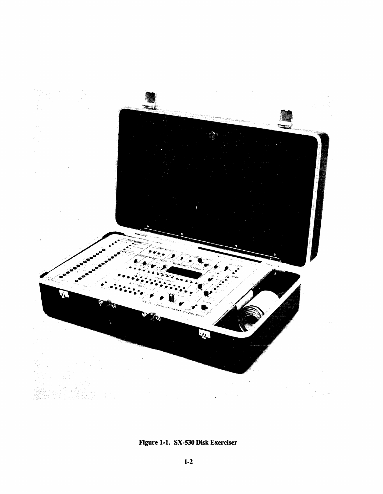
The SX-530 Disk Memory Exerciser, Figure
I-I,
is
designed
for
testing disk drive models with Storage Module
type interface and Winchester
fixed
andlor removable cartridge type disk drive
in
either
5JA",
8",
or
14"
media
from most manufacturers. It·can
be
used for all off-line drive exerciser/test functions including manufacturing
QC
testing
to
insure trouble-free operation before shipment,
QA
incoming inspection,
field
service testing to
isolate and repair drive problems
and
for engineering evaluation
of
peripherals.The SX-530
is
housed in a
suitcase type enclosure which makes it convenient for all applications.
The SX-530 reads and writes data
in
four fonnatted modes using a selection
of
three
fixed
data patterns and one
userprogrammabie data pattern. Errorindicators show
the
type
and
iocation
of
errors and manuai controis permit
single step orcontinuous running
with
error indication orstop
on
errorcapability.
Single steps, seek delay, alternate set, stop on error, offset
and
marginal strobe control combine
to
make trouble
shooting
by
t'le operator a quick and easy function. Trouble shooting operntion includes
the
ability to
intr"uduce
errors and check out specific areas
of
drive perfonnance.
1-1

1-2

Dri
ve
variations are accommodated
by
plug-in interfacecards and includethe following manufacturers' models:
• CDC SMD 9760/9762/9764/9766 and other SMD compatible interfaces such
as:
CDC CMD, MMD,
FMD
and LARK
FUJITSU
AMPEX 9300
AMPEXDFR
MICRODATA Reflex
MEMOREX
NEe
Storage Technology Corporation
• Kennedy 5300
• Trident T25{f50/T80/T200/T300 -BALL BD and BF Series
• PRIAM DISKOS 3350
• BASF 6170 Series -Disk Bus
• PERTEC 08000
• IMI 7700 Series
• ANSI
SID
X3T9
(8"
Hard Disk)
• SEAGATE ST506 and othercompatible
5~"
hard disks
• SLI
• SHUGART SA
1000
• Other compatible interfaces
1.3 PHYSICAL DESCRIPTION
The SX-530 Exerciser, a portable, off-linetesterdesigned to behandcarried,
is
contained in an attachecase with
a removable cover (see Figure
1-1).
The remaining base half contains the operator console and includes all
electronics.
When the Exerciser
is
not
in
use, the connected I/O cable and powercable are stored in the case along with extra
adapters, I/O cables and the manuals.
I/O Adapters are mounted on the underside
of
the Exerciser electronics board with positive locking standoffs.
Captive fasteners are utilized
to
allow quick console and electronics removal from the case for adapter and I/O
cable changes
to
accommodate different drive interface requirements.
The SX-530 Exerciser
physic~
characteristics are
as
follows:
• Size Length -
21
inches
Width -
13
inches
Depth - 7 inches
e W,:31lTht
"Y"""'.I.6.1.&"
12
pounds
• Power
100,
115/120, 200, 215, 230/240
VAC
50/60 Hertz
0.5 Amperes
• Temperature -o
to
45
degrees Centigrade non-condensing
• Electronics TTL Logic
• Timing Crystal Controlled
• Humidity
10%
to
95%
with
no
condensation
1-3


SECTION 2
DISK DRIVE PRINCIPLES
2.1 SCOPE
The
purpose
of
this section is to offer a common tenninology for all readers/users
by
briefly describing some
common
features basic to most types
of
disk drives.
The
discussion begins with a glossary
of
disk-associated terminologies, as employed in the manual, and
continues with general disk principles.
2.2 GLOSSARY
The
purpose
of
this briefglossary is to provide a common understanding
of
the terms.
ADDRESS
MARK
-An area
of
a track (usually 24 bits long) which is erased
by
the disk controller
by
means
of
a unique interface signal. Thiserasedareais detectedduring readbythedriveandactivates a
unique interface signal. The Address Mark feature is used by the controller for writing
"variable
sector" sectorformats on a track where the placement
of
the Address Markdetermines the beginning
of
each sector.
CELL
TIME
(or
BIT
CELLTIME) -The amount
of
time, atoperational speed, that the disk surface must
pass underthe heat to record
or
read back the flux reversals associated with one bit
of
data.
CYLINDER
-The selected, synchronous position
of
all heads ina diskdrive. Itis analogoustoservotrack
position; e.
g.,
if
Head0 is positioned overtrack 100, then all the otherheads are also positioned
over
theirrespective track 100's. Envisioningthese circulartracks ina vertical stackcreatesthe image
of
a
cylinder.
When
performing a seek, the drive is commanded to seek to a particular
"CYLINDER
ADDRESS," not to a track, perse. (See TRACK.)
DISK
(or DISK PLATTER) - A flat, circular plate, coated
on
both sides (surfaces) with some form
of
recording medium (usually iron oxide), which is used for storage
of
data.
DISK
MODULE (or DISK PACK) - A precision-assembled unit consisting
of
a varying number
of
disk,
arranged vertically.
It
may be permanently installed in the drive (fixed media),
or
of
the type which
may be removed and changed by the operator (removable media).
ERROR,
HARD -Permanent errors that occur at the same location
on
the disk surface during each test.
Typical hard errors are causedby drastic imperfections in the disk surface.
ERROR,
SOFf
-Intermittenterrors thatoccasionally occurwhen testing a disksurface. Generally caused
by minor imperfections in the disk coating
or
as a result
of
random electronic errors.
HEAD,
READ/WRITE -Electromagnetic devices which perform the actual recording
of
data onto,
or
reading
of
data from, the disk.
HEAD,
SERVO - A read head which reads head positioning information from the Servo Disk surface.
INDEX
- A reference point
or
"starting point" for eachdisk track. It provides initial synchronization for
sector addressing on each individual track.
MEDIA
-See DISK MODULE
MODIFIED FREQUENCY MODULATION (MFM) - A
"double
frequency" method for magnetic
recording
of
digital data, whereby flux reversal patterns are variable, depending
on
the data pattern.
This method provides a selfclocking capability.
2-1

NON-RETURN-TO-ZERO (NRZ) - A methodfor magnetic recording
of
digital data in whichthe levelat
each cell time denotes the logic state
(lor
0). This method requires a companion clock for definition
of
cell time.
RETURN
TO
ZERO SEEK(REZERO) - A disk drive function which results in the heads being retracted
to Cylinder0 regardless
of
the current location
of
the heads.
SECTOR
-The lowest-addressable-unit
of
storage in a disk drive, a sector is a portion
of
an individual
data track. The number
of
sectors per track is generally drive selectable and this number will,
of
course, determine the maximumdata storage capacity
per
sector.
SEEK
- A general term for the movement
of
the heads to any specific valid cylinderaddress (as opposed,
for example, to a
"head
retract").
SERVO
DISK -One
of
the disk module surfaces containing servo information prerecorded at the factory
to
be
used by the disk drive to generate head positioning information and various timing signals.
TRACK
-
The
completecircularportion
of
an individualdisk plattersurface overwhich a stationary head
is positioned at any given time. It is quite similar to a groove in a phonograph record, except that
instead
of
spiralling inward, the track is a concentric circle with respect to the circumference
of
the
disk. Tracks are not directly addressed as such; once all heads are at a given cylinder address, one
specific head is selected to read
or
write on the trackoverwhich it happens to be positioned.
VOLUME
-The highest-addressable-unit
of
storage within a disk drive. It may refer to a particulardisk
module, cartridge,
or
pack. In the CMD type drives, the removable cartridge is addressed as
"Volume
0,"
and the fixed module as
"Volume
1."
2.3 MAGNETIC DISK STORAGE PRINCIPLES
The
following explanatorydiscussion is meanttocoverthe mainprinciples, conceptsandterminologyrelative to
magnetic diskdatastorage in general.
In
the interest
of
brevity, however, concepts with a broad range
of
diverse
applications are covered to highlight only that aspect which is pertinent to the SX-530 Exerciser application.
2.3.1 Magnetic
Disk
Subsystem
A magnetic disk subsystem provides high-performance, high-capacity auxiliary data storage for the central
processor. Its ability for fast, direct access to specific areas
of
the storage medium, enables high speed data
storage
and
retrieval operations, making it ideally suited for a wide variety
of
processing applications.
A magnetic disk subsystemconsists
of
a controllerandone
or
morediskdrives (see Figure 3-1). The storage and
recovery
of
data by the magnetic disk subsystem is accomplished through the recording
of
information on, and
retrieval
of
information from, disk packs. The disk drive contains the rotational drive, access mechanism and
read/write components and circuitry to record data
on
and reproduce data from the disk pack. The controller
receives commands from the processor, and interprets them to initiate operations with the disk drives in the
subsystem. Datais then transferred between the processorand disk drive. Thecontrollerprovidesdatabuffering
to
relieve the processor
of
stringent timing requirements. The controller
also
provides the processor with the
status
of
both the controllerand that
of
all the attached diskdrives in the magnetic disk subsystem.
2.3.2 Storage Medium
The
storage medium used in a disk drive is disk pack. The disk pack, either fixed
or
removable, consists
of
multiple disks made
of
metal with a magnetic coating on both sides. The disks are stacked
on
a vertical hub.
Fixed
disk
packs contain all usable disk surfaces, therefore, a disk pack consisting
of
five disks will have
10 usable surfaces. Removable disk packs do not use the top
or
bottom disk surfaces.
In both disk packs, one
of
the usable disk surfaces contains servo positioning information prerecorded at the
factory. Hence, a fixed disk pack containing five disks has ten usable surfaces and nine data surfaces.
2-2

2.3.3 DataCoding
CodingMethods
The
most common method
of
data interfacing for data-processing applications
is
"Non-Retum-to-Zero" (NRZ
or
"change
on
one's").
The method
of
recording
is
Modified Frequency Modulation (MFM). In current
Winchestertechnology, data is recorded in MFM but the drive interface presents NRZ data.
RecordingFormat
The
format according to which data
is
recorded on the disk
is
detennined by the controller logic. Proper
formatting
of
the data is enabled and monitored using the index pulse. These consecutive pulses enable the
controller to format the data and signals the beginning and subsequent ending
of
all recording tracks at each
complete revolution
of
the disk pack. This index pulse is used to start the recording
of
data
on
the disks in the
form
of
sectors containing a number
of
records, with each record containing a number
of
bytes.
2.3.4 DataAddressing
To
be able to locate the exact same area on the disk pack repeatedly, each area on the disk pack must be made
unique. This
is
accomplished by adopting an imaginary cylinderconcept and assigning a horizontal and vertical
addressing scheme to it.
VerticalAddressing
Assume a disk pack has nine data recording surfaces (one additional surface contains servo data). Vertical
addressing is accomplished by assigning the numbers 00 through 08 to each
of
the nine data surfaces, in
consecutive order, from top to bottom (Figure 2-1).
HorizontalAddressing
Horizontal addressing
is
accomplished by assigning numbers to concentric circlesoneachdisksurface starting at
ofor the outermost circle. The concentric circles form the centers
of
recording tracks.
CylinderConcept
Ten
recording tracks having the same horizontal address designation, lie in the samecircular, vertical plane, and
can therefore be thought
of
as a cylindercontaining ten vertically aligned tracks. Hence, it is possible to address
data in any track (with the exception
of
the servo track) within any cylinder by positioning all the heads at that
particularcylinder and selecting the particularhead associated with the desired track.
\
Data Access
Every area on the disk pack can be accessed through the combined, straight line travel
of
the read/write heads
radially across the disk surfaces, and the 'rotational motion
of
the disks. Any track can be accessed specifying a
cylinderaddress and a head address.
2.3.5 Basic Operations
The purpose
of
the magnetic disk subsystem
is
to store information on the disk pack and to recover this same
information when needed at a latertime. Toenable the recovery
of
the storeddata, the subsystemmustbeable to:
1.
Control precisely where on the disk pack the information
is
to be recorded.
2. Return to the exact same location on the disk pack for recovery
of
the recorded information.
2-3

The
three basic operations
of
the subsystem therefore are:
1.
Seek.
2. Write.
3.
Read.
Although there are many commands used in conjunction with the magnetic disk subsystem, each command
normally causes the subsystem to execute one
or
more
or
a combination
of
these
three
operations.
2.3.6
Head
Positioning
The
read/write heads in the diskpackare supported by the rotational velocity
of
the disks in combinationwith the
aerodynamicproperties
of
the headpads. The resultantphysicaleffectis a highdensityairlayer, whichfunctions
as
an
air
bearingforthe headpadtorideon. Each headpadis connectedtoa headmounting arm(see Figure 2-2).
These
headassemblies are mountedtoa movable headstackcarriage. Anelectromagneticservocontrolledlinear
motor
or
equivalent device moves the carriage to position the heads at any
of
the cylinders.
Position andfeedback input to the carriage motoris derivedfrom information readfrom the servodisksurfaceby
the
servo read head. This information is recorded in specific patterns
of
flux reversals (dibits) that provide
positive detection
of
servo head positioning overa track.
The
heads are designated according to the corresponding disk surfaces,
i.e.,
head 00 is opposite recording
surface
00,
head 0 I is opposite recording surface 0
I,
etc. After the heads have been positioned at the desired
cy
linder, the headcarriage is held in place through electronic control bydetecting any positionaldeviation
of
the
heads and counteracting it electrically.
2.3.7 CylinderDetection
During the head positioning process the travel
of
the heads must be monitored. Every time the heads cross a
cylinder, this is registered, and the end result is then communicated to the controller. This means the drive does
notsignal every cylindercrossed
over-just
when it gets to the desired cylinder.
2.3.8 Index PulseandRotational Speed Detection
Each
track
of
the servo disk contains a pattern
of
missing dibits which is used to generate an index pulse. The
index pulse is used by the controlleras a homing pulse,
i.e.,
it indicates the beginning and subsequentending
of
all the tracks in the disk pack.
In addition, the index pulse is used by the disk drive itself to monitor the rotational velocity
of
the disk pack.
Attainmentand maintenance
of
this rotationai speed is extremely important
in
maintainingcorrectbitdensities in
the
tracks.
2-4

I
I
o
1
2
3
4
5
6
7
S
CYLINDER
o NO. N
1111111.1111111111111111111.111111
HEAD
AND
/SURFACE
NO.
SERVO "
RA!SED
TO
!LLUSTRATE
RECORDING
SURFACE
Figure2-1. Head and Cylinder Addressing
2-5
J
I

LINEAR
MOTOR
HEAD
STACK
CARRIAGE
(OR
EQUIVALENT)
r----
I
I
ARMATURE~---
<:
HEAD
MOUNTING
ARM
HEAD
PAD
d£o
SPINDLE
:>
Figure 2-2. Head Positioning
2-6
0
1
2
3
SERVO
4
5
6
7
./8
SURFACE NO.

3.1 GENERAL
SECTION 3
EXERCISERDESCRIPTION
This section contains both a functional and physical description
of
the
Exerciser. The functional description
orients the user to the operational capabilities
of
the
Exerciser. The physical description provides detailed
infonnationon the Exerciser'sconstruction leading to
how
to remove
and
reinstalltheOperator'sconsole
and
the
I/O adapter boards.
3.2 FUNCTIONAL DESCRIPTION
3.2.1 Drive Connection
As previously statedin Section 2, a
diSk
subsystemtypically consists
of
acontrollerand oneormore diskdrives.
Figure
3-1
illustrates a typical daisy chained subsystem. The controller is connected
to
Drive 1 through two
cables: adaisy chain (link) cable and asmaller
radial
cable.
The
remainingdrives
are
connectedtothecontroller
through a "linked" cable to
Driv~
1and a directly connected radial cable. The last drive
in
the sequence (Drive
4) must be tenninated.
"'
Adisk drive
to
be
tested with the SX-530Exercisermust
be
taken "off-line"tothe subsystem
as
showninFigure
3-2. The Exerciserconnects
to
asingle disk drive witheither
one
ortwo cablesdepending onthedrive types.
The
drive under test mustalso be
terminated.
The Exerciser tests a single drive at atime
as
it provides a single radial cable connection.
3.2.2 Power
S~uencing
Storage module (SMD) type drives typically have a Remote/Local switch which controls whether the drive is
powered
up
(spin up) from the drive or
the
controller.
In
the
Local position, the drive "power
on"
sequence is
started when the drive Start switch
is
pressed. In Remote position, the power on sequence is started when the
Start switch
is
pressed and sequence power ground
is
received from the controller.
The
SX-530 Exerciser
provides the sequencepowerground
by
"hard
grounding"
the
PickandHoldlines on
the
SMD
interfacecausing
the device
to
start the power
up
sequence.
3.2.3 Drive Select/Status
The drive number
is
manually selected
and
sets the signal level
on
the
drive's Unit Select lines. Drive status
is
constantly displayed
by
eight LEOs
on
the
Exerciser.
3.2.4 Seek
Functions
Prior
to
performing read and write operations,
the
drive
must
move
the
heads
to the desired position on the disk
surface. This
is
done by
the
drive servo circuits
in
response
to
Exercisercommands.
The Exerciser provides four basic seek
modes:
1.
Set
2. Increment
3. Decrement
4. Random
3-1

DRIVE
1 DRIVE
2
CONTROLLER
DRIVE
3
A =
LINK
OR
DAISY CHAIN CABLE CONNECTION
B =
RADIAL
CABLE CONNECTION
T =TERMINATOR PLUG
DRIVE
1
SX-530
EXERCISER
FigUre3-1. Typical
DUy
CbaInedDIskSubsystem
DRIVE
2
LINK
CABLE
CONTROLLER
DRIVE
3
RADIAL
CABLE
Figure
3-2. Typical Subsystem withDrive 2 Removed for Testing
3-2
DRIVE
4
DRIVE
4

Seek action may
be
selected without
n~ta
action. When
combine.d
wit..l}
data action,
t..l}e
seek action will always
precede the data action.
In the Set (manual) Mode, repeated seeks
to
a user selected cylinder address will be made.
In the Incrementing Mode, the seeks are performed from one cylinder address
to
another sequentially until a
maximum address
is
reached at which time the address returns
to
zero
and
the
incrementing pattern
is
repeated.
The Decrement Mode
is
the reverse ofthe Increment Mode.
Random seek operations are facilitated
by
high speed counting
of
the
address registerbetween seek actions thus
generating random seek addresses.
Each
of
the four seek modes can be modified
by
the Alternate
Mode
thus providing seek action between a fixed
address (alternate) and the selected mode address. A Seek Delay feature providing variable delay up to 3.0
seconds
is
included to slow
the
action
to
allow visual monitoring
of
seek operations. A Seek Off control
is
provided
to
allow writing
and
reading without seek action. Switches and indicators are provided to set the
maximum and alternate cylinder addresses
up
to
2047.
3.2.5 Iteset
Provisions have been included
for
manual generation
of
cylinder rezero and fault clear commands and for
automatic resetting
of
fault and seek error occurrences.
3.2.6 Formatting
Formatting
is
the writing
of
both the header and
the
data
fields
by
the
Exerciser on a selected track.
If
the drive
and the media are
to
be completely tested, then all tracks (the combination
of
all cylinder addresses and all head
addresses) must first be formatted. Write orread action attempted
by
the
Exerciseron any track thathas not been
formatted
by
the Exerciser
will
result
in
data and/oraddress errors. The general format
of
atrack
is
illustrated
in
Figure 3-3. Data patterns are defined
in
paragraph 3.2.10. The details
of
the header and data field are shown
in
Figure 3.4
INDEX
~
VALID
DATA
1t
HEADER
READ
FORMAT
+
IDLE
TIMES
..........
__________________
~I
i~
__________________
__
HEADER
HEADER
HEADER
&
DATA
FIELD
n+1
~
~
I
L
WRITE
DATA
mm
mm
cr
....
1---1
......
.&....
.......
..-.._
----~A~~~~======~1I1
j I I I I I I I I I I I I I I I I I I I
~
16 -
BIT
DATA
FRAME
UJ~Ux
z'x
j'
~
5
~
~
i
~
i 14 12 10 8 6 4 2
01
u 0 I I I I I I I I I I I I I I I I I
~~
CYLINDER
15131197531
en
("\
I\nnD""C"C"
::i
I
HEAD'
Muunc;;,;J,;J
I
ADDRESS
FIRST
19 BITS
SELECTED
~DATAPATTERN~
Figure 3-3. Typical Track Format
3-3

3.2.7 FormatTiming
The
timing relationships for the data format oneach track depends on the particulardrive undertest as the timing
is determined by the PROM installed in the adapter board. The PROM coding determines the byte count as
measured from the index
forO
the location of:
•
Two
write gate enables
•
Two
read gate enables
•
Two
write sync bytes
• Write address mark
Two
counts for each
of
the write gate enables, read gate enables, and write sync byte are needed because the
format consists
of
both a single header and a second header followed by a single data field which continues to
index.
The
spacingbetweenthe write gate enablecountand the write sync byte countis the length
of
the all-zeros
preamble. The write data following the sync byte is not PROM changeable and is always the format shown in
Figure 3-4. The Address Mark selection may also modify the write gate, read gate, and sync bit location.
3.2.8 SkipTrack
The
SKIP
feature allows a known bad track to be read without flagging either an Address
or
a Data error. The
desired track is formatted to add a bad track bit to the header pattern.
If
the bad track bit is detected when the
headeris read, then the errorflagging is inhibited for the entire track.
3.2.9 Write/Read
In addition to the formatting mode, the Exerciserprovides
three
modes
of
WRITE/READ
action:
READ:
WRITE:
WR/RD:
This function reads the headerand reads the data field
~------------------------------------------Nou----------------------------------~
In all Read actions, the
18
bits
o/header
andall
o/the
data field up to
indexare bitby bitcompared/orerrorafterSYNC is/ound.
This function reads the header field and writes the data field.
(Write/Read) This function first reads the header and writes the data field, then rereads the
header and reads the data field.
3.2.10 Data Patterns
Three data sources are selectable for data transfer operations:
1.
Cyclic - a continuously varying 16-bit pattern uniquely different for each track.
2. Random cylinderand pass - a
16
bit random data pattern generated by high speed counting.
3. Switch -user selected data through the
16
data switches.
The
Random data pattern
is
user selectable by pass
or
by cylinder. The Random Pass data pattern provides a
unique datapattern foreachpass through all cylinders and heads. Eachpass consists
of
first writing thepatternon
all tracks then reading from all tracks. The data pattern is then changed and the next pass
is
run. Random by
Cylinder pattern provides a unique data pattern for each cylinder.
3-4
Table of contents
Other Wilson Electronics Fitness Equipment manuals