Wilsonart LinkCharge CT User manual

WILSONART® Solid Surface
WILSONART LINKCHARGE™ CHARGING STATION
Revised 2022 Copyright Wilsonart.

Any fabrication procedure or technique not contained within the Wilsonart® Solid Surface
Fabrication Manual will not be recognized by Wilsonart, LLC as an approved method of
fabrication. Deviations from these techniques must be approved in writing by a Wilsonart
Representative.
INTRODUCTION

General Safety:
Safety is a critical concern for any shop and key to a successful business. The following safety rules should be
incorporated into your safety program to help prevent an accident. Safety training,
knowledge, product use and environment are the responsibility of the facility owner and the shop
employees.
Figure 4A
Figure 4B
• Read directions carefully before fabricating/installing Wilsonart®
Solid Surface.
• Read and follow the instruction manual before operating the
dierent tools.
• Keep all guards in place and in working order.
• Ensure all tools are properly grounded. Never remove the third
prong.
• Keep work area clean, uncluttered and well lit.
• Don’t use electric power tools in a damp or wet
work area.
• Keep visitors at a safe distance from the work area.
• Use the right tools. Don’t force a tool or attachment to do a job it
was not designed to perform.
• Always use safety glasses or approved eye protection and/or face
shield, ear/noise protectors and safety shoes. (FIG. 4A & 4B)
• Wear the proper apparel, no loose clothing or jewelry.
• Secure all work with the proper clamp or vise to a stable work
surface.
• Don’t overreach. Keep proper footing and balance at
all times.
• Maintain tools in top condition. Disconnect tools before servicing
and when changing accessories such as blades, bits, cutters, etc.
• Keep and use denatured alcohol, adhesives and materials in a safe,
ventilated place.
• Dust collection should be used when cutting, routing and sanding.
Tools should be used with dust collection at all times.
CAUTION: Always follow product, equipment and/or tool
manufacturer’s recommendations and instructions carefully.
SAFETY

Figure 5A
Wilsonart® Hard Surface Adhesive:
• Wilsonart® Hard Surface Adhesive is for professional use only. Always follow the
manufacturer’s recommendations and instructions carefully. (FIG. 5A)
• Warning: This seam kit contains the following hazardous ingredients: Methyl Methacrylate,
Benzoyl Peroxide, and Dibutyl Pathlate. Avoid prolonged breathing of vapors. Use only in a well
ventilated area. Keep out of reach of children. Eye protection is always recommended. Motors
and other equipment used in the fabrication and installation process must be UL labeled
explosion proof.
• For further information refer to Wilsonart® Hard Surface Adhesive Material Safety Data Sheet
available on request. Contact your local distributor or
call 1-800-433-3222 for immediate response.
SAFETY
FAB TIP:
• For Wilsonart Solid Surface hard seam design color chart, refer to www.wilsonart.com

INTRODUCTION
Product Information:
Wilsonart Engineered Charging Surfaces becomes the solid solution when the need to charge your wireless
Smart Phones or Smart Pads. There are several charging options to pair Wilsonart Engineered surfaces with
in the market today, the following are Wilsonart's recommends with Laminate, Solid Surface, and Compact
surfacing products in residential and commercial applications.
Product Charging Descriptions:
LinkCharge™ - CT Infrastructure Wireless Charging System
This infrastructure transmitter module is a complete self-contained system and contains a custom controller
for managing the Qi or PMA protocol and charging functions. During the pairing process with a WPC Qi 1.2
compatible receiver above the transmitter coil, the module implements a WPC 1.2.1 wireless system with
power output up to 15W.
The transmitter will automatically adjust the charging power, based on the requirements of the receiver.
• Supports Qi, PMA and proprietary charging applications
• Power output up to 15W
• Easily mounts under counter or in most non- metallic furniture surfaces
• Determines correct wireless power protocol depending on the receiver
• Requires a 19V @ 2A DC input supply
• Can be daisy-chained on a single power supply for multi-site charging
• LED indicators for power on, charging and error conditions
• PMA SR1 compatible
• Compatible with fast charging phones
• 15W power output
• Charges portable devices through up to 10 mm of material thickness
Features
LinkCharge™ - CT Infrastructure Wireless charges portable devices through up to 25/64” (10 mm) of material thickness.
Minimum Spacing
Specifications

GENERAL SAFETY
Safety is a critical concern for any shop and key to a successful business. The following safety rules should be incorporated
into your safety program to help prevent an accident. Safety training, knowledge, product use and environment are the
responsibility of the facility owner and the shop employees
Safety Guidelines:
Dust mask must be worn at all times and always follow U.S. regulations for proper ventilation - Wilsonart Wireless Charging
Station dust contains silica which can be hazardous to one’s health. Always shape and cut material with wet tools,
reducing the amount of airborne particles to be inhaled.
Protective Wear:
Wearing an approved face mask is recommended when fabricating Wilsonart Wireless Charging Station. Wilsonart Wireless
Charging Station dust contains silica, which is dangerous when inhaled. Always cut and polish Wilsonart Wireless Charging
Station with wet diamond tools and take appropriate measures to provide ecient ventilation in the work area.
• Read Wilsonart Wireless Charging Station Installation Guide carefully before fabricating or installing Wilsonart
Wireless Charging Station.
• Refer to Wilsonart Wireless Charging Station SDS sheet at www.wilsonart.com or click here for detailed information
regarding material composition, precautions and other critical safety information before handling or fabricating
Wilsonart Wireless Charging Station.
• Always use safety glasses or approved eye protection and/or face shield, ear/noise protectors, and protective
work gloves.
• Dust mask must be worn at all times and always follow U.S. Regulations for proper ventilation.
• Always use safety toe work shoes.
• Always follow product, equipment and/or tool manufacturer’s recommendations and instructions carefully.
• Keep all guards in place and in working order.
• Insure all tools are properly grounded, don’t use tools in dangerous environments. Never remove the third prong and
be cautious with tools exposed to water and moisture.
• Keep work area clean, uncluttered and well lit.
• Keep visitors at a safe distance from the work area at all times when installing Wilsonart Wireless Charging Station.
• Use the right tools. Don’t force a tool or attachment to do a job it was not designed to perform.
• Wear the proper apparel, no loose clothing or jewelry.
• Maintain tools in top condition. Disconnect tools before servicing and when changing accessories such as blades, bits,
cutters, etc…
• Secure all material with the proper clamp or vise to a stable work surface.
• Don’t overreach. Keep proper footing and balance at all times.
• Keep and use denatured alcohol, adhesives and materials in a safe, ventilated place.
CAUTION

GENERAL SAFETY
Hazards Identification:
Potential Health Eects Include
Acute Eye: Product in finished form does not present a health hazard via this route of entry. Dust and flying particles
generated during cutting, grinding and forming may cause irritation and injury
• Acute Skin: Dust generated from this product may cause skin irritation.
• Acute Ingestion: Not considered a potential health hazard via this route of entry. This product may cause
gastrointestinal irritation if dust is swallowed.
• Aggravation of Pre-existing Conditions Not Determined.

INSTALLATION
Electromagnetic Considerations:
Locate the charger at least 1” (25 mm) from any support structure. Assure that no metal is present above the transmitter
unit. Provide at least 11/2” (36 mm) of clearance above the charger, and 1” (25 mm) below the unit. If multiple chargers are
present, allow at least 6” (150 mm) spacing between each.
Identifying The Location of The Charging Point:
Since ecient power transfer relies upon close coupling of the receiver with the transmitter, it is important that the user be
able to accurately locate their handheld device directly above the transmitter for charging. As such, consideration should
be given to providing some form of location guide on the counter top. The prominence and styling of these visual guides
is a matter of installer preference, and should take into consideration the needs of the end user. In a setting where the
installation will be well known to a limited number of users, a subtle or even temporary location guide may be sucient.
In settings where users won’t be familiar with the location of the charging site, a more prominent marking would likely be
preferred, both to identify the availability of the site and the optimal placement for the handheld device to be charged.
Mechanical Details:
The charger should be mounted to the underside of a counter top. The installer should verify that the power and micro USB
ports are accessible after installation, and should plan for the routing of the DC power supply cable. The installer should
also plan for the mounting of the included power transformer. Lastly, the installer should plan for the routing of the AC cable
from the transformer to an available AC outlet.
Routing:
The transmitter coil must be located between 1/4” - 5/16” (6 and 8 mm) below the top of the counter to provide the correct
transmitter to receiver spacing. In most cases, this will require milling a cavity into the underside of the counter into which
the charger can be mounted to achieve the correct spacing.
FABTIPS: Avoid putting transmitter near locations where the device being charged may get wet, exposed to
heat or other conditions which may damage charging device.
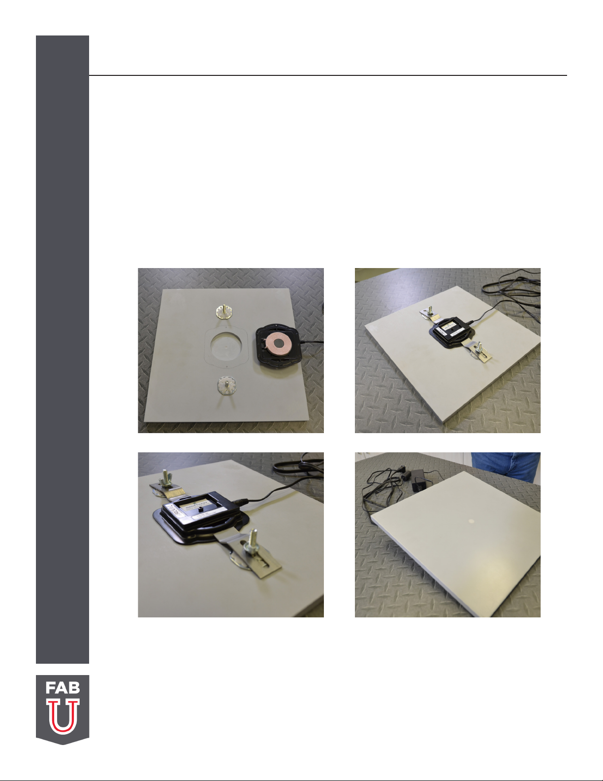
After the pocket is milled out, test-fit the charger and verify that there will be clearance for the power and USB connections.
Testing the Charger:
Before installing the transmitter, verify its functionality:
1. Apply power and check to see that the green LED blinks once.
2. Place a 1/4”- 3/8” (6 to 10 mm) spacer above the charger coils: - spacer can be made of any non-metallic material
desired, e.g.: plastic, wood, cardboard, etc.
3. Place a compatible handheld device over the spacer and verify that the device indicates charging has commenced.
FABTIPS: Never place a receiver in direct contact with the transmitter coil. The minimum allowable spacing is
1/4” (6mm). Placement closer than this could damage the receiving device and must be avoided at all times.
Once installed, this concern is eliminated, but the installer must take this concern into account when testing
the device prior to installation.

INSTALLATION
Mounting:
Clean the milled area along with the surface the transmitter flange will sit with a white cloth dampened with denatured
alcohol. The flange will set slightly above the surface when the coil is in contact with the cavity surface. Attach the
transmitter to the solid surface with 100% silicone adhesive. Place dime size dabs at each corner. Use clear or translucent
adhesive, avoid contrasting or dark colored silicone. Hot melt adhesive may be used to hold the transmitter in place while
silicone cures.
Rotoloc stems, sink clips, wing nuts and WA Solid Surface adhesive can be used for a more permanent mount. Clean the
milled area along with the surface the transmitter flange will sit with a white cloth dampened with denatured alcohol.
Two Rotoloc stems will be enough to securely mount the transmitter. Use a colored matched WA Solid Surface adhesive
and apply a quarter sized dab to each location. Place each Rotoloc on top of dabs and slightly press into adhesive. Allow
adhesive to cure. Use sink clips and wing nuts to secure the transmitter.
WIRING:
The transmitter kit includes a power supply compatible with the charger. If a volume purchase did not include the supply,
one must be obtained that meets the following specifications: 19 +/-1.5 V DC input supply, 1.32 A (or greater) with a plug
at the end of the DC line. See FIgure 10A
When planning the mounting the transmitter, attention should also be given to how the power cord(s) will be routed.
While the cord could simply be plugged into the charger and allowed to drape to the floor, embedding the cord within
the counter or attaching it to the underside of the counter should allow for greatly improved ergonomics, reliability, and
aesthetics. It may be optimal to cut a shallow channel into the underside of the counter to route the cabling through, so as
to minimize the chance of the cord interfering with anything below the counter. This is not a consideration unique to this
charger, so the installer should determine the cable routing as they would any other similar power cable.
Figure 10A

INSTALLATION
LED Indicator:
The LED present on the side of the transmitter indicates the state of the device. During device test, it can easily be
observed, but when mounted beneath a countertop it is not normally visible. If desired, the installer could use a length of
fiber optic cable to route the light from the LED to a location visible after installation. Normally, the device being charged
will display the charging status, so the need for status provided by the transmitter LED may be redundant. Below is a table
defining the various LED displays:
No Light Charger O or Standby
One Green Flash Power Applied, Device Initialized
Continuous Flashing Green Light Charging Cycle Underway
Steady Green Light Charge Complete
Flashing Red Light Foreign Object in Charging Field -
Remove Object, Restart Charging
Steady Red Light Error- Remove and Replace Receiver
Table of contents