WilTec 62549 User manual

User’s manual
Arc Welder
62549
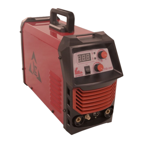
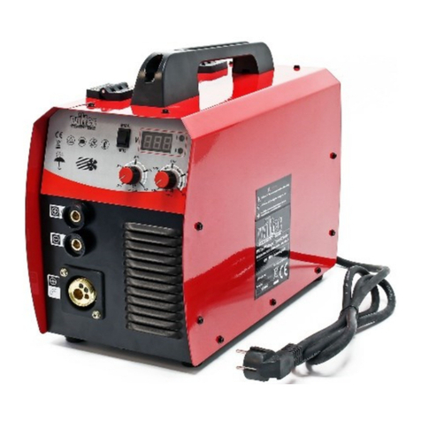
Illustration similar, may vary depending on model
Please read and follow the operating instructions and safety information prior to initial operation.
Technical changes reserved!
Illustrations, functional steps, and technical data may deviate insignificantly due to continuous further
developments.

© by WilTec Wildanger Technik GmbH Item 62549 Page 2
http://www.WilTec.de
http://www.aoyue.eu 01 2022-1
http://www.teichtip.de
The information contained in this document may alter at any time without prior notice. No part of this
document may be copied or otherwise duplicated without prior written consent. All rights reserved.
WilTec Wildanger Technik GmbH cannot be held liable for any possible mistakes in this operating man-
ual, nor in the diagrams and illustrations shown.
Although WilTec Wildanger Technik GmbH has made every possible effort to ensure that this operating
manual is complete, accurate, and up-to-date, errors cannot be ruled out entirely.
If you have found an error or wish to suggest an improvement, we look forward to hearing from you.
Send us an e-mail to:
or use our contact form:
https://www.wiltec.de/contacts/
The most recent version of this manual in several languages can be found in our online shop:
https://www.wiltec.de/docsearch
Our postal address is:
WilTec Wildanger Technik GmbH
Königsbenden 12
52249 Eschweiler Germany
Do you wish to collect your goods? Our address for collection is:
WilTec Wildanger Technik GmbH
Königsbenden 28
52249 Eschweiler Germany
In order to shorten the waiting time and to allow for an easy on-site processing, we kindly ask you to
contact us briefly beforehand or to place your order via the webshop.
E-mail: service@wiltec.info
Tel: +49 2403 55592–0
Fax: +49 2403 55592–15
To return your goods for exchange, repair, or other purposes, please use the following address. Atten-
tion! To allow for a trouble-free complaint or return, it is important to contact our customer service team
before returning your goods.
Retourenabteilung
WilTec Wildanger Technik GmbH
Königsbenden 28
52249 Eschweiler Germany
E-mail: service@wiltec.info
Tel: +49 2403 55592–0
Fax: +49 2403 55592–15

© by WilTec Wildanger Technik GmbH Item 62549 Page 3
http://www.WilTec.de
http://www.aoyue.eu 01 2022-1
http://www.teichtip.de
Introduction
Thank you for choosing to purchase this quality product. To minimise the risk of injury, we ask you to
always take some basic safety precautions when using this product. Please read this operating manual
carefully and make sure that you understand it.
Keep these operation instructions in a safe place.
Safety instructions
Carefully read the information and safety instructions found within this instruction manual and adhere to
them to ensure an ideal mode of operation while at the same time minimising the risk of accidents. The
instructions found in this manual thereby do not replace rules and regulations applying at your workplace
and instead complement them. Keep this manual and make sure it is in reach when working with this
product.
General safety
•Only qualified technical personnel may perform repair and in-depth maintenance work on this
device and its electric components.
•Make sure that the device has been properly turned off and disconnected from its power supply
before cleaning it or performing any repairs and maintenance.
•The device must always be disconnected from its power supply when it is not in use and ensure
that it is safely stored in a place unavailable to children.
•Always be vigilant when operating this device and do not operate it while being tired or under
the influence of alcohol, drugs, or medicine.
•Never use the device without its covers being in place.
•Keep your working area clean and well illuminated. A cluttered and poorly lit workplace in-
creases the risk of accidents.
•Never use this device in environments containing flammable or explosive substances, liquids,
or gases as these might be ignited.
•Check the device before each use to know if connections are correct.
•Do not expose the device to rain, any other sources of water or environments with a high level
of humidity.
•It is advised to place the device on even surfaces, but it can safely be placed on surfaces with
an inclination of up to 15°. Be aware that the device requires a secure stand and that its wheels
need to be blocked to prevent the device from moving, if not used on even surfaces.
•Do not use the device if the power chord is damaged or shows signs of wear, and never try to
repair a damaged power chord. Instead have it replaced by qualified technical personnel.
•This device must not be used by persons with reduced physical, sensory, or mental capabilities,
or lack of experience and knowledge. Children in the vicinity of the device should be always
supervised to ensure that they do not get too near or try to operate it.
•Do not use this device for thawing pipes.
•Do not use rusty wires as its rough surface might damage the device.
•The device should only be connected to the mains via a 20 A load break switch.
•The device must not be used, if parts or components show signs of damage or wear; replace
the worn or damaged parts before operating the device again.
•In addition to the instructions in this manual, you must obey the legal general safety and accident
prevention regulations.
Fire protection
•Remove all flammable and explosive materials from the working area as well as its close vicinity
in before operating this device.
•Do not weld fuel tanks or similar containers for explosive or flammable substances, if these have
not been cleaned duly and it cannot be guaranteed that they are free from remnants such as

© by WilTec Wildanger Technik GmbH Item 62549 Page 4
http://www.WilTec.de
http://www.aoyue.eu 01 2022-1
http://www.teichtip.de
residual gases. Fuel tanks should be thoroughly cleaned with a steam cleaner before any kind
of welding work can be performed on them.
Personal safety
•Always wear welding gloves when operating this device to protect your hands from the direct
heat of the arc as well as the UV radiation emitted by it.
•When working with higher settings, make sure to wear a special leather apron for additional
protection from possible spatter.
•Do not look into the arc with your eyes unprotected. Only use welding protection shields with
protective glass according to DIN. The welding shield must always be used during welding. It
protects your eyes from harmful ultraviolet radiation and heat emitted by the welding arc.
•When performing overhead welding, a closed welding helmet with adequate neck protection
must be worn.
•It is generally advised to wear an overall as well as safety shoes with steel toe caps when
welding.
First steps
Ensure that your MIG welder is earthed and connected to a suitable switch disconnector. The wiring
should thereby be as follows:
•brown = phase conductor
•blue = neutral conductor
•green/yellow = earthing
Installing a new wire reel
1. Remove the chassis of the welder and carefully unfasten both, the power nozzle and as well as
the burner nozzle.
2. Then attach the wire reel. Ensure that the spring is placed properly before fastening everything.
3. Check the feed roller and ensure that the size depicted on its top corresponds to the size of the
wire you intend to use. It might be necessary to reverse the feed roller. To do so you must
loosen its support by removing the fastening screws and the bracket. The feed roller can now
be removed and reversed.
4. Search for the loose end of the wire, which should be placed in a hole on the rim of the reel,
and remove deformed parts with the help of a wire cutter to ensure that the wire will not jam in
the process of welding. Make thereby sure that the wire does not come undone from the reel.
5. Hinge the pressure control away and insert the wire into the opening. Thereby ensure that the
wire is inserted in a straight line and that the feed mechanism can pull it in.
6. Return the pressure control to its original position. Make sure to choose the right size for the
wire (0.6 mm or 0.8 mm) and that the wire is placed in its niche accordingly.
7. Turn on the main switch of the device and press the trigger of the burner to cause the feed
mechanism to pull the wire through the hose and burner.
8. As soon as there is a wire excess of 1–2 cm sticking out of the burner, let go of the trigger and
turn off the device.
9. Carefully reattach both power nozzle and burner nozzle. When reattaching, check that the size
of the power nozzle corresponds to the wire size.
10. Reattach the chassis and fasten it.
Caution: Always make sure to completely unfold the hose connecting the burner and the main body of
the welder when feeding wire as the moving wire might otherwise damage the hose by puncturing it
from the inside.

© by WilTec Wildanger Technik GmbH Item 62549 Page 5
http://www.WilTec.de
http://www.aoyue.eu 01 2022-1
http://www.teichtip.de
Mounting the gas cylinder
1. At first, make sure that the valves of the bottle (if available) as well as the valve of the regulator
are completely closed (turned clockwise) to avoid a loss of gas due to accidental leaking.
2. Attach the high-pressure hose to the rear of the welder before connecting the other end to the
pressure regulator. To remove the hose, simply press it as well as the locking ring against the
hose connector. Keep pressing the ring in that direction and remove the hose by carefully pulling
it off the connector.
3. Ensure that your eyes are protected before removing the protective cap of the gas cylinder and
carefully attaching the regulator valve as gas might leak from the cylinder until the regulator
valve is attached properly.
4. Make sure to disconnect the regulator valve from the gas cylinder and to replace it with the
protective cap of the cylinder to prevent a loss of gas.
Configuring the regulator valve
Turn the gas feed regulation knob clockwise to completely close the valve and turn it
back (counter-clockwise) by ½ to 1 turn. This regulator valve is compatible with CO2 gas cylinders, but
is further equipped with a connector for Argon-CO2 mixtures.
Figure 1: Use the transparent 2.4/4 mm hose to connect small bottles.
Figure 2: To connect large bottles, retract the transparent hose into the device and connect the end
with the quick coupler on the rear part of the 8 mm gas connection.
To loosen the hose from the quick coupler, the blue piece must be pushed towards the connection
while the hose is extracted.
Figure 1
Figure 2
Setting the tension
At the front part of the device, there is a rotary regulation knob that allows setting the tension in steps of
20 A. Level 1 means a welding current of 40 A, level 6 is 140 A.

© by WilTec Wildanger Technik GmbH Item 62549 Page 6
http://www.WilTec.de
http://www.aoyue.eu 01 2022-1
http://www.teichtip.de
The wire-feed speed is adjusted to fit your needs with help of the wire-feed speed regulator.
Wire feed speed
SLOW
FAST
Symbols
Meaning
Single- or three-phase transformer-rectifier
Metal-inert gas welding and metal active gas welding use cored
wire.
Suitable for supplying power to welding operation in environments
with increased hazard of electric shock
Protection class II
Commissioning
Before operating the device, ensure that you have read and familiarised yourself with the information
and security instructions found in this user’s manual. Further make sure to wear adequate safety gear,
to use sufficient aeration equipment, to have removed all flammable materials from the working area
and its vicinity, and to have an extinguishing equipment at hand in case of an emergency.
1. Connect the earthing terminal to the workpiece you wish to wish to work on. Ensure that a proper
electric connection is established.
2. Remove all traces of rust or paint from the spot you wish to weld.
3. Use the controls to set the power output as well as the wire-feed speed according to the re-
quirements of your task. When configuring the device, make sure to consider the type of material
you are working on, its thickness as well as the thickness of the wire you are using.
4. Connect the power cord to the mains supply and turn the device on.
5. Cut excess wire hanging from the tip of the burner down to a length of 3 mm.
6. Position the tip of the burner about 6 mm away from the point that you want to start welding
from. The distance between the tip of the burner and the workpiece should thereby not exceed
10 mm.
7. Cover your eyes with a welding shield by closing the visor of your welding helmet or holding a
welding shield in front of your face.

© by WilTec Wildanger Technik GmbH Item 62549 Page 7
http://www.WilTec.de
http://www.aoyue.eu 01 2022-1
http://www.teichtip.de
8. Pull the trigger to create an arc. The creation of an arc means that the device started conveying
wire.
9. If the weld nugget is large enough, slowly move the burner along the path you wish to weld.
10. The burner emitting an unusually loud buzzing noise and a tear forming at its tip indicate that
the wire feed speed setting is too low and should be increased. Irregular sounds and spatter on
the other hand indicate that the wire feed speed setting is too high. When operating with an
ideal wire feed speed, a steady noise should be heard. A porous welding seam indicates a lack
of gas supply.
11. Check the name plate for information concerning the duty cycle of the device. The percentage
values describe the period of use within a cycle of 10 min. 60 % for example indicates a period
of use of 6 min and a rest period of 4 min. In case of the welder being overloaded, the device
will automatically stop operating to prevent its components from being damaged. In case the
device should automatically shut down, give it enough time to cool down. Leaving it turned on
during the cooling period will allow the internal fan to speed the process up.
Maintenance
Caution: Only qualified technical personnel may perform repair and in-depth maintenance work on this
device and its electric components.
•Cable: Regularly check the integrity of the cables and hoses of the device. Do not use the de-
vice, if any of these parts is damaged or shows signs of wear and do not attempt to fix them.
Damaged or worn cables must be replaced by qualified technical personnel before the device
may be operated again.
•Burner: Regularly clean the burner and its nozzles, making thereby sure to thoroughly remove
spatter. Replace the nozzles from time to time to guarantee a proper electric contact between
them and the wire. It is advised to use dry air when cleaning the nozzles.

© by WilTec Wildanger Technik GmbH Item 62549 Page 8
http://www.WilTec.de
http://www.aoyue.eu 01 2022-1
http://www.teichtip.de
Troubleshooting
Problem
Possible causes
The weld deposit is too thick.
The welding voltage is too low.
The burner has been moved too slowly over the
workpiece.
The weld deposit is incomplete or stringy.
The gas supply settings are incorrect.
The burner has been moved too fast.
The arc is unstable, there is an excessive
amount of spatter or the weld is porous.
A layer of rust, paint or grease covers the work-
piece.
The distance between the burner and the work-
piece has been too large.
Issues with the gas supply, check the settings,
valves, and gas cylinder.
The gas used is not compatible with the material of
the workpiece.
The wire keeps burning back.
The burner has been held too closely to the work-
piece.
There is an issue with the welding circuit. Possible
causes:
•sizes of the wire and nozzle are not com-
patible
•burner nozzle damaged (Replace!)
•burner nozzle not attached correctly
(Tighten!)
•feed rolls worn (Replace!)
•welding wire rusty (Replace!)
•pressure regulator setting incorrect (Read-
just!)
•feed roll jamming (Lubricate or replace!)
•wire entangled on the reel
Insufficient weld penetration.
The welding output is too low.
The wire feed speed is too low.
The burner has been moved too fast.
Holes burnt into the workpiece
The welding output is too high.
The burner has been moved too slowly or in an er-
ratic manner.
No arc is produced.
The electric circuit is not closed.
The earthing cable has not been connected
properly.
The mains indicator is not lit.
Check the cable connections.
Check the power switch of the device.
The device does not react to the trigger being
pulled despite the mains indicator being lit.
Check the burner as well as its connections.
The system is overheated and requires some time
to cool down.

© by WilTec Wildanger Technik GmbH Item 62549 Page 9
http://www.WilTec.de
http://www.aoyue.eu 01 2022-1
http://www.teichtip.de
Regulations for waste disposal
The Waste Electrical and Electronic Equipment Directive (WEEE Directive, 2012/19/EU) of the EU was
implemented in the German law related to electrical and electronic equipment and appliances.
All WilTec electric devices that fall under the WEEE directive are labelled with the symbol of a crossed-
out wheeled rubbish bin. This symbol indicates that this electric device must not be disposed of with the
domestic waste.
WilTec Technik GmbH is registered with the German registration authority EAR (Stiftung Elektro-
Altgeräte Register) under the WEEE-registration number DE45283704.
Disposal of used electrical and electronic devices (in-
tended for use in the countries of the European Union
and other European countries with a separate waste
collection system for these devices).
The symbol on the packaging or the product itself indi-
cates that this product must not be treated as normal
domestic waste but must be disposed of at a recycling
collection station for electrical and electronic waste.
By disposing of this product correctly, you contribute to
the protection of the environment and the health of your
fellow people. Inappropriate disposal threatens the en-
vironment and health.
Material recycling helps to reduce the consumption of raw materials.
Additional information about the recycling of this product can be provided by your local commune, the
municipal waste disposal facilities, or the store where you purchased the product.
Address:
WilTec Wildanger Technik GmbH
Königsbenden 12 / 28
52249 Eschweiler Germany
Important Note:
Reproduction and any commercial use (of parts) of this operating manual, requires a written permission
of WilTec Wildanger Technik GmbH.
Table of contents
Other WilTec Welding System manuals
Popular Welding System manuals by other brands

Lotos Technology
Lotos Technology LTP7500CNC owner's manual

ESAB
ESAB TIG 401iW instruction manual

Lincoln Electric
Lincoln Electric IM481-B Operator's manual

Magmaweld
Magmaweld ID 300T DC user manual

CIGWELD
CIGWELD 636804 use instructions

Lincoln Electric
Lincoln Electric POWERFEED IM827-D Operator's manual